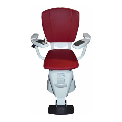
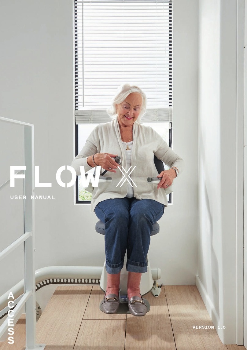
Access Flow2A User manual


2
© 2016 ThyssenKrupp Accessibility BV
All rights reserved.
Specifications and illustrations are subject to change without prior notice. ThyssenKrupp Accessibility BV will not
accept liability for any alteration or typing error.
Subject to the exceptions provided by law, this publication and/or its contents may not be, whether entirely or partly,
reproduced, copied, and/or published in print, by photocopying, on microfilm, electronically or in any other way
without the prior written consent of ThyssenKrupp Accessibility BV.

Table of contents
3
Table of contents
1General __________________________________________________ 5
1.1 Introduction ______________________________________________________________5
1.2 Customer requirements _____________________________________________________6
1.3 Safety aspects ____________________________________________________________7
2The rail___________________________________________________ 8
2.1 Construction______________________________________________________________8
2.2 Rail sections____________________________________________________________ 10
2.3 Rail options ____________________________________________________________ 11
2.4 Charging contacts _______________________________________________________ 12
3The chair ________________________________________________ 13
3.1 Construction____________________________________________________________ 13
3.2 Swivel seat system ______________________________________________________ 15
3.3 Safety mechanisms ______________________________________________________ 17
4The drive unit_____________________________________________ 18
4.1 The drive unit___________________________________________________________ 18
4.1.1 The memory system _______________________________________________________________22
4.1.2 The drive motor system _____________________________________________________________23
4.1.3 The horizontal system ______________________________________________________________29
4.2 User control components__________________________________________________ 31
4.2.1 User control units __________________________________________________________________31
4.2.2 Receiver board operation____________________________________________________________33
4.2.3 Wireless control unit operation _______________________________________________________33
4.2.4 Signals on the control units __________________________________________________________34

Table of contents
4
4.3 Power supply system_____________________________________________________ 34
4.3.1 System assembly__________________________________________________________________34
4.3.2 Switching the stairlift on and off ______________________________________________________35
4.3.3 Charging the batteries ______________________________________________________________35
4.3.4 The rail charging contacts ___________________________________________________________36
4.3.5 The transformer ___________________________________________________________________37
4.3.6 Fuses ___________________________________________________________________________37
4.3.7 Measurement points and led indications ________________________________________________37
4.4 The service board _______________________________________________________ 38
4.4.1 Operation ________________________________________________________________________38
4.4.2 Entering service modes _____________________________________________________________39
4.4.3 Overview of the modes _____________________________________________________________39

General
5
1 General
1.1 Introduction
A stairlift is mostly used for transporting less mobile people in their houses from one house floor to another. This lift
is specifically designed to be used in a home environment by a trained user. Because the lift is primarily used for the
transport of people, safety is an important design consideration. For the user of the lift, ease of operation,
robustness, fearless use, comfortable transport, noise and appearance are important aspects. For service and
installation technicians, the lift must be serviced and installed with minimal tools and be easy to maintain. For the
designer of the lift it is desirable that the system is manageable, modular and easy to adapt to other lift platforms
(reuse of subsystems).
According the Dutch safety standard for stairlift s (NEN EN 8140) a stairlift is an appliance for transporting a person
(either seated or standing) or a person in a wheelchair, between two or more boarding points by means of a guided
carriage moving in an inclined plane.
The Flow2A - Stairlift is a stairlift for seated persons and is a compact stairlift that fits most staircases: whether they
are straight, curved or even spiral stairs. The stairlift can be positioned on either the inside or the outside of the
stairs so that the available width of the stairs remains as usable as possible.
In figure below is shown of the “Flow 2A” stairlift in its resting position at the bottom of the stairs.
Several major parts can be identified:
The transportation drive rail is used as a guidance rail for the motorized chair. This rail is mounted on an existing
staircase through rail mounting fixtures.
The motorized chair is controlled by the user with an armrest control device. Additional RF Control devices are
present at the bottom and top boarding points (Call & Park devices, not shown).
The user sits on the chair equipped with a feet support appliance. The chair and feet rest support can be manually
folded/retracted when not used for transporting a person. This has the function of making the dimensions of the
chair smaller when parked.
The “Flow 2A” is able to keep the chair seat horizontal when the slope of the rail changes. This function is called
levelling.
It is also possible to rotate the chair around its vertical axis (swiveling) in order to manoeuvre through small staircase
environments or to create more space around the legs during transportation or getting on or off the chair. Three
versions are available: No swiveling (Fixed), Manual and motorized swiveling.
The arm rests are collapsible upwards, this allows for the user to easily position himself in the chair. When the arm
rest are in the horizontal position it surrounds the user for safety reasons.
The stairlift is battery operated. If there is an external power failure, the lift can still be operated for a limited time. At
some points along the rail (start location, end location and intermediate parking locations), charging contacts are
present to charge the batteries.

General
6
The Flow 2A - Stairlift
1. Rail Mounting Fixtures
2. User Interface
3. Stairlift Motor System
4. Drive Rail
5. Chair
6. Arm Rest
7. Feet Rest support
A. Swivel axis
B. Level axis
1.2 Customer requirements
This section provides a summary of the possibilities the stairlift offers the customer. See the brochure Product
introduction´ for a detailed overview of the customer options.
Swivel seat system
The stairlift can be equipped with a fixed chair, with a manual swivel seat or with a powered swivel chair. See section
3.2.
Control components
The control unit is placed on the down-facing side of the chair in the armrest. The standard version stairlift is
equipped with two call and park units, but more are possible. Call and park units can be placed at each floor. The
client can also choose for an attendant control. This is for situations in which the user has difficulty operating the
stairlift him or herself.
The control unit is delivered standard with a joystick. In addition the customer can choose for an ergonomically
designed joystick. This can be held and operated with the entire hand.
The standard call and park units and attendant control have a wing-key joystick.

General
7
Rail coating
The rail and chair base are finished with a durable powder coating. The powder coating applied to the rail is available
in a variety of colours. On ordering the stairlift the customer selects the colour most suitable for the interior of the
customer’s home. Customers can select from the following standard colours:
• RAL 9002, grey/white.
• RAL 8019, grey/brown.
• RAL 7046, silk grey.
• RAL 8024, brown/beige.
Although other colours are also possible, the choice of non-standard colour will have consequences for the price and
delivery time.
Stairlift coating
The powder coat applied to the chair is always white and the covers are always a combination of white and brown.
These colours cannot be changed.
Chair upholstery
Two standard materials are available for the chair upholstery, each in its own range of colours:
• Vinyl: red, natural sisal, blue, grey, green and maroon
• Fabric: beige, blue, brown and red.
Both materials are dirt-resistant and fire-retardant.
1.3 Safety aspects
The stairlift is equipped with various techniques to guarantee safe use. In general, all safeguards are duplicated; one
fault may never result in a dangerous situation!
The following safety devices are fitted:
• An over speed device locks the stairlift mechanically if it goes too fast. In that case, the drive motor is also
disconnected electrically (see chapter 4).
• Mechanical end stops at the ends of the rail will trigger the final limit switch to reduce the possibility for the
drive unit to ride off the rail. This should only be possible if there is a technical defect (see chapter 4).
• An obstruction safeguard system ensures that the stairlift stops when the chair is unintentionally rotated
because a person or object obstructs (parts of) the chair.
• Because the stairlift works on batteries, it can still be used when there is a power failure. A safety
mechanism ensures that batteries always have enough charge left for a last trip to a charging contact
located lower down (see chapter 4).
• All chairs are fitted with a safety belt.

The rail
8
2 The rail
The rail is a round steel tube bent to shape to which a tooth rack is welded. Bogie rollers in the drive unit ensure that
the drive unit moves evenly along the round tube. A gear in the drive unit engages in the teeth of the tooth rack. This
provides the drive for the stairlift in the tooth rack on the rail.
2.1 Construction
The rail is made of a round steel tube with a diameter of 80 mm and is bended to follow the curvature of the
staircase. A rack is welded under the rail along which the stairlift moves. The chair is pulled along the rack with a
motorized pinion with teeth that fits in the holes of the rack (Figure 2-1).
Figure 2-1: Rail & Pinion
The motor/pinion combination generates the forces needed to move the chair along the transport rail.
The rail is mounted with several brackets on the staircase steps. It is possible to design the rail and chair system for
operation on the left or right side of the staircase. The shape of the bended transport rail is determined by the
drawing office. This office uses the results of the stairwell measurement. This measurement can be done manually
of with an optical measuring method (Figure 2-2) where markers are placed on critical points on the staircase.
Figure 2-2: Optically measuring the staircase dimensions using photographic markers.
Because the standard production length of the steel tubes is limited, depending on the total length a rail is
constructed from a maximum of 3 sections (2 joints) per storey.
The maximum inclination of the rail is 70º.

The rail
9
Figure 2-3: Minimum distance from the stair threads
In most cases the rail starts vertically on the floor at the bottom. Here the minimum distance from the front of the
stair tread to the front of the rail is 175 mm.
The standard version is equipped with a horizontal section of rail on the top landing. The distance between the front
of the last stair tread and the end of the rail is a minimum of 200 mm.
Ends
The horizontal end of the rail is fitted standard with a cone-shaped rail cover that makes it easier to mount the drive
unit on the rail.
A black flat rail cover (Flow1) is also supplied for situations in which the grey cone-shaped rail cover is not a good
match to the colour of the rail. In this case the cone-shaped rail cover is only used to mount the drive unit, after
which the black flat rail cover can be fitted.
Figure 2-4: Cone-shaped rail cove Figure 2-5: Flat rail cover
Emergency end stop
With a horizontal rail runout, an emergency stop is fitted on the underside of the rack. A counter ensures that the lift
position is retained. To prevent the stairlift moving past a stopping place and running off the rail as a result of
technical problems, a mechanical emergency stop is fitted. This end stop consists of a small strip that is fitted in a
cut-out in the tooth rack.
The emergency stop activates the final limit switch, which stops the drive motor drive and activates the electric
brake.

The rail
10
Figure 2-6: Emergency end stop
2.2 Rail sections
Depending on its shape, the rail can be divided into various sections.
Figure 2-7: Inside and outside curves
Curves in the horizontal plane are called inside curves (2) and outside curves (1). To avoid confusion:
• Looking from the stairs, if you can see the inside of the curve then that is an inside curve.
• If you can see the outside of the curve then that is an outside curve.
In the vertical plane they are called bottom and top curves.
There are also curves in both the horizontal and the vertical plane. Such a curve is called a Spiral.
At the end of the rail there can be a vertical landing or a horizontal landing.
Figure 2-8: Spiral and vertical landing

The rail
11
2.3 Rail options
Longer runout
A longer overrun than the standard-length overrun can be installed at both the top and bottom of the stairs. The
maximum length is limited by the available space.
Maximum rail runout dimensions:
X= needed to install the chair
Left or right rail
The rail can be fitted on either the left or the right side of the stairs. Viewed from the bottom, if the rail is on the right
then it is called a right rail. If the rail is on the left then it is called a left rail.
Parking locations
If there is no room at the start or the end of the rail for parking the stairlift, an extra parking location can be made
along the rail. Any such parking point will need to be located on a straight section or a horizontal bend. The location
of the extra parking location must be such that the parked stairlift does not cause any inconvenience for anyone else
when they use the stairs.
Parking curve:
(1) Normal curve
(2) Opposite curve
X

The rail
12
The parking location must always be on a charging contact so that the batteries can be charged when the stairlift is
not in use.
Extra stopping places
It is possible to define a maximum of 10 stopping places for the stairlift, including the parking locations and the
stopping places at the ends of the rail.
Warning post
Warning posts can be installed in front of horizontal rail sections on the bottom or top landing to draw attention to the
risk of stumbling over the rail.
Figure 2-9: Warning posts
2.4 Charging contacts
The charging contacts are part of the power supply system.
Figure 2-10: Standard charging contact Figure 2-11: Mobile charging contact
The positions of the charging contacts must match the positions of the parking and stopping places. Mount the
charging contacts on the rail using the supports so that the brush contacts on the drive unit contact the centre of the
charging contacts.
Mobile charging contacts are also available, which can be placed anywhere along the rail after installation.

The chair
13
3 The chair
3.1 Construction
Frame
The chair consists of a frame on which a seat and a back cushion are fitted. The armrests can be folded up so that it
is easier to get into and out of the chair. The chair can be fitted with straight or curved armrests, these are
interchangeable by pair. On a stairlift with a fixed chair or manual swivel seat, straight armrests are installed
standard. On a stairlift with a powered swivel seat system, the chair is fitted with curved armrests. This keeps the
space required for turning as small as possible.
Figure 3-1: Folded Chair
Controls
In compliance with the CE approval, the armrest on the down-facing side of the stairs is fitted with a control unit. On
a stairlift with a left rail this is thus the right armrest and on a stairlift with a right rail this is the left armrest (also see
Section 2.3).
Chair height adjustment
The height of the chair can be adjusted to one of 4 positions (Tab 04 - Installation manual).
Figure 3-2: Chair height adjustment

The chair
14
Footrest
Figure 3-3: Short footrest
The stairlift can be equipped with two types of footrests:
• The standard type (default);
• A short version, optional for situations in which the passage of a chair with standard footrest is hindered,
such as in the case of a narrow stairwell.
The footrest is attached to the chair frame and can be folded up.
If the seat position is raised, the footrest must be lowered so that the distance between the footrest and the stair
remain the same, but the distance between footrest and seat is increased. In this way the chair can be adjusted to
the height of the user (Tab 04 - Installation manual).
Chair folding mechanism
The seat can be folded by lifting the front of the seat until the seat is vertical. The movement is dampened by a gas
spring.
The footrest can be folded by lifting the handle at the front until the support is vertical
Unfolding can be done by moving the footrest and the seat back to the horizontal position.

The chair
15
3.2 Swivel seat system
The stairlift can be fitted with a fixed chair, a manual swivel seat or a powered swivel seat.
Fixed chair
With a fixed chair the chair is attached to the drive unit. To make it easier to step on and off, it is convenient if the
seat is turned at the bottom and the top. In that case a manual swivel seat can be fitted. If the user also wants to
turn to a comfortable position while moving, or a small stairwell makes it necessary, a powered swivel seat must be
fitted.
Figure 3-4: Fixed chair Figure 3-5: Manual swivel seat system
Manual swivel seat
With the manual swivel seat mechanism the chair frame is connected to the drive unit via an arm. The chair frame
can pivot 70⁰around the arm by lifting one of levers on either side of the chair frame. At the end positions the chair
can be locked in place by lowering the lever again.
The direction of rotation is dependent on the position at which the chair must rotate. This cannot be changed.
The manually operated swivel seat is fitted at the top as standard to make stepping on and off easier. In this case at
the bottom the chair may only turn the “wrong” way (towards the stairs).
If the swivel has to be fitted at the bottom, a runout must be positioned at the top to avoid the need to run the chair
over the stairwell at the top. At the bottom the rail may not be steeper than 60⁰because otherwise the chair frame
will strike the rail while turning.
Powered swivel seat
When a stairlift is fitted with a powered swivel seat mechanism, an electric motor (Figure 3-6) drives the vertical
support of the chair mounting through a planetary gear system.
Figure 3-6: Swivel motor

The chair
16
The chair with a powered swivel seat can turn both 110⁰clockwise and 110⁰counter-clockwise, depending on the
rail and stairs. The electric motor is controlled by the electronics and the rotation is fully programmable in steps of
5⁰.
While moving, the chair is turned to the best position so that it can move up and down a narrow stairwell. At the
beginning and end of the travel the chair turns automatically to the position that provides the most room to make
stepping on and off easier.
Figure 3-7: Powered swivel seat
The desired rotation angle at any point along the rail is given by the recorded position of the carriage and the rail
data table which is programmed in the control boards memory. The required swivel angles are different for every
installed stairlift. The rotation angle is determined by an encoder. Additionally an opto coupler is used for detection
of the zero angle (reset) position (Figure 3-8). The zero position is detected when the flag has just left the opto
coupler. The motor is controlled in a feedback loop using the encoder of the swivel motor to achieve the desired
angle.
Figure 3-8: Swivel zero opto coupler Swivel squeeze opto coupler
Opto coupler
fla
g

The chair
17
3.3 Safety mechanisms
Obstruction safeguard
The pivot under the chair is kept in a specified position during movement by springs (also with a fixed chair). This
position is monitored by an opto coupler. If the chair is in the right position, the control is released.
The maximum allowed swivel angles are not protected by limit switches or mechanical stops. It is expected that
when the chair rotates too much the footrest will hit an obstruction and then will be triggered by the anti-squeeze
mechanism which also uses an opto coupler (Figure 3-8).
At the moment that the chair runs into an obstruction, the chair is pushed out of position against the spring
pressure. The opto coupler detects that the chair has turned and signals this to the control.
The control will the execute an emergency stop sequence by placing the motor in active brake mode followed by an
action to activate the friction brake.
The drive is stopped immediately. The user can no longer move any further forwards, but can move backwards for
max 10cm
The user can continue moving forwards after removing the obstacle.
Figure 3-9: Swivel motor control principle

The drive unit
18
4 The drive unit
4.1 The drive unit
The drive system and the system for keeping the chair base horizontal (level) is located in the drive unit.
The drive unit consist of a number of boards, namely:
• Control board
• Chair level sensor board
• Safety level sensor board
• Hub board
• Receiver board
• Service board
And the drive unit also includes a drive motor, a horizontal motor and (if present) a swivel seat motor.

The drive unit
19
Adapter
Battery
Charger
Supply
Audio amplifier &
Speaker
Accelerometer
(inlcino) Gyroscope
Non-volatile
Memory – MicroSD
Card interface
Non-volatile
Memory-
EEPROM
Micorcontroller
STM32 family
Interfaces
(RF/Bus
Communcation/
Switches/UI/
Service tool)
Safety control
Brake Drive motor control Drive hall sensor
interface Level motor control Level hall sensor
interface
Swivel motor
control
Swivel hall sensor
interface
Hubboard
Service Board
RF Tranceiver
On/off switch
OSD Opto switch
USB interface
Safety level sensor
board
Swivel
Optiocouplers
(auto: 2x
Man: 1x)
Chair level sensor
board
Bootloader
(not in
manufacturing
Drive-in module
Anti squeeze opto
Switches (6x)
[optional]
BLDC Drive
motor
BLDC Level
motor
PM Swivel
motor
APOLLO CONTROL BOARD
Figure 4-1: Schematic diagram

The drive unit
20
The control board
The stairlift is a processor controlled system. The drive unit contains a control board that is accessible when the
drive cover is removed.
Control board (top view)
The control board has the following functionalities:
• Supply and charge
• Drive motor control
• Level motor control
• Swivel motor control
• Brake control
• Gyroscope & accelerometer
• Microcontroller
• Audio amplifier / Speaker
• Memory (storage)
• Interfaces
• Supporting boards
Chair sensor board
The chair sensor board is mounted in the back of the pedestal of the drive unit. It is connected with the system with
a cable to the hub board.
The chair sensor is part of the levelling system and is providing the system with the information about the angle of
the chair.
Figure 4-2: Chair sensor board
Other manuals for Flow2A
1
Table of contents
Other Access Mobility Aid manuals