AccuMac AM8060 User manual

AM8060 Precision Thermometer
User’s Guide

AM8060 Precision Thermometer
User’s Guide
1/43
Table of Contents
Important Notice ---- Warning........................................................................................... 2
1 Introduction................................................................................................................. 3
1.1 Main Application ................................................................................................ 3
1.2 Main Features...................................................................................................... 3
2 Specifications .............................................................................................................. 5
2.1 Specifications ...................................................................................................... 5
2.2 Probe Types ........................................................................................................ 5
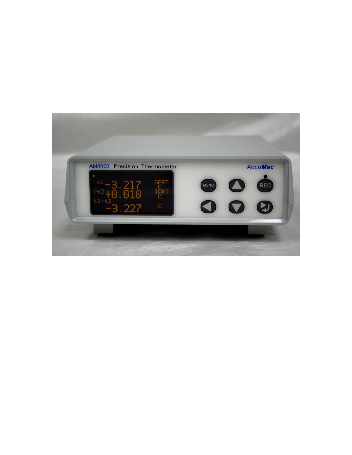
3 User Interface ............................................................................................................. 6
4 General Operations .................................................................................................... 7
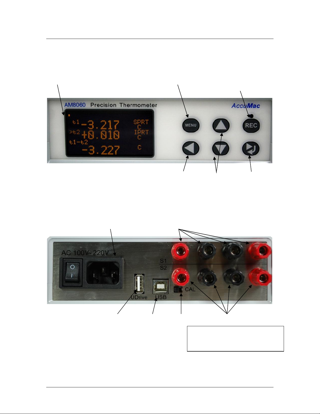
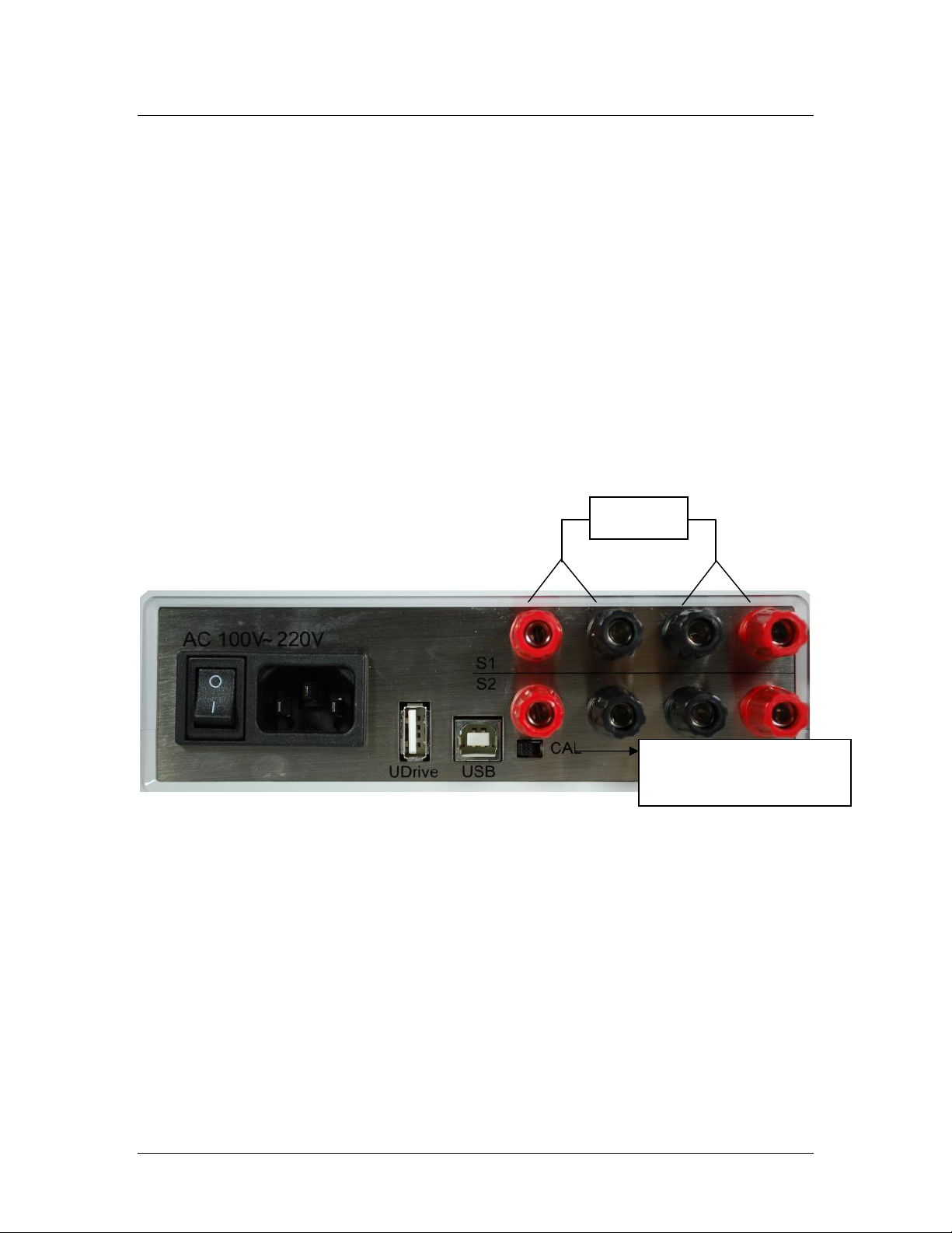
4.1 Connecting the probes......................................................................................... 7
4.2 Instrument connection with AC power ............................................................... 7
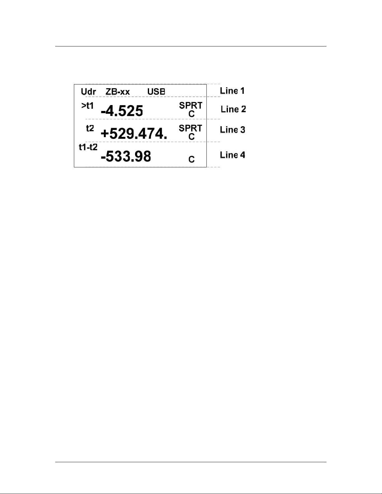
4.3 Instrument front panel display and touchpad. ..................................................... 7
4.4 Selecting Units .................................................................................................... 9
4.5 Selecting Sensors/Probes and Adjusting Parameters .......................................... 9
5 Instrument Calibration And Accuracy Adjustments ................................................. 17
5.1 100 Ω calibration .............................................................................................. 18
5.2 25 Ω calibration ................................................................................................ 20
5.3 Reset the measurement/calibration switch after calibration ........................... 23
6 Wireless Data Acquisition......................................................................................... 24
7 Using a Flash Drive
(
U disk
)
for Data Acquisition............................................... 30
8 Using the USB Interface for Data Acquisition ......................................................... 35
9 Appendix: Installation of USB Driver....................................................................... 39
Please read the “
Important Notice”
information on the next page before
turning on the instrument!

AM8060 Precision Thermometer
User’s Guide
2/43
Important Notice ---- Warning
Check the position of the “Measurement/Calibration
Switch” on the rear panel before turning on the device.
Please refer to Figure 2. The switch must be at the
measurement (left) position. Loss of calibration data will
occur if the switch is at the calibration (CAL) position
when the instrument is used in measurement application.
The instrument is calibrated before shipment. Only
qualified calibration agencies should use the switch when
the instrument is under calibration. Please refer to 5.
Instrument Calibration And Accuracy Adjustments

AM8060 Precision Thermometer
User’s Guide
3/43
1 Introduction
The AM8060 precision thermometer is a dual-channel temperature
readout. It can be used as either a temperature measurement device
or a temperature reference standard. It is capable of working
together with various types of platinum resistance thermometers
(PRTs) and can measure temperatures from two probes
simultaneously. The measured temperature is calculated by the
embedded microcontroller by following ITS-90 standard. The
device can also be equipped with a wireless data acquisition
function, a USB data acquisition and a flash drive interface. With
these flexible peripherals, temperature data can be easily captured
and saved in real time.
1.1 Main Application
Temperature measurement with standard platinum
resistance thermometers (SPRTs), secondary platinum
resistance thermometers (Secondary PRTs) and precision
industrial platinum resistance thermometers (IPRTs).
Either temperature reference standard or temperature
measurement.
Temperature reference for dry-wells or temperature baths.
Wireless/wire/flash real time temperature measurement/data
capturing.
1.2 Main Features
High accuracy: 0.006 ºC at 0 ºC
High resolution,0.001 ºC
Concurrent two PRTs measurement and data capturing.
Display of two PRTs temperature in Celsius ºC,ºF,
resistance Ω and temperature difference.
2.7” OLED display.
Touchpad for function control.

AM8060 Precision Thermometer
User’s Guide
4/43
Flexible probe/sensor parameter adjustments and settings.
USB interface for transmitting and saving real time
temperature data.
Wireless real time temperature data capturing with optional
external wireless module.
Real time temperature data capturing and saving to flash
drive.

AM8060 Precision Thermometer
User’s Guide
5/43
2 Specifications
2.1 Specifications
Temperature range:-200 ºC ~ 850 ºC
Resolution:0.001 ºC
Accuracy:
25Ω standard platinum
temperature probe
100Ω standard or industrial
platinum temperature probe
±0.01 ºC @ -196 ºC
±0.010 ºC @ -200 ºC
±0.008 ºC @ 0 ºC
±0.008 ºC @ 0 ºC
±0.009 ºC @ 232 ºC
±0.009 ºC @ 232 ºC
±0.015 ºC @ 420 ºC
±0.015 ºC @ 420 ºC
±0.025 ºC @ 660 ºC
±0.020 ºC @ 660 ºC
±0.025 ºC @ 850 ºC
Short term stability:
o±0.001 ºC(with 100Ω platinum probe)
o±0.003 ºC(with 25Ω platinum probe)
Working environment:15ºC ~ 35 ºC
Power supply:AC 100V ~ 220V
Power consumption:< 15 W
Dimensions :180 mm x 65 mm x 200 mm
Weight :0.7 lbs (300 g)
2.2 Probe Types
SPRT or PRT with temperature coefficient α=0.003925
(WGa≥1.11807).
IPRT with temperature coefficient α=0.00385.

AM8060 Precision Thermometer
User’s Guide
6/43
3 User Interface
Front Panel:
Display Main Menu U Drive recording
Start/Stop button
Left key Value Adj Right/Return Key
Figure 1: Front Panel.
Rear Panel:
AC Power Inlet/Switch Probe 1(S1) terminals
U Drive Interface USB Measurement Probe 2(S2) terminals
/Calibration
Switch
Figure 2:Rear Panel
Warning: unless calibration is
needed,
do NOT put the switch on ‘Cal’
position.

AM8060 Precision Thermometer
User’s Guide
7/43
4 General Operations
The AM8060 precision thermometer is a dual-channel temperature
readout. It can measure temperature of two probes concurrently. It
can also be used with just one probe for single channel temperature
measurement.
4.1 Connecting the probes
The AM8060 can work with one or two probes for temperature
measurement. Figure 3 shows the rear panel of the AM8060.
Probe 1 can be connected to terminals marked with S1, and
Probe 2 to S2.
Figure 3: Rear Panel and Probe Terminals.
4.2 Instrument connection with AC power
AM8060 operation requires power of AC100V~220V.
4.3 Instrument front panel display and touchpad.
After the power is turned on and the probes are connected, the
device should show initialization information, including the
instrument interface status, measured temperatures of the
Set to CAL when doing
Calibration.
Probes

AM8060 Precision Thermometer
User’s Guide
8/43
probe/probes and temperature difference. This information is
shown in 4 lines, as seen below:
Line 1 is the instrument interface status, including USB flash
drive, wireless communication status and USB to computer
interface status. If the “Udr”is shown in Line 1, a USB flash
drive is connected to the USB host interface; if “ZB-xx (where
“xx” are numbers) displays on Line 1 as shown above, it means
the Zigbee wireless data capturing is working; if the display
shows“USB”on Line 1, then AM8060 is connected via its
USB client interface.
Line 2, which is indicated with ‘t1’, shows the measured
temperature of Probe 1 (S1). The“SPRT” at the end of the
Line 2 tells the type of probe of Probe 1 (S1). The AM8060
supports two types of probes. “SPRT” indicates a 25Ω or 100 Ω
standard platinum resistance thermometers. “IPRT” indicates a
100Ω industrial platinum resistance thermometer. The “C”
shown at the end of Line 2 indicates that the temperature is in
Celsius.
Line 3, which is indicated with ‘t2’, shows the measured
temperature of Probe 2 (S2).

AM8060 Precision Thermometer
User’s Guide
9/43
A “>” will toggle in front of “t1” or ”t2” to indicate which probe
is being measured. Each toggling instance is one measurement.
Line 4, which is indicated with “t1-t2”, shows the temperature
difference of the two probes.
4.4 Selecting Units
Users can select to display ºC, ºF or Ω by scrolling touch keys up
or down ( or )
4.5 Selecting Sensors/Probes and Adjusting Parameters
4.5.1 Probe Types
AM8060 can work with different types of PRTs. Users can
choose probe types and input the parameters of the probes.
The menu key
MENU
and return/right shift key can be used
for probe selection and parameter adjustment.
The probes compatible with AM8060 are:
25 Ω or 100 Ω SPRTs, or
25 Ω or 100 Ω Secondary PRTs, or
100 Ω IPRTs.
The temperature coefficient of these probes can either be
0.00385 Ω/Ω/°C or 0.003925 Ω/Ω/°C.
The probe types working with AM8060 are classified and
displayed as IPRT and SPRT:

AM8060 Precision Thermometer
User’s Guide
10/43
If the probe is an industrial or precision platinum
resistance thermometer probe with a temperature
coefficient of 0.00385 Ω/Ω/°C, AM8060 will categorize
the probe as “IPRT”. AM8060 calculates temperature
according to CVD (IEC751) equation.
If the probe is a precision platinum resistance
thermometer probe or secondary PRT with temperature
coefficient of 0.003925 Ω/Ω/°C (WGa>=1.11807),
AM8060 will categorize the probe as “SPRT”. AM8060
calculates temperature according to ITS-90 standard
platinum resistance thermometer equations.
If the probe is a standard platinum resistance thermometer,
the probe will be displayed as “SPRT”. AM8060
calculates temperature according to ITS-90 standard
platinum resistance thermometer equations.
4.5.2 Selecting Sensors/Probe and Parameters Input
4.5.2.1 To select the type of sensor, press
MENU
key and then
hold key. After 3 seconds, AM8060 will display the
parameter adjustment main menu:
There are four options for parameter adjustments:

AM8060 Precision Thermometer
User’s Guide
11/43
Sensor 1 Setting. This is for Sensor 1 (S1) parameter
adjustment. Users can select the Sensor 1 type and do
parameter adjustment.
Sensor 2 Setting. This is for Sensor 2 (S2) parameter
adjustment. Users can select the Sensor 2 type and do
parameter adjustment.
U-Drive Setting. Users can select this to change settings
for saving data to an external drive.
Wireless Setting. Users can select this to change the
settings for wireless communication.
Although only “Sensor 1 Setting” is illustrated below, the
procedure of Sensor 1 and Sensor 2 adjustments are
identical.

AM8060 Precision Thermometer
User’s Guide
12/43
4.5.2.2 Press or key to move the selection line with the
“>” symbol to “Sensor 1 Setting”. Press key to enter
the Sensor 1 setting adjustment program as shown
below. The probe type can either be “IPRT” or “SPRT”.
Users can select either one by moving the “>” to the
sensor type, and then press key. Users can exit this
selection by pressing
MENU
key. The figure below shows
that SPRT is selected.
4.5.2.3 Press key to go to the parameter adjustment menu:

AM8060 Precision Thermometer
User’s Guide
13/43
4.5.2.4 If the sensor type is SPRT, the adjustable
parameters are Rtp, a, b, c, a4 and b4. The details of
these parameter definitions can be found from the ITS-
90.
As an example, calibration agencies provide following
parameters after SPRT is calibrated:
Rtp: probe’s resistance at triple point of water.
a4 and b4:low temperature range parameters.
a, b and c:high temperature range parameters (b and c can
be “0” for some instances. (Please refer to ITS-90 for more
information.)
If the sensor type is IPRT, the adjustable parameters are R0,
A, B and C:
The details of the parameter definitions can be found from
the industrial platinum resistance thermometer calibration
procedure.
As an example, calibration agencies provide following
parameters after IPRT is calibrated:
R0: the probe’s resistance at 0°C.
A and B: the temperature coefficients at temperature range
above 0°C.

AM8060 Precision Thermometer
User’s Guide
14/43
C: the temperature coefficient at the temperature range
below 0°C.
4.5.2.5 The
MENU
, , , and keys can be used
together to adjust these parameters. The parameters can
also be saved into the instrument. The following is the
procedure of adjusting and saving the parameters of Rtp
and a4 for an SPRT type probe. The other parameter
adjustments follow the same process.
4.5.2.6 To adjust Rtp (continuing from step 4.5.2.4) press
or key to move the cursor to “>SET Rtp”, and
then press key to go into the Rtp adjustment
program.
The instrument will display the current Rtp value. The digit
underlined with the blinking bar indicates the adjustable
position. Users can use and keys to move this
position and use and keys to adjust the value.
4.5.2.7 After the Rtp is adjusted, press
MENU
key, the display
will remind user to save the adjusted value by flashing
the adjusted Rtp on screen. Press key to save the

AM8060 Precision Thermometer
User’s Guide
15/43
value or press
MENU
key to exit the program without
saving and go back to the parameter adjustment menu.
4.5.2.8 The following is a4 adjustment procedure
(Continuing from step 4.5.2.4). Pressing and keys
to move the cursor to “>SET a4”, and then press key
to go into the a4 adjustment program, as seen below:
The second line (a4 = -4.129934e-05) displays the current
a4 value, while the next two lines show the adjustment
selections. The a4 adjustment is different from Rtp, as the
value of a4 can be “0”. If a4 is “0”, the user can move the
cursor by using and keys to “SET A4=0” line and
press the key to confirm the selection. If a4 is a value
other than “0”, the user can move the cursor to “ADJUST
a4” line and then press key to go into the a4
adjustment program.

AM8060 Precision Thermometer
User’s Guide
16/43
4.5.2.9 The current a4 value will be displayed. To adjust
this value, press or key to move the cursor to the
position where the value will be adjusted and then adjust
it with or key.
4.5.2.10 After adjustment, users can choose to save or quit
by pressing the
MENU
key. The a4 line will be flashing to
remind the user that a change has been made. To save
the changes, press key; otherwise, press
MENU
key and
the program will go back to the previous screen.
4.5.2.11 Other parameter adjustments are similar to the
above Rtp and a4 adjustment.
4.5.2.12 After all of the desired adjustments are made, users
can go back to the main menu by pressing
MENU
key
multiple times until the AM8060 goes back to the main
screen.

AM8060 Precision Thermometer
User’s Guide
17/43
5 Instrument Calibration And Accuracy
Adjustments
AM8060 is designed for temperature measurement by measuring
the probe resistance and converting it into a temperature.
Consequently, the resistance measurement is very critical, and the
instrument must be calibrated correctly. Every AM8060 is
calibrated before shipment.
AM8060 needs regular calibration performed by qualified
professionals. One year calibration interval is recommended.
Users can calibrate AM8060 using standard resistors with
calibrated values.
Warning: It is required to set correct R0 (Rtpw) values in Sensor 1
(S1) before calibrations. To calibrate AM8060 in the range from
10 Ω to 50 Ω, R0 (Rtpw) needs to be set to 25 Ω. To calibrate
AM8060 in the range from 50 Ω to 375 Ω R0 (Rtpw) needs to be
set to 100 Ω.
In case of AM8060 out of tolerance, its accuracy can be adjusted.
Only qualified agencies, labs or institutes (who must be equipped
with calibrated 25 Ω and 100 Ω standard resistors) should adjust
the accuracy of AM8060.
The calibration should be done in an environment with room
temperature of 22±2°C.
Instrument calibration procedure: (No special sequence
for 100 Ωand 25 Ωcalibration)

AM8060 Precision Thermometer
User’s Guide
18/43
5.1 100 Ω calibration
5.1.1 Turn off the power, put the measurement/calibration switch
to the “CAL”side (right side). Please see Figure 3 for details.
5.1.2 After turning on the power,AM8060 shows the calibration
main menu. It can be seen that there are two calibrations
required: 100 Ohm CALIBRATION and 25 Ohm
CALIBRATION.
The following is an illustration of 100 Ohm CALIBRATION.
* CALIBRATION MENU *
> 100 Ohm CALIBRATION
25 Ohm CALIBRATION
Enter = Yes
-------------------------------------------
5.1.3 Use or key on the keypad to select the calibration. A
“>” sign will be displayed in front of the selected line. For
example, the above figure shows that 100 Ohm
CALIBRATION has been selected. Pressing the key will
start the calibration program, and the following display will
appear:

AM8060 Precision Thermometer
User’s Guide
19/43
* 100 Ohm CALIBRATION
Connect a 100 Ohm
Standard Resistor
and Press Enter
Menu= Exit Enter = Yes
-------------------------------------------
5.1.4 The instrument will show the phrase “Connect a 100 Ohm
Standard Resistor and Press Enter” to indicate that a 100Ω
must be connected to sensor1 (S1) terminals as Figure3.
Users can exit the calibration by pressing
MENU
key to go back
to the main menu (*CALIBRATION MENU*).
5.1.5 After the probe is correctly connected, press key to start
the calibration. The instrument will display “Waiting…”
while the resistance is calibrated. When the process is
finished, the screen will display the result as seen below:
* 100 Ohm CALIBRATION
100.0238
Rt = 111.0000 OHM
Menu= Exit <^v>=Adj
100R Rs = OHM
5.1.6 To calibrate the instrument, users must adjust the value
(100.0238 as shown above) to match the standard resistor’s
resistance. For example, if the resistance of the standard
resistor is 100.0038 ohm, users can move the underline
cursor to the desired position using and keys, and
Other manuals for AM8060
1
Table of contents
Other AccuMac Thermometer manuals

AccuMac
AccuMac AM1850 User manual

AccuMac
AccuMac AM1640 User manual

AccuMac
AccuMac AM8010 User manual

AccuMac
AccuMac AM1760 User manual

AccuMac
AccuMac AM1751 User manual

AccuMac
AccuMac AM1710 User manual

AccuMac
AccuMac AM8040 User manual

AccuMac
AccuMac AM1750 User manual

AccuMac
AccuMac AM1660 User manual

AccuMac
AccuMac AM1950 User manual