Eurotron IRtec Rayomatic 20 User manual
EUROTRON Instruments S.p.A.
Viale F.lli Casiraghi 409/413
20099 Sesto S.Giovanni (MI) - Ital
Tel. +39-02 248820.1 Fax +39-02 2440286
eurotron
IRtec Rayomatic 20/40
Process Infrared Thermometers
Instruction Manual MM850341 ed.01a

________________________________________________ _______________________________________________
Instruction Manual MM850341 ed.01a
___________________________________________2____________________________________________
INTRODUCTORY NOTE
A
TTENTION
: T
HIS MA NUAL IS VALID F OR
IR
TEC
R
AYOMATIC
20/40
WITH SERIAL NUMBER HIGHER THAN
0038294.
This publication contains operating instructions, as well as a description of the principles of operation,
of
IRtec Rayomatic 20/40
IR thermometers.
This information covers all models of the instrument, including the basic equipment and its options and
accessories. This manual is a complete “USER UIDE”, providing step-by-step instructions to operate
the instrument in each of its designed functions.
Eurotron
has used the best care and efforts in preparing this book and believes the information in this
publication are accurate. The
Eurotron
products are subjected to continuous improvement, in order to
pursue the technological leadership; these improvements could require changes to the information of
this book.
Eurotron
reserves the right to change such information without notice.
No part of this document may be stored in a retrieval system, or transmitted in any form, electronic or
mechanical, without prior written permission of
Eurotron Instruments.
IRtec
IR thermometers u ses sophisticated analogic and digital technologies. A ny m aintenance
operation must be carried out by qualified personnel
ONLY
. We recommend to contact our technicians
for any support requirements.
IRtec
is fully tested in conformity with the directive n°89/336/CEE Electromagnetic Compatibility.
Eurotron
shall not be liable in any event, technical and publishing error or omissions, for any
incidental and consequential damages, in connection with, or arising out of the use of this book.
IRtec is a registered trademark of Eurotron Instruments S.p. .
ll right reserved
Copyright © 2000, 01
EUROTRON Instruments S.p.A.
Viale Fratelli Casiraghi 409/413
20099 Sesto San Giovanni (MI) – Italy
Tel.: +39-02 248820.1 – Fax: +39-02 2440286
e-mail: info@eurotron.com
http://www.eurotron.com
________________________________________________ _______________________________________________
Instruction Manual MM850341 ed.01a
___________________________________________3____________________________________________
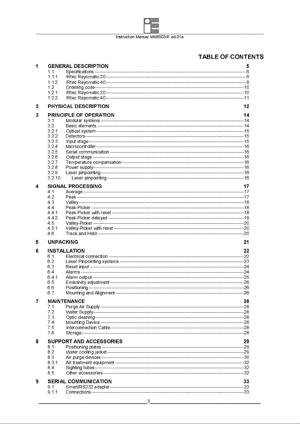
TABLE OF CONTENTS
1
GENERAL DESCRIPTION 5
1.1
Specifications ------------------------------------------------------------------------------------------------ 6
1.1.1
IRtec Rayo atic 20----------------------------------------------------------------------------------------- 6
1.1.2
IRtec Rayo atic 40----------------------------------------------------------------------------------------- 8
1.2
Ordering code-----------------------------------------------------------------------------------------------10
1.2.1
IRtec Rayo atic 20----------------------------------------------------------------------------------------10
1.2.2
IRtec Rayo atic 40----------------------------------------------------------------------------------------11
2
PHYSICAL DESCRIPTION 12
3
PRINCIPLE OF OPERATION 14
3.1
Modular syste s-------------------------------------------------------------------------------------------14
3.2
Basic ele ents ---------------------------------------------------------------------------------------------14
3.2.1
Optical syste ----------------------------------------------------------------------------------------------15
3.2.2
Detectors-----------------------------------------------------------------------------------------------------15
3.2.3
Input stage---------------------------------------------------------------------------------------------------15
3.2.4
Microcontroller----------------------------------------------------------------------------------------------16
3.2.5
Serial co unica tion -------------------------------------------------------------------------------------16
3.2.6
Output stage ------------------------------------------------------------------------------------------------16
3.2.7
Te perature co pensation------------------------------------------------------------------------------16
3.2.8
Power supply------------------------------------------------------------------------------------------------16
3.2.9
Laser pinpointing-------------------------------------------------------------------------------------------16
3.2.10
Laser pinpointing---------------------------------------------------------------------------------------16
4
SIGNAL PROCESSING 17
4.1
Average ------------------------------------------------------------------------------------------------------17
4.2
Peak ----------------------------------------------------------------------------------------------------------17
4.3
Valley---------------------------------------------------------------------------------------------------------18
4.4
Peak-Picker -------------------------------------------------------------------------------------------------18
4.4.1
Peak-Picker with reset ------------------------------------------------------------------------------------18
4.4.2
Peak-Picker delayed --------------------------------------------------------------------------------------19
4.5
Valley-Picker ------------------------------------------------------------------------------------------------20
4.5.1
Valley-Picker with reset-----------------------------------------------------------------------------------20
4.6
Track and Hold ---------------------------------------------------------------------------------------------20
5
UNPACKING 21
6
INSTALLATION 22
6.1
Electrical connection --------------------------------------------------------------------------------------22
6.2
Laser Pinpointing syste s -------------------------------------------------------------------------------23
6.3
Reset input --------------------------------------------------------------------------------------------------24
6.4
Alar s--------------------------------------------------------------------------------------------------------24
6.4.1
Alar output -------------------------------------------------------------------------------------------------25
6.5
E issivity adjust ent -------------------------------------------------------------------------------------26
6.6
Positioning---------------------------------------------------------------------------------------------------26
6.7
Mounting and Align ent----------------------------------------------------------------------------------26
7
MAINTENANCE 28
7.1
Purge Air Supply -------------------------------------------------------------------------------------------28
7.2
Water Supply------------------------------------------------------------------------------------------------28
7.3
Optic cleaning-----------------------------------------------------------------------------------------------28
7.4
Mounting Device -------------------------------------------------------------------------------------------28
7.5
Interconnection Cable-------------------------------------------------------------------------------------28
7.6
Storage-------------------------------------------------------------------------------------------------------28
8
SUPPORT AND ACCESSORIES 29
8.1
Positioning plates ------------------------------------------------------------------------------------------29
8.2
Water cooling jacket---------------------------------------------------------------------------------------29
8.3
Air purge devices-------------------------------------------------------------------------------------------30
8.3.1
Air treat ent equip ent----------------------------------------------------------------------------------32
8.4
Sighting tubes-----------------------------------------------------------------------------------------------32
8.5
Other accessories------------------------------------------------------------------------------------------32
9
SERIAL COMMUNICATION 33
9.1
S art/RS232 adapter-------------------------------------------------------------------------------------33
9.1.1
Connections-------------------------------------------------------------------------------------------------33

________________________________________________ _______________________________________________
Instruction Manual MM850341 ed.01a
___________________________________________4____________________________________________
10
CONFIGURATION SOFTWARE 35
10.1
Load configuration -----------------------------------------------------------------------------------------35
10.2
Change the configuration---------------------------------------------------------------------------------35
10.3
Save configuration-----------------------------------------------------------------------------------------37
10.4
Monitor -------------------------------------------------------------------------------------------------------37
11
LOGMAN GRAPHIC SOFTWARE 38
11.1
Start acquisition --------------------------------------------------------------------------------------------38
11.2
Configuration------------------------------------------------------------------------------------------------38
12
LOGMAN LOGGING DATA MANAGER 41
12.1
Progra Archi tectu re--------------------------------------------------------------------------------------41
12.1.1
Toolbars--------------------------------------------------------------------------------------------------42
13
CERTIFICATES 45
13.1
Warranty Ter s --------------------------------------------------------------------------------------------45
13.2
Letter of Confor it y----------------------------------------------------------------------------------------45
APPENDI 46
A1
EMC Confor ity------------------------------------------------------------------------------------------------47
A2
How to deter ine an object e issiv it y --------------------------------------------------------------------49
A2.1
Typical E issi vi ty Values---------------------------------------------------------------------------------49
A2.2
Metals - Typical E iss iv ity Values ---------------------------------------------------------------------50
A2.3
Non-Metals - Typica l E iss iv it y Values --------------------------------------------------------------52
________________________________________________ _______________________________________________
Instruction Manual MM850341 ed.01a
___________________________________________5____________________________________________
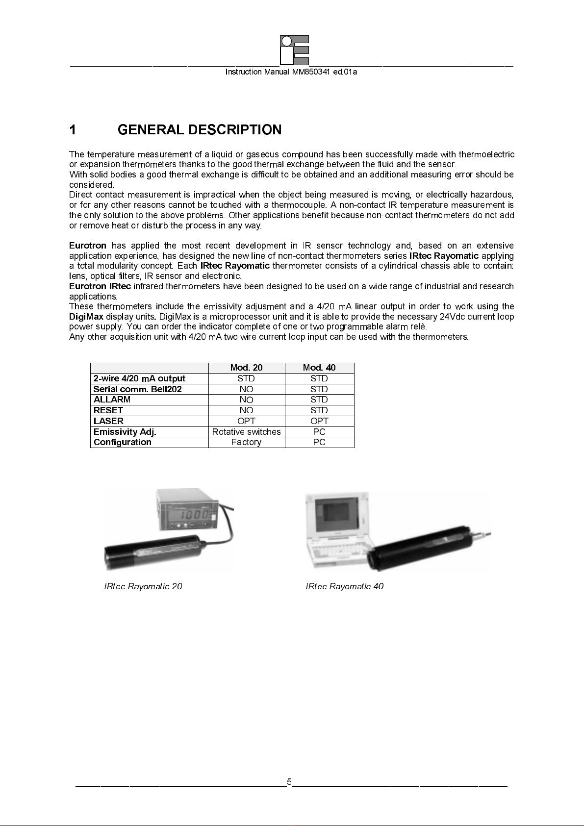
1 GENERAL DESCRIPTION
The te perature easure ent of a liquid or gaseous co pound has been successfully ade with ther oelectric
or expansion ther o eters thanks to the good ther al exchange between the fluid and the sensor.
Wi t h soli d bodies a good ther a l exchange is di ff icu lt to be obta ined and an additio nal easur ing error should be
considered.
Direct contact easure ent is i practical when the object being easured is oving, or electrically hazardous,
or for any other reasons cannot be touched with a ther ocouple. A non-contact IR te perature easure ent is
the only solution to the above proble s. Other applications benefit because non-contact ther o eters do not add
or re ove heat or disturb the process in any way.
Eurotron
has applied the ost recent develop ent in IR sensor technology and, based on an extensive
applica ti on experience, has designed the new line of non- con tac t ther o eters ser ies
IRtec Rayomatic
applying
a total odularity concept. Each
IRtec Rayomatic
ther o eter consists of a cylind r ica l chass is able to co nta in :
lens, optical filters, IR sensor and electronic.
Eurotron
IRtec
infra red ther o eters have been designed to be used on a wide range of indust r ial and research
applications.
These ther o eters include the e issivity adjus ent and a 4/20 A linear output in order to work using the
DigiMax
display units
.
DigiMax is a icrop rocessor un it and i t is able to prov ide the necessary 24Vdc current loop
power supply. You can order the indi cat or co plete of one or two prog ra a ble ala r relè.
Any other acquisi t ion unit with 4/20 A two wire current loo p i nput can be used with the ther o eters.
Mod. 20 Mod. 40
2 wire 4/20 mA output
STD STD
Serial comm. Bell202
NO STD
ALLARM
NO STD
RESET
NO STD
LASER
OPT OPT
Emissivity Adj.
Rotative switches
PC
Configuration
Factory PC
IRtec Rayomatic 20 IRtec Rayomatic 40
________________________________________________ _______________________________________________
Instruction Manual MM850341 ed.01a
___________________________________________6____________________________________________
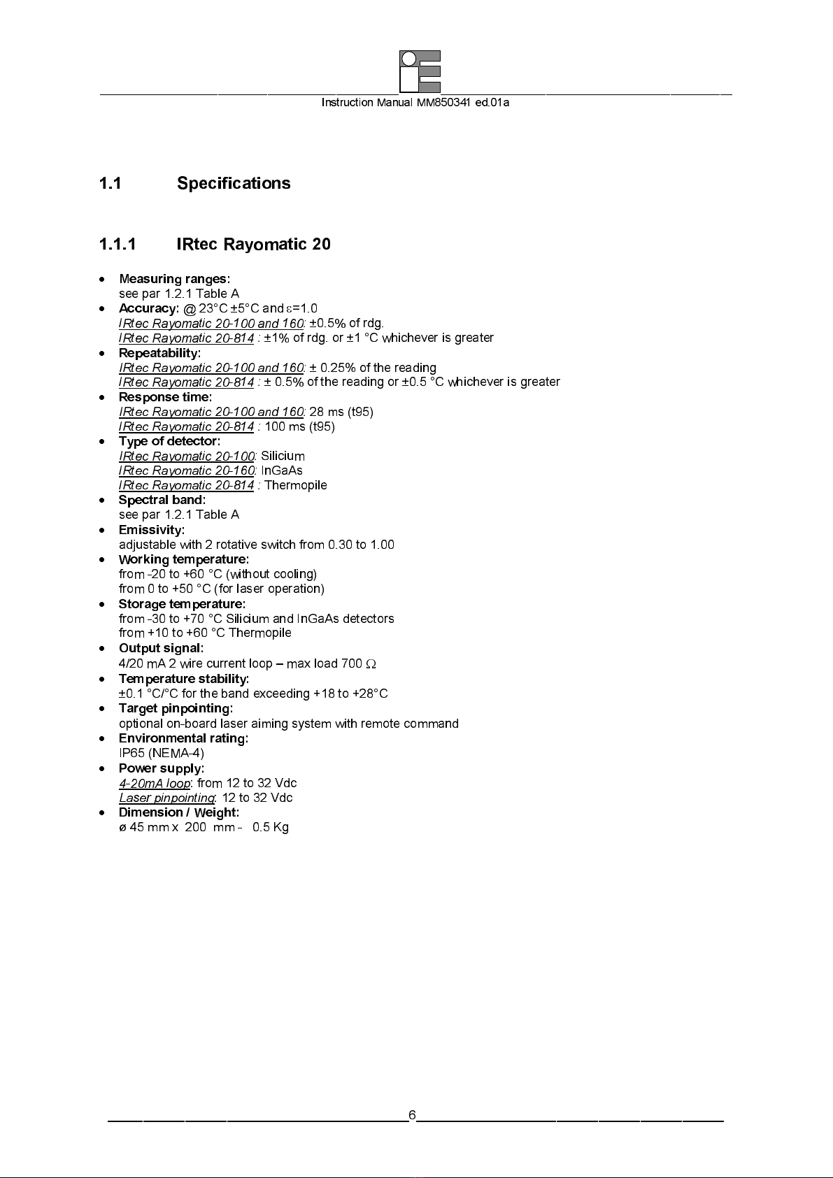
1.1 S ecifications
1.1.1 IRtec Rayomatic 20
•
Measuring ranges:
see par 1.2.1 Table A
•
Accuracy:
@ 23°C ±5°C and
ε
=1.0
IRtec Rayomatic 20-100 and 160:
±0.5% of rdg.
IRtec Rayomatic 20-814 :
±1% of rdg. or ±1 °C whichever is greater
•
Repeatability:
IRtec Rayomatic 20-100 and 160:
± 0.25% of the reading
IRtec Rayomatic 20-814 :
± 0.5% of the reading or ±0.5 °C whichever is greater
•
Response time:
IRtec Rayomatic 20-100 and 160:
28 s (t95)
IRtec Rayomatic 20-814 :
100 s (t95)
•
Type of detector:
IRtec Rayomatic 20-100:
Siliciu
IRtec Rayomatic 20-160:
InGaAs
IRtec Rayomatic 20-814 :
Ther opile
•
Spectral band:
see par 1.2.1 Table A
•
Emissivity:
adjustab le with 2 rotat ive swit ch fr o 0.30 to 1.00
•
Working temperature:
fro -20 to +60 °C (wit hou t cool ing )
fro 0 to +50 °C (for la ser operation )
•
Storage temperature:
fro -30 to +70 °C Sil ic iu and In GaAs detectors
fro +10 to +60 °C Ther opile
•
Output signal:
4/20 A 2 wire current loop – ax load 700
Ω
•
Temperature stability:
±0.1 °C/°C for the band exceeding +18 to +28°C
•
Target pinpointing:
optiona l on-boa rd laser ai in g sys te w ith re ote co and
•
Environmental rating:
IP65 (NEMA-4)
•
Power supply:
4-20mA loop
: fro 12 to 32 Vdc
Laser pinpointing
: 12 to 32 Vdc
•
Dimension / Weight:
ø 45 x 200 - 0.5 Kg

________________________________________________ _______________________________________________
Instruction Manual MM850341 ed.01a
___________________________________________7____________________________________________
Note:
•
Nominal target @ 95% energy
•
Optional laser pinpointing system not available on 814-5 and 814-6 models
When the laser pinpointing system is installed, m ltiply the act al target diameter by 1.2
________________________________________________ _______________________________________________
Instruction Manual MM850341 ed.01a
___________________________________________8____________________________________________
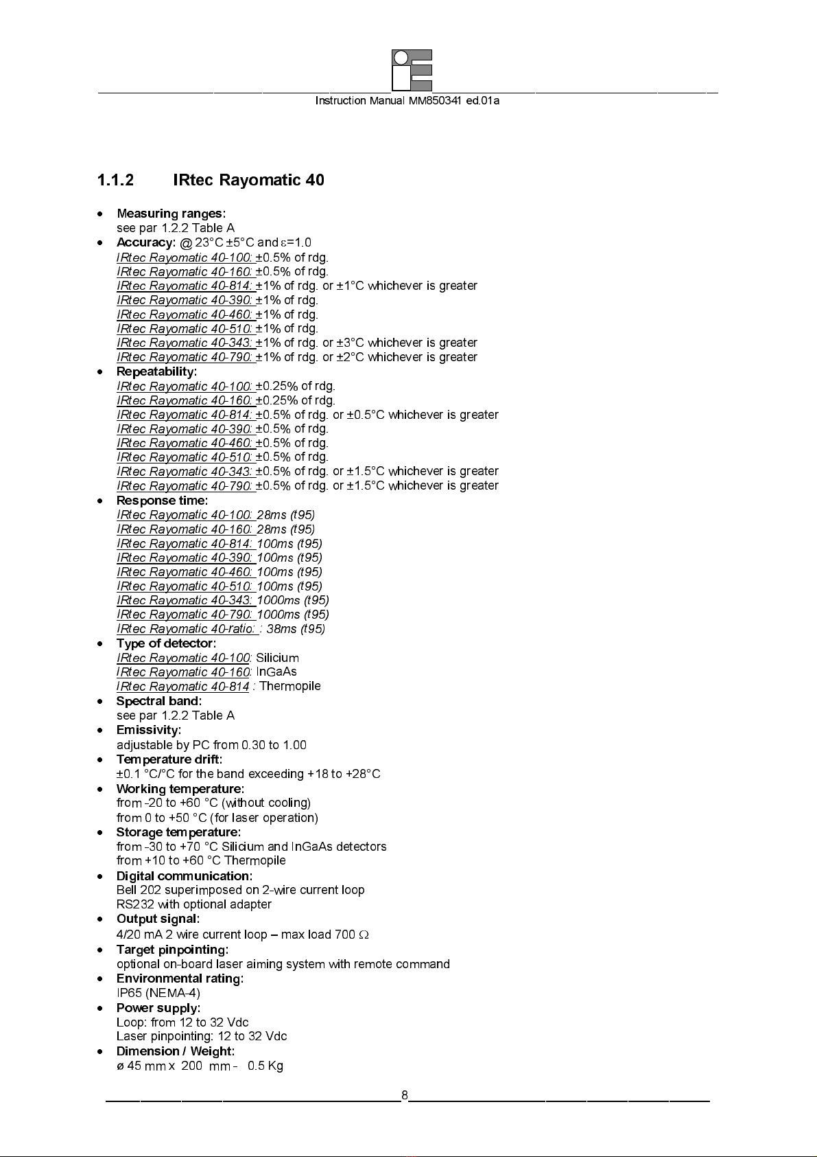
1.1.2 IRtec Rayomatic 40
•
Measuring ranges:
see par 1.2.2 Table A
•
Accuracy:
@ 23°C ±5°C and
ε
=1.0
IRtec Rayomatic 40-100:
±0.5% of rdg.
IRtec Rayomatic 40-160:
±0.5% of rdg.
IRtec Rayomatic 40-814:
±1% of rdg. or ±1°C whichever is greater
IRtec Rayomatic 40-390:
±1% of rdg.
IRtec Rayomatic 40-460:
±1% of rdg.
IRtec Rayomatic 40-510:
±1% of rdg.
IRtec Rayomatic 40-343:
±1% of rdg. or ±3°C whichever is greater
IRtec Rayomatic 40- 90:
±1% of rdg. or ±2°C whichever is greater
•
Repeatability:
IRtec Rayomatic 40-100:
±0.25% of rdg.
IRtec Rayomatic 40-160:
±0.25% of rdg.
IRtec Rayomatic 40-814:
±0.5% of rdg. or ±0.5°C whichever is greater
IRtec Rayomatic 40-390:
±0.5% of rdg.
IRtec Rayomatic 40-460:
±0.5% of rdg.
IRtec Rayomatic 40-510:
±0.5% of rdg.
IRtec Rayomatic 40-343:
±0.5% of rdg. or ±1.5°C whichever is greater
IRtec Rayomatic 40- 90:
±0.5% of rdg. or ±1.5°C whichever is greater
•
Response time:
IRtec Rayomatic 40-100: 28ms (t95)
IRtec Rayomatic 40-160: 28ms (t95)
IRtec Rayomatic 40-814: 100ms (t95)
IRtec Rayomatic 40-390: 100ms (t95)
IRtec Rayomatic 40-460: 100ms (t95)
IRtec Rayomatic 40-510: 100ms (t95)
IRtec Rayomatic 40-343: 1000ms (t95)
IRtec Rayomatic 40- 90: 1000ms (t95)
IRtec Rayomatic 40-ratio: : 38ms (t95)
•
Type of detector:
IRtec Rayomatic 40-100:
Siliciu
IRtec Rayomatic 40-160:
InGaAs
IRtec Rayomatic 40-814 :
Ther opile
•
Spectral band:
see par 1.2.2 Table A
•
Emissivity:
adjustab le by PC fro 0.30 to 1.00
•
Temperature drift:
±0.1 °C/°C for the band exceeding +18 to +28°C
•
Working temperature:
fro -20 to +60 °C (wit hou t cool ing )
fro 0 to +50 °C (for la ser operation )
•
Storage temperature:
fro -30 to +70 °C Sil ic iu and In GaAs detectors
fro +10 to +60 °C Ther opile
•
Digital communication:
Bell 202 superi posed on 2-wire current loo p
RS232 with optional adapter
•
Output signal:
4/20 A 2 wire current loop – ax load 700
Ω
•
Target pinpointing:
optiona l on-boa rd laser ai in g sys te w ith re ote co and
•
Environmental rating:
IP65 (NEMA-4)
•
Power supply:
Loop: fro 12 to 32 V dc
Laser pinpointing: 12 to 32 Vdc
•
Dimension / Weight:
ø 45 x 200 - 0.5 Kg

________________________________________________ _______________________________________________
Instruction Manual MM850341 ed.01a
___________________________________________9____________________________________________
Note:
•
Nominal target @ 95% energy
•
Optional laser pinpointing system not available on 814-5 and 814-6 models
•
When the laser pinpointing system is installed, m ltipy the act al target diameter by 1.2

________________________________________________ _______________________________________________
Instruction Manual MM850341 ed.01a
___________________________________________10____________________________________________
1.2 Ordering code
1.2.1 IRtec Rayomatic 20
cat. 1130 - A - B - C – D – E - F
Table A B CWL
φ
target/distance Range
100-1 0.9
µ
6 @ 500 600 to 1600°C (1100 to 2900°F)
100-2 0.9
µ
16 @ 1000 600 to 1600°C (1100 to 2900°F)
160-1 1.6
µ
6 @ 500 300 to 1300°C (570 to 2350°F)
160-2 1.6
µ
3 @ 300 300 to 1300°C (570 to 2350°F)
160-3 1.6
µ
2 @ 100 300 to 1300°C (570 to 2350°F)
814-1 8-14
µ
21 @ 600 -25 to 1000°C (-15 to 1800°F)
814-5 8-14
µ
80 @ 1000 0 to 800°C (32 to 1450°F)
814-6 8-14
µ
10 @ 65 0 to 400°C (32 to 750°F)
Table C Signal output
2 4÷20 A 2-wire current loop
Table D Pinpointing system
0 None
1 built-in laser pinpointing
Table E Electrical connection cable
1 2 long - 2 wires shilded
2 8 long - 2 wires shilded
9 Special lenght
Table F Report of Calibration
0 None
1 Eurotron NIST or EA traceable certificate with data

________________________________________________ _______________________________________________
Instruction Manual MM850341 ed.01a
___________________________________________11____________________________________________
1.2.2 IRtec Rayomatic 40
cat. 1140 - A - B - C – D – E - F
Table A B CWL
φ
target/distance Range
100-1 0.9
µ
6 @ 500 600 to 1600°C (1100 to 2900°F)
100-2 0.9
µ
16 @ 1000 600 to 1600°C (1100 to 2900°F)
160-1 1.6
µ
6 @ 500 300 to 1300°C (570 to 2350°F)
160-2 1.6
µ
3 @ 300 300 to 1300°C (570 to 2350°F)
160-3 1.6
µ
2 @ 100 300 to 1300°C (570 to 2350°F)
814-1 8-14
µ
21 @ 600 -25 to 1000°C (-15 to 1800°F)
814-5 8-14
µ
9 @ 300 0 to 1000°C (32 to 1800°F)
814-5 8-14
µ
3.5 @ 140 0 to 1000°C (32 to 1800°F)
814-5 8-14
µ
80 @ 1000 0 to 800°C (32 to 1450°F)
814-6 8-14
µ
10 @ 65 0 to 400°C (32 to 750°F)
22C-1 ratio 20 @ 1000 600 to 2000°C (1100 to 3630°F)
22C-2 ratio 6 @ 600 300 to 1 300°C (570 to 2350°F)
343-1 3.4
µ
26 @ 500 100 to 400°C (210 to 750°F)
390-1 3.9
µ
17 @ 550 600 to 1300°C (1100 to 2350°F)
460-1 4.6
µ
17 @ 550 400 to 1600°C (750 to 2900°F)
510-1 5.1
µ
17 @ 550 150 to 1300°C (300 to 2350°F)
510-2 5.1
µ
8.5 @ 300 800 to 2000°C (1470 to 3630°F)
790-1 7.9
µ
17 @ 550 40 to 600°C (104 to 1100°F)
Table C Signal output
2 4÷20 A 2-wire current loop with superi posed serial co unicat ion
Table D Pinpointing system
0 None
1 built-in laser pinpointing
Table E Electrical connection cable
1 2 long - 6 wires shielded
2 8 long - 6 wires shielded
9 Special length
Table F Report of Calibration
0 None
1 Eurotron NIST or EA traceable certificate with data
________________________________________________ _______________________________________________
Instruction Manual MM850341 ed.01a
___________________________________________12____________________________________________
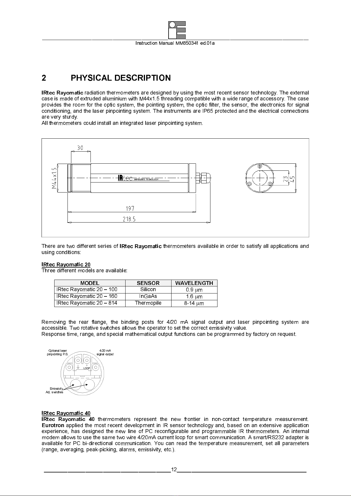
2 PHYSICAL DESCRIPTION
IRtec
Rayomatic
radiation ther o eters are designed by using the ost recent sensor technology. The external
case is ade of extruded alu iniu with M44x1.5 th reading co pat ib le with a wide range of accessory. The case
provides the roo for the optic syste , the pointin g syste , the opt ic fi lter , the sensor , the electronics for signa l
condit ion ing, and the l aser p inpo int ing sys te . The in st ru ents a re IP65 pro tected and the electrica l con nectio ns
are very sturdy.
All ther o eters could install an integrated laser pinpointing syste .
There are two different series of
IRtec Rayomatic
ther o eters available in order to satisfy all applications and
using conditions:
IRtec Rayomatic 20
Three different odels are avai lab le:
MODEL SENSOR WAVELENGTH
IRtec Rayo atic 20 – 100 Silicon 0.9
µ
IRtec Rayo atic 20 – 160 InGaAs 1.6
µ
IRtec Rayo atic 20 – 814 Ther opile 8-14
µ
Re oving the rear flange, the binding posts for 4/20 A signal output and laser pinpointing syste are
accessible. Two rotative switches allows the operator to set the correct e issivity value.
Response ti e, range, and special athe atical output functions can be progra ed by factory on request.
Emissivit
y
Adj. switches
Optional laser
pinpointing P.S. 4/20 mA
signal output
IRtec Rayomatic 40
IRtec Rayomatic 40
ther o eters represent the new frontier in non-contact te perature easure ent.
Eurotron
applied the ost recent develop ent in IR sensor technology and, based on an extensive application
experience, has designed the new line of PC reconfigurabl e and progra ab le IR ther o eters. An interna l
ode a l lows to use the sa e two wire 4/20 A current loop for s art co unic at ion . A s a rt /RS232 adapter is
available for PC bi-directional co unication. You can read the te perature easure ent, set all para eters
(range, averaging , peak-pi cki ng, alar s , e issi vi ty , etc.) .

________________________________________________ _______________________________________________
Instruction Manual MM850341 ed.01a
___________________________________________13____________________________________________
Two auxiliary lines can be progra ed a nd used for funct ion and ala r reset and to drive alar relè .
Four different odels are ava i lab le:
MODEL WAVELENGTH
IRtec Rayo atic 20 – 100 0.9
µ
IRtec Rayo atic 20 – 160 1.6
µ
IRtec Rayo atic 20 – 814 8-14
µ
IRtec Rayo atic 20 – X/Y X/Y
µ
HW Reset
Optional laser
pinpointing P.S. 4/20 mA
signal ou tput
A la rm output
________________________________________________ _______________________________________________
Instruction Manual MM850341 ed.01a
___________________________________________14____________________________________________
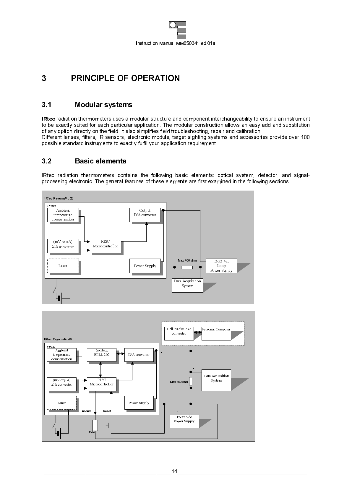
3 PRINCIPLE OF OPERATION
3.1 Modular systems
IRtec
radiation ther o eters uses a odular structure and co ponent interchangeability to ensure an instru ent
to be exactly suited for each particular application. The odular construction allows an easy add and substitution
of any option direct ly on the field. I t also si pl i fies f ield tro ubl eshooting , repair and cal ib rat ion .
Different lenses, filters, IR sensors, electronic odule, target sighting syste s and accessories provide over 100
possible standard instru ents to exactly fulfil your application require ent.
3.2 Basic elements
IRtec radiation ther o eters contains the following basic ele ents: optical syste , detector, and signal-
processing electronic. The general features of these ele ents are first exa ined in the following sections.
Ambient
temperature
compensation
(mV or
µ
A)
Σ
-
∆
converter
RISC
Mi crocontrollor
Power Supply 12- 2 Vcc
Loop
P ower Supply
Data Acquisition
System
O utput
D/A converter
IRtec Rayomatic 20
Pt100
Laser
M ax 700 ohm
Ambient
temperature
compensation
(mV or
µ
A)
Σ
-
∆
converter
RISC
Microcontrollor
Power Supply
12- 2 Vdc
Power Supply
Bell 202/RS2 2
converter Personal Computer
Reset
Modem
BELL 202
D/A converter
IR tec Rayomatic 40
Pt100
Laser
Allarm
Max 45 0 o hm
Data Acquisition
System
- +
+
+
Relè

________________________________________________ _______________________________________________
Instruction Manual MM850341 ed.01a
___________________________________________15____________________________________________
3.2.1 O tical system
The detector is positioned at a focus distance of a high quality lens. The lens for s an i age of the source in the
plane of the detector. The size of the cone of radiation accepted fro an axial point of the target and, the
irrad iance at the detector, is deter ined b y the clear aperture of the lens, while the active area o f the detector
deter ines the f ield of view. The lens and detector then act as the aperture and field stop of the syste
respectively.
3.2.2 Detectors
Thermopile
A ther opi le contain a large nu ber of ther ocouples in a very s all area. The ther ocouples are connected
together and the output is the difference between the a bient te perature (cold junction) and the te perature
collected by the optical syste (hot junction).
Inspite of la rge nu ber of ther ocouples, the signal outpu t is very s all: few
µ
V/°C. The response ti e of the
detector is very long because the detector ust be war i ng up (or coo led) by the collected energy.
The waveband is deter ined by an add it iona l op t ica l f i lter chose by Eurot ron for the speci fic app li cat ion . Th is
soluti on per its to reduce distu rbs due by at osphere absorpti on and to axi ise t he output signa l.
Photodiode
Both Siliciu and InGaAs photodiode principle is co pletely different fro ther opile: the collected energy is
transfor ed in a electron flow. The result is a current proportional with the incident energy.
This trans for a t ion is very fas t (onl y few
µ
S). This ti e the response ti e of the easuring syste is li ited by
electronics: high resolut ion and low energy con su pt ion , ak e it a lit tle bi t slower.
The waveband is deter ined by the phys ica l charac teris t ic of the sensor.
Ratio detectors
Special IR ap pl ica t ions could no t be so lved us ing the stan dard onochr o at ic ther o eters. A ratio detector
could be the solution.
Typical proble s which wil l cause an inco rrect reading inc lud e:
•
s all objects e.g. to s all to fill the target area
•
s oke, dust or stea which obscure the line of sight
•
dirty windows in the process
•
e issivit y of the produc t changes (due to changes in al loy or surf ace condi tio n) .
A ratio detector is a sing le chip tw in detector wi th di fferent worki ng wavelengths. The rat io of the two si u lta neous
easure ents is independent fro e issivity and the result is the correct target te perature.
Every ratio ther o eter has a li it as to how uch signa l can be lost. Th is is referred as t he reducti on ra t io that
can vary up to 90% without effecting the easure ent accuracy. To be also kept in consideration that the loss in
signal can co e fro 3 sources:
•
low e issivi ty of the target
•
object too s all to f il l the co ne of visi on
•
obstruction caused by stea , s oke, dirt and dirty windows
In all the above condition a ratio ther o eter will operate with better accuracy than any onochro atic
ther o eter. The IRtec “Rayo atic” ther o eters was designed to operate with spectral bands with li ited
te perature coefficient.
3.2.3 In ut stage
Is the ost i portant part of the ther o eter. It should be able to interface the detector to the icro-controller.
IRtec Rayo atic series uses different kind of detectors (ther opile, photod iode, and ra t io detectors) with dif ferent
operating specifications.
•
Ther opile odels needs electronics with high i pedance input and very low drift.
•
Photodiode odels needs fast electronics .
•
Ratio odels needs electronics able to drive a double detector.
For the best odula ri ty of the easuring syste , Euro tron has developed special configu rab le electronics to eet
all require ents.

________________________________________________ _______________________________________________
Instruction Manual MM850341 ed.01a
___________________________________________16____________________________________________
3.2.4 Microcontroller
Microcontroller has to anage all ther o eter functionality. It should be fast, with low absorption, with integrate
e ory, serial interface, etc.
Eurotron’s IRtec Rayo ati c use a R ISC processor with intern al re-wr ita ble FLASH e ory.
3.2.5 Serial communication
This odule is included in
IRtec Rayomatic 40
only. This odule consist of a special ode to i ple ent serial
co unica t ion on the ther o eter.
The s art IRtec Rayo at ic l ine uses a digi ta l co unic at ion ethod superi posed on the 2 w ire 4-20 A loop to
co unica te with PC, lap- top and/or handheld co unica to rs.
The co unicat ion capab i li ty also eans that a PC can be used both for re o te calibra tio n and tra ns i tter
operative ode configuration.
The digital protocol operates using the frequency shift keying (FSK) principle, which is based on the Bell 202
co unica t ion sta ndar d where si ne waves are superi posed on the dc analog signa l to gives si u ltaneous
analog and dig ital co unica tion
Te perature unit , peak hold , e issiv it y, average ca n be p rog ra ed thro ugh the dig ita l port using either a PC or
a dedicated co unica tor.
3.2.6 Out ut stage
This odule is based by a D/A converter to transfor t he te perature easure ents fro the icrocontroller
digita l for at to the cur rent s igna l. The sign al output fro t he ther o eter is a 4/ 20 A on 2-w ire cur rent loop
linear with the te perature range.
3.2.7 Tem erature com ensation
All IR detector are a bient te perature sensible. Detectors easure the difference between detector and target
energy. To obtain the correct value of target te perature, it is necessary to easure the detector te perature
and add it to the detector easure ent. A Pt100 is ounted on the detector and icroco ntroller reads the
te perature and akes the co p uta tion.
3.2.8 Power su ly
A power supply s tage is bu il t- in the ther o eter for adaptin g the current loop supp ly ( f ro 12 to 32 Vdc) to al l
digital and analogue circuits.
3.2.9 Laser in ointing
IRtec Rayo atic ther o eters can be optionally equipped with a laser pinpointing syste to si plify aligne ent
operation.
When target has s all and cr it ica l di ensi ons the laser ai i ng syste can be activated by operator to check and
adjust appropriate align ent of ther o eter.
A separate (12-32 Vdc ax. 100 A) power supply input all o ws operator to use it only when necessary.
3.2.10 Laser in ointing
IRtec Rayo atic ther o eters can be optionally equipped with a laser pinpointing syste to si plify align ent
operation.

________________________________________________ _______________________________________________
Instruction Manual MM850341 ed.01a
___________________________________________17____________________________________________
4 SIGNAL PROCESSING
When a radiation ther o eter is e ployed in an on-line syste , its signal ay be subjected to large fluctuations.
Ti e function facilities are useful to retain the signal levels that are ore likely to represent the true target
te perature.
Eurotron IR ther o eters can be fa cto ry pre-set wi th one of the signal p rocessi ng facil i ties: averag ing , T rac k &
Hold, Peak, Valley, Peak-Picking, Valley-Picking, etc.
IRtec Rayomatic 40
functions can be progra ed fro user by using a Personal Co puter, a Bell202/RS232
adapter and a configuration software.
IRtec Rayomatic 20
Average function can be p rogr a ed by fact ory only .
4.1 Average
Rapid te perature fluctuations about a true ean value can ake the ther o eter output unsuitable for
recording and cont ro l. In t hese cases the average fun ct ion c an be used to p rov ide a s oo thed s igna l . The ou tpu t
signal Avu is given by:
Avu =Avp + (M – Avp) * 2
∆
T / D
where:
M
= Actual te perature
Avu
= Output average
Avp
= Previous average
∆
T
= sa pling ti e
D
= Da ping in seconds (progra able)
Temperature
Temperature with constant D>0
Range 0..99
Actual temperature
(D=0)
Time
4.2 Peak
The Peak function holds a axi u te perature and retain i ts unt il a h igher va lue appear o r an external reset
signal appear to decay the output to the current te perature easure ent.

________________________________________________ _______________________________________________
Instruction Manual MM850341 ed.01a
___________________________________________18____________________________________________
4.3 Valley
The Valley function holds the ini u te perature and retain its until a lower value appear or an external reset
signal appear to increase the output to the current te perature easure ent.
4.4 Peak-Picker
The peak-picker function holds a peak signal and allows it to decay slowly until the arrival of the next peak. It is
used in such appli cat ion s as ro l lin g il ls where the signa l is o ccas iona l ly lowered by stea , s oke, water
droplets, etal scale, etc. When Peak-Picker function is progra ed, the 4/20 A output will follows the
athe atical expression below:
U = Peak – (PickDec * 2
∆
T)
dove :
U
= output signal
Peak
= peak signal
PickDec
= D ecay rate °C/sec (progra able)
∆
T
= sa pling ti e
Temperature
Time
Decay rate (PickDec)
Programmable (0.0 to 1999.9 °C/S)
4.4.1 Peak-Picker with reset
When the Peak-Picker with reset function is selected, the external reset input is used to force the signal output to
the current te perature easure ent.
________________________________________________ _______________________________________________
Instruction Manual MM850341 ed.01a
___________________________________________19____________________________________________
rese
t
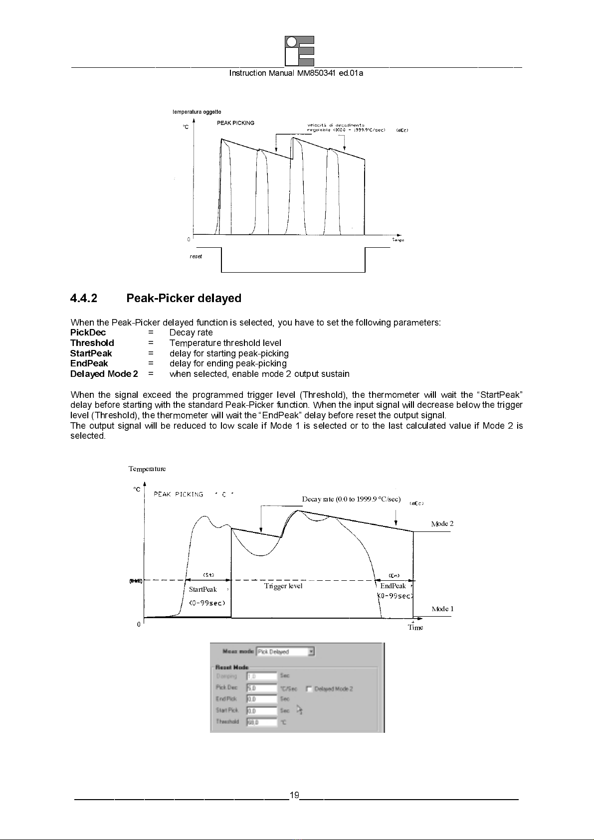
4.4.2 Peak-Picker delayed
When the Peak-Picker delayed function is selected, you have to set the following para eters:
PickDec
= Decay rate
Threshold
= Te perature threshold level
StartPeak
= delay for starting peak-picking
E dPeak
= delay for ending peak-picking
Delayed Mode 2
= when selected, enable ode 2 output sustain
When the signal exceed the progra ed trigger level (Threshold), the ther o eter will wait the “StartPeak”
delay before starting with the standard Peak-Picker function. When the input signal will decrease below the trigger
level (Threshold), the ther o eter will wait the “EndPeak” delay before reset the output signa l .
The output signal will be reduced to low scale if Mode 1 is selected or to the last calculated value if Mode 2 is
selected.
Temperature
Time
Decay rate (0.0 to 1999.9 °C/sec)
Trigger level
StartPeak E dPeak
Mode 1
Mode 2

________________________________________________ _______________________________________________
Instruction Manual MM850341 ed.01a
___________________________________________20____________________________________________
4.5 Valley-Picker
Reverse the Peak-picker function principle to describe the Valley Picker.
U = Valley + (PickDec * 2
∆
T)
where :
U
= output signal
Valley
= Valley signal
PickDec
= Increasing rate °C/sec (progra ab le)
∆
T
= sa pling ti e
4.5.1 Valley-Picker with reset
Reverse the Peak-Picker with reset function principle to describe the Valley-Picker with reset.
4.6 Track and Hold
The track (sa ple) and Hold func t ion al lows s oothed signal s to be ob tai ned fro inter i t tent events. These ay
origina te fro objects on a conveyor belt or targets where the view is periodic al ly obscu red by rotat ing achinery .
The output sa pl ing is act iva ted by a co and signa l received by an external switch tha t can be actuated by the
belt or rotating ach inery itself. The outpu t is held when the swi tch is operated unt i l t he next co and i s
received.
Time - temp o
Temp.
R
eset
Track & Hold
This manual suits for next models
1
Table of contents
Other Eurotron Thermometer manuals


