ACD CAL 2000 LT User manual

Cal 2000 LT
Gas Generator
INSTRUCTION MANUAL
Cal 2000 LT
ACD
2024 W. McMillan Street
Tucson, Arizona 85705 •U.S.A.
Telephone: (520) 290-2855 •Fax: (520) 290-2860
E-mail: [email protected]
Advanced Calibration Designs, Inc.
Revision - 040525 www.goacd.com
Advanced Calibration Designs, Inc.
ACD
Release I

Instruction Manual
Cal 2000 LT
Gas Generator
TABLE OF CONTENTS
I. General Description Page2
II. Normal Operation Page7
III. Menu Options Page11
IV. Maintenance Page12
V. Troubleshooting Page13
VI. Standard Warranty Page15
VII. Accessory Items / Parts List Page17
VIII. Instrument Specifications Page19
Manufactured by:
Advanced Calibration Designs, Inc.
2024 W. McMillan Street
Tucson, Arizona 85705 USA
Phone: 520 290 2855 - Fax: 520 290 2860
Int'l Phone: 001 520 290 2855 - Fax: 001 520 290 2860
Chlorine(Cl2)......................................................................1-25ppm
Hydrogen(H2).....................................................................1-25ppm
HydrogenCyanide(HCN)................................................1-25ppm
HydrogenSulfide(H2S)....................................................1-25ppm
(ppm concentration must be specified when ordering cell)
AirFlowRate..................................................................0.5or1.0LPM
(flowrate must be specified when ordering CAL 2000 LT)
Warm-up time (to 90%)................Approximately 5 minutes
L x W x H........................8.5 x 4.25 x 3.0” (21.6 x 10.8 x 7.6 cm)
Weight...................................................................3 lbs. (1360 g)
Operating Temperature.......................................0° C to 50° C
Relative Humidity (intermittent use).............................0 -100%
Accuracy.............................................................±10%
Repeatability...................................................±5%
Battery Power.........................................................4 alkaline “C”
BatteryLife.................................................................................10hours
CSA Certified Instrinsically Safe
Class I, Division 1, Groups A, B, C & D
European Standards approval for Zone 0
SPECIFICATIONSVIII.
Page 19

WARNING:
This instrument generates calibration gas for toxic
gas detectors. The instruction manual should be
read and understood prior to operation of the
instrument. Failure to operate the instrument
correctly can lead to improper calibrations.
This instrument conforms to the protection requirements of the EC
DIRECTIVE 89/336/EEC on Electromagnetic Compatibility (EMC),
in accordance with the provisions of Statutory Instrument 2372.
The following standards have been applied:
EN 50081-1
Emissions Standard (Residential Commercial and Light Industry)
EN 50082-1
Immunity Standard (Residential Commercial and Light Industry)
Page 18
700-0600-03 Pump, Low Flow Rotary Vane, 6 VDC
715-0403-0X 3 Foot Hose w/connector, low flow,
1/4" OD
715-0405-0X 5 Foot Hose w/connector, low flow,
1/4" OD
730-0615-00 Hard-body, Water Resistant, Padded
Carrying Case
910-0603-LT Instruction Manual

I. GENERAL DESCRIPTION
The Cal 2000 LT is a battery-powered, portable electrochemi-
cal gas generator designed to calibrate toxic gas sensors.
Fast warm-up time allows the instrument to be turned off
between remotely located sensors saving battery life and
avoiding generation of unwanted gas. A built-in mass flow
sensor provides accurate flow control to insure proper cali-
bration gas concentrations. The Cal 2000 LT uses the fol-
lowing components to produce the calibration gas/air mix-
ture:
Internal Micro Pump
A small, rotary vane, micro air pump draws in ambient air to
blend with the generated gas.
Electrochemical Generating Cell
The electrochemical generating cell contains an electrolyte
solution and either inert or consumable electrodes, depend-
ing upon the gas being generated. A precise concentration of
gasis produced when aknown amount of currentand a known
amount of air is supplied continuously to the cell. Each cell
has a built-in memory chip that tells the Cal 2000 LT instru-
ment what type and concentration of gas is to be generated
and how much cell life is remaining. The electronics board
mounted to the cell should never be removed from the cell.
Removal of this board will void warranty and destroy the cell.
Due to the design characterization of the cell, the unit must be
oriented flat (on the units feet) for correct concentration out-
put.
Page 2Page 17
Accessory Items / Parts List
The following items are available as accessories for the
CAL 2000 LT:
P/N Description
113-0402-00 Male Hose Barb Quick Connector, 1/8"
OD hose
150-4121-00 Charcoal Filter Element, one
each
150-4131-00 Charcoal Filter Element,
package of 12
362-0600-00 ACAdaptor, 115 VAC, US style plug
7.5VDC, 300 mA
400-0600-LT Main Circuit Board Assembly
400-0703-00 Power Circuit Board Assembly
510-2000-LT Chlorine Cell
510-2050-LT Hydrogen Sulfide Cell
510-2070-LT Hydrogen Cyanide Cell
510-2090-LT Hydrogen Cell
VII.

Cell Installation and Removal
There are no tools required by the end user for ser-
vice of the instrument. The electrochemical cells
are shipped seperate of the unit and should be in-
stalled on receipt. To install the cell, remove the bottom
cover of the instrument. This is done by pulling each of the
‘plunger feet’ on the bottom of the instrument. Once all of
the plungers have been pulled out, the bottom cover is sim-
ply removed from the instrument.
The cell is keyed to ensure proper alignment into the in-
strument. When installed, the circuit board of the cell should
be flat with the bottom of the instrument. Push up on the
clear window at the back of the instrument to eject the cell.
Page 3 Page 16
warranty of fitness for a particular purpose. In no event
shall Advanced Calibration Designs, Inc. be liable for
direct, incidental or consequential loss or damage of any
kind connected with the use of its products or failure of its
products to function or operate properly.
The following is a listing of the available electrochemical
Cal 2000 LT cells and their standard warranty when
installed in equipment manufactured and supplied by
Advanced Calibration Designs, Inc.
10 Hour Generating Cells
1. Chlorine - One year or 10 hours of use.
2. Hydrogen Sulfide - One year or 10 hours of use.
3. Hydrogen Cyanide - One year or 10 hours of use .
4. Hydrogen - One year or 10 hours of use .
25 Hour Generating Cells
1. Chlorine - One year or 25 hours of use.
2. Hydrogen Sulfide - One year or 25 hours of use.
3. Hydrogen Cyanide - One year or 25 hours of use .
4. Hydrogen - One year or 25 hours of use .

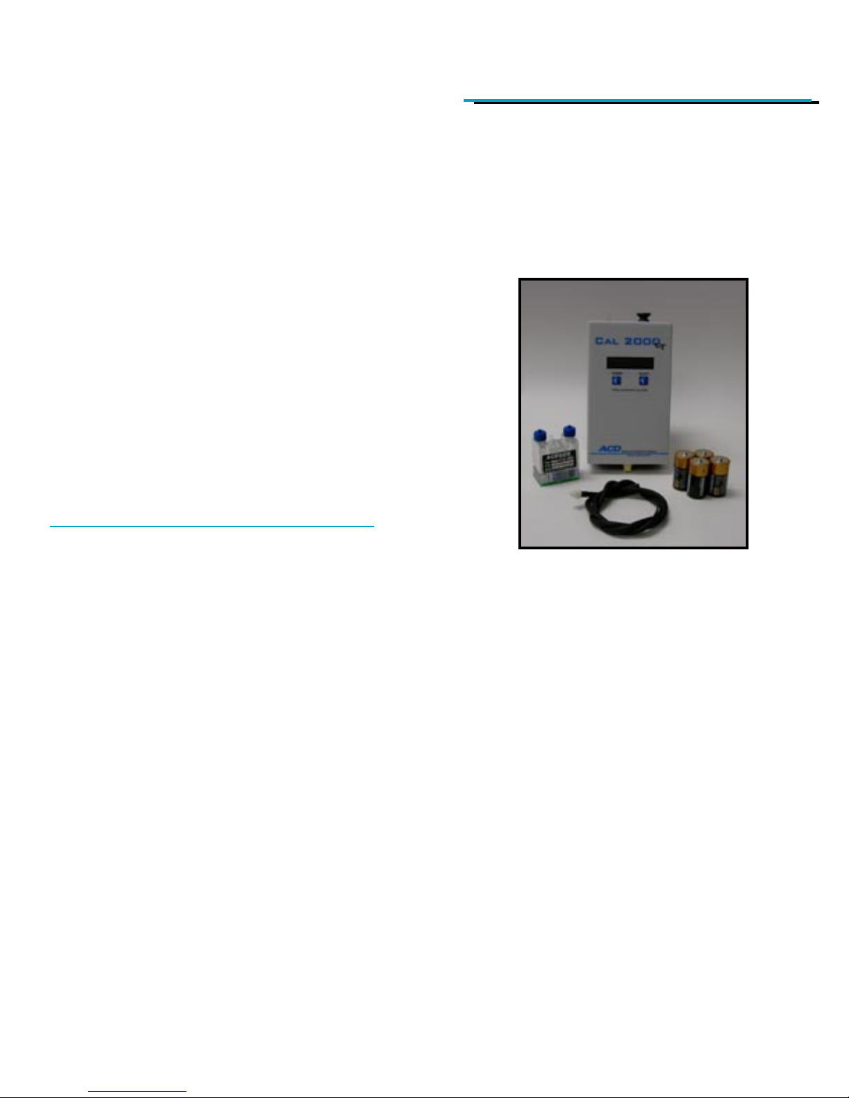
Alkaline "C" Batteries
A set of four fully charged, heavy duty alkaline "C" batteries
provides approximately 10 hours of operation. Note: Re-
chargeable or light duty batteries can be used, but they
give significantly less operating time. Using re-chargeable
batteries will also void the CSA safety certification during
the time of their use.
Microprocessor-Based Circuitry
The Cal 2000 LT has microproccessor based circuitry that
performsseveral different operations andoffers the usermany
different features. The microprocessor tracks cell and battery
usage,monitors theair flow rateand controlsthe cell andpump
to give the correct ppm and flow rate. In addition to English,
every Cal 2000 LT is capable of providing menu displays in
French, German and Spanish. See section III. Menu Options
for instructions on how to change the menu language.
Digital Display
The Cal 2000 LT has a liquid crystal display (LCD) located on
the front of the instrument. This display is protected by a thin,
clear plastic cover that is part of the front label and may be
replaced if it becomes scratched or unclear.
POWER and SELECT
The POWER and SELECT switches are momentary push but-
tontype switches activated throughthe front membranepanel.
They are physical switches mounted directly on the circuit
board.
Delivery Hose
The instrument comes standard with a three (3) foot long,
¼inch diameter norprene hose for delivering the gas to the
sensor or calibration adapter. The hose has a male quick
connect adapter for easy attachment to the instrument.
Page 4Page 15
VI. Standard Warranty
We warrant gas calibration equipment manufactured and
sold by us to be free from defects in materials, workmanship
and performance for a period of one year from date of
shipment. Any parts found defective within that period will
be repaired or replaced, at our option, free of charge, F.O.B.
factory. This warranty does not apply to those items which
by their nature are subject to deterioration or consumption in
normal service, and which must be cleaned, repaired, or
replaced on a routine basis.
Such items may include, but are not limited to:
a. Electrochemical type generating cells
b. Electrolyte
c. Batteries
Warranty is voided by abuse including rough handling,
mechanical damage, alteration, or repair procedures not in
accordance with the instruction manual. This warranty
indicates the full extent of our liability, and we are not
responsible for removal or replacement cost, local repair
costs, transportation costs or contingent expenses incurred
without our prior approval.
Advanced Calibration Designs, Inc.'s obligation under this
warranty shall be limited to repairing or replacing, and
returning any product which shall be returned to Advanced
Calibration Designs, Inc. at its manufacturing facilities, with
transportation charges prepaid, and which Advanced
Calibration Designs, Inc.'s Material Review Board examina-
tion shall disclose to its satisfaction to have been defective.
This warranty is expressed in lieu of any and all other
warranties and representations, expressed or implied, and
all other obligations or liabilities on the part of Advanced
Calibration Designs, Inc. including, but not limited to, the

Page 5 Page 14
Nylon Carrying Case
The Cal 2000 LT comes with a convenient, durable, nylon
carrying case. It is adjustable to be worn as a hip pack, or the
belt strap can be reattached to be worn around the neck or
over the shoulder. The top of the carrying case is clear plas-
tic, allowing the unit to be operated while within the case, and
there is a convenient front pocket for storage of additional
cells or the delivery hose.
Mass Flow Sensor
The Cal 2000 LT has a built-in mass flow sensor that mea-
sures the flow rate of the instrument. This information is
used to control the pump to provide the desired flow-rate.
The flow meter should be calibrated against a primary mass
flow standard every 12 to 24 months.
Internal Charcoal Filter
An internal charcoal filter is provided to scrub contaminated
air and provide a clean baseline for the calibration gas
generated. This filter should be replaced on a yearly basis
and is removed by pulling out the grey plunger at the top of
the unit. Spare filter elements can be purchased through
ACD. Note: The charcoal filter must be fully installed into
the instrument for correct operation.
"Cell Failure!"
accompanied by an audible beep.
There are two possible causes for a cell failure. One
cause is that the instrument has not detected a cell. The
other is that a high voltage has been detected across the
cell.
If the cell is not initially detected by the processor, the unit
will display cell failure and immediatly shut down (without
entering ‘purge mode’). This failure can happen either
because a cell is not inserted, connection to the cell is not
made, or due to a failure of the circuit board on the generat-
ing cell.
The cell failure alarm will also engage if the microproces-
sor detects an abnormally high cell voltage condition. One
possibility for this high voltage is that one of the pins may
be making a faulty electrical connection. Another possibility
is that the electrolyte level is too low. For instructions on
how to replenish the electrolyte refer to
Section V: Maintenance.
If this message continues after the cell has been plugged
in correctly and the electrolyte level has been confirmed to
be sufficient, contact the factory and/or replace the cell.
"Cell is used up! “
accompanied by an audible beep.
The cell life has expired and the display will show no time
remaining on the cell.

Page 6Page 13
Optional items available for the Cal 2000 LT include:
AC Adapter
The Cal 2000 LT may also be operated from anAC adapter.
The AC adapter converts the AC voltage supplied from the
main power lines to 6 VDC which is used in lieu of the bat-
teries. The adapter plugs into the instrument from the un-
derside of the case directly into the power board and is in-
dependent of polarity. If needed, contact the factory for
exact specifications of the AC adapter.
Hard Body Instrument Case
A water resistant, padded instrument case is available for
storage and shipping of the Cal 2000 LT. The case is
made out of rugged, high impact resistant plastic and will
help protect the instrument in harsh environments. The
foam insert may be customized to hold additional items
like spare batteries and cells.
Extension Hoses
Longer sample hoses may be purchased for use with the
Cal 2000 LT in lengths up to 20 feet. Note: the internal
pump may not be capable of overcomming flow restricions
associated with extreme hose lengths when operating at
1.0LPM.
Troubleshooting
No Power To Instrument
There are two common causes for the unit to not power
up when the POWER switch is pressed for three sec-
onds.
The most common is that the batteries are dead. Try
replacing the batteries with new alkaline batteries or try
powering the unit from the AC power adapater.
The second most frequent cause for no power to the
instrument is a blown protective fuse. This fuse can be
shorted out if the batteries have been removed from
the instrument with a metallic object such as a
screwdriver. If the protective fuse has been blown
contact the factory.
"Battery is low!"
accompanied by an audible beep.
If battery power drops below 5% capacity, the screen will
flash "Battery is low!". Replace the batteries or switch to
AC power.
"Flow too low" / "Flow too high"
accompanied by an
audible beep.
Accurate air flow is critical to an accurate gas mixture.
The microprocessor and built-in precision mass flow
sensor continuously monitor the air flow. If, however, a
flow problem develops (e.g. air blockage or kinked
tubing) which cannot be corrected within ten seconds,
the unit will display "Flow too low." If the problem cannot
be cleared after an additional minute, the instrument will
enter the purge mode and then power down.
V.

Page 7 Page 12
II. Normal Operation
To start the generator, press and hold the POWER switch,
located in the middle left front of the instrument, until the
display reads A. C. D., approximately three (3) seconds.
Release the switch immediately thereafter.
The instrument will sequence through several screens as
follows:
Please Note: If you would like to change the language of
the menus, see section III. Menu Options: Foreign
Language Option, for instructions.
The instrument will display the Serial Number and Cell
Number, followed by the manufactured date.
A. C. D. I
Copyright2003
Calibration Date
01Aug 2004
Manufactured
01Aug 2003
Serial# 0000001
Cell # 000001
IV. Maintenance
The electrochemical cells of the CAL 2000 LT require
periodic maintenance to provide optimum performance. It is
recomended that the electrolyte solution be replaced on an
annual basis.
If the instrument is returned with the cell on an annual basis
to maintain NIST certification, the electrolyte will be replaced
bythe factory.
The following steps should be taken to replace electrolyte.
........a. Remove cell as described in section I. General
Description: Cell Installation and Removal.
........b. Unscrew solid fill plugs on reservoir and
remove liquid.
........c. Use syringe (provided with electrolyte) to add
liquid to within 1/8 inch from the bottom of fill hole.
Warning: Do not over-fill reservoir. Trapped air must be
allowed to escape through vent plug as fill screw is
replaced. Contact the factory for more information.
........d. Replace fill plugs.
The electrolyte in the electrochemical cells can also dehy-
drate over time in dryer climates. Alow electrolyte level will
ultimately result in a “Cell Failure” warning. Since only water
is evaporated, and the electrolyte salts are remaining in
solution, it is only necessary to replenish the electrolyte with
distilled or de-ionized water. Ordinary tap water (as well as
many bottled waters) should not be used as it contains
chemicals and minerals that could contaminate the cell.
Replenishing the cell with water is similar in procedure to
replacing the electrolyte shown above, but the remaining
electrolyte is not removed before the replenishment water is
added.

The Calibration Date refers to when the instrument itself
was last calibrated at the Factory. It does not refer to the
calibration date of the generating cells, which are field
replaceable.
The following status screens indicate the remaining cell
life, battery status and flow-rate.
Immediately after the flow rate screen appears, the ppm
screen appears.
Page11 Page 8
CellLife
009 Hrs 59 Mns
Battery Status
100% remaining
Flow:0.5lpm
Output: 5 ppm
III. Menu Options
Foreign Language Option
The menu options can be adjusted to read in German,
French, or Spanish. To change the language, start the unit as
you normally would. When the ACD screen appears,
press the SELECT button. This will bring up the following
screen:
Press the SELECT button to choose the preferred language.
When the language is displayed, press the POWER button to
continue with the start up sequence.
Flow-Rate Select Option
The CAL 2000 LT is shipped from the factory set at either 0.5
LPM or 1.0 LPM depending on what was specified when the
unit was ordered. To change this in the field the following
screen can be used.
Note that the CAL 2000 LT cells read this setting on the in-
strument and will work correctly at either flow-rate.
A. C. D. I
Copyright2003
English
SELECTtochange
SelectFlow Rate
0.5 LPM 1.0 LPM

Page 10Page 9
5 ppm CL2
Standby: 145sec
Stabilizing ...
Standby: 146 sec
Flow: 0.5 lpm
Standby: 144 sec
Once the flow and concentration have been displayed, the
instrument will enter the stabilization period and the display
will alternate between the following three screens:
When the instrument has finished counting down to zero
(0) seconds, it has reached 90% of its final output and will
enter the gas generating mode. In this mode, the instru-
ment will display the gas being generated, the flow rate, the
ppm setting and the time while running at these settings as
follows:
CL2 @ 0.5 lpm
5ppm 00:00:07
When you are finished generating gas and wish to turn off
the instrument, press and hold the POWER switch until the
purge screen is displayed.
]
The instrument will purge itself of gas for 300 seconds and
then automatically shut off. At any time during this period,
you may turn the instrument back on by pressing the
SELECT switch and entering the status screens as described
above. You must change either the flow rate or the ppm
setting and then the instrument will immediately go to the
stabilization screen and continue to run at the new settings.
The amount of stabilization time will depend upon how long
the instrument was in the purge mode.
Purging ...
Standby: 300 sec
Other ACD Test Equipment manuals
Popular Test Equipment manuals by other brands

Fluke
Fluke ScopeMeter 190-104 datasheet

BACtrack
BACtrack BREATH ALCOHOL DETECTOR owner's manual

JDS Uniphase
JDS Uniphase OneExpert DSL user guide

Bibby Sterilin
Bibby Sterilin TECHNE Tecal 140S Operator's manual

UCL SWIFT
UCL SWIFT TEK-6 quick start guide

Lovibond
Lovibond Tintometer TB 350 quick start guide

az-instrument
az-instrument 8930 Operation manual

Keysight Technologies
Keysight Technologies N5990A-301 user guide

HT
HT MPP300 user manual

Sensitron
Sensitron MULTISCAN++/S2-16 Installation and use manual

Aeroflex
Aeroflex RGS-2000NG Getting started manual

Extech Instruments
Extech Instruments TK36 owner's guide