Acdeos AXS MD SA Series User manual

Condensed Manual
AXS MD ….. SA (mechanical step)
ACDEOS BV
Touwbaan 1A
2352 CZ Leiderdorp
Netherlands
WWW.ACDEOS.COM
Date: jul 2018
Rev. 2.1
AXS–MD Step

2
1Technical specifications
Product description Foot operated step for mounting outside under the floor of a
vehicle.
Installation Under the vehicle Floor at the front- middle or rear door
Dimensions Step depth 300 mm - width depending on model 600, or 900 mm
For detailed dimensions please refer to the installation drawings
in the rear of the manual.
Weight total AXS MD 600 M = 16 Kg
AXS MD 900 M = 20 Kg.
Load Maximum load 150Kg (1500 N)this is always labeled on theStep.
Materials Frame; steel with EP corrosion protection and aluminum sliding
profile,
Step: Aluminum profile and plastic corner pieces.
Life cycle Tested life cycle of the step is 100.000 cycles with a load of 100
KG.
Electrical connection Waterproof 2 pin connector (IP65) on the step.
Electric signals Step closed
Legislation The product fulfils R107 UN Bus directive and 98/37 EC Machine
directive.

3
2Safety instructions
These Safety instructions should always be kept with the step. The
operator must be made aware of these instructions before operating
the Step. Read and follow these safety instructions carefully.
The step is intended to be an extra step to enter a vehicle. It should be used appropriately by
passengers to enter or exit a minibus, taxi camper or other vehicle, and the maximum load
should not be exceeded.
1. Before operating the step the vehicle must be stationary and the hand brake
or parking brake must be applied.
2. Before operating the step, ensure that there is nothing obstructing it. Look out
for people moving outside the vehicle near the step.
3. It is recommended that the step is only operated by the driver or other
qualified operators.
4. The driver or operator must have a clear view of the step when they are
operating it.
5. It is recommended that the middle of the platform is used when stepping onto
the step.
6. NEVER drive away when the RED dashboard LED light is still on, this means
that the step is not properly stowed.
7. The step platform must be kept clean and free of oil and other greasy
materials.
8. If there is any doubt about the safety of a passenger when using the step,
ensure they are assisted.
9. If you have any questions about the safe operation of the step, contact the
person responsible directly.
10. Never use the step for any other use than described here.
11. Never overload the step.
12. The step should always be operated until it is fully in or out.
13. Repair and maintenance must be done by qualified and trained staff only.
14. If any parts need replacing, ensure only original Acdeos Parts are used.
15. If the anti slip profile on the step becomes worn, the step platform must be
replaced.
16. Always use the recommended cleaning materials.
17. Report any unsafe aspects of the step to the step supplier.

4
3Operation
First read safety instructions
This is a mechanical semi-automatic step. You can operate the step by feet.
To open the step; simply push with your feet at the
center of the step. The step will move in a little and
unlock itself. Take away your feet and the step will
come out automatically.
To close the step: push with your feet at the center
of the step until the step is completely closed. The
step will lock automatically.

5
4Installation
The installation must only be done by a company that is familiar with bodybuilding or modifying
vehicles, and that have the trained technical staff.
4.1 Mechanical Installation
Below instruction is based at mounting the step with the optional flexi fit mounting kit which is
available under number S130 01 024. Ask your dealer for availability
In order to mount the step you do not need to make any major vehicle adaptations. The step
is placed under the floor in the middle of the front, middle or rear door. Chassis modifications
are not needed, but you may need to remove some plastic underbody parts.
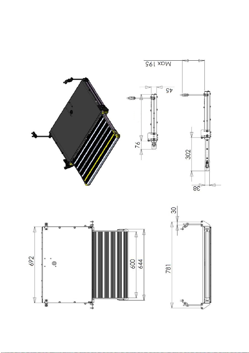
Exact measurements of the product should be taken from the official installation drawings. Ask
Acdeos for the last revision and official installation drawing. Figures and drawings in this
manual are only indicative.
Installation:
Create a safe working environment. Raise the vehicle to the appropriate working height.
Identify the location underneath the
vehicle where the step will be mounted.
Ensure the cassette can be mounted in
the required position without being
obstructed by the chassis or other
vehicle parts.
Make sure that the step is not too
close to hot parts such as the
exhaust system. This can damage the
step.
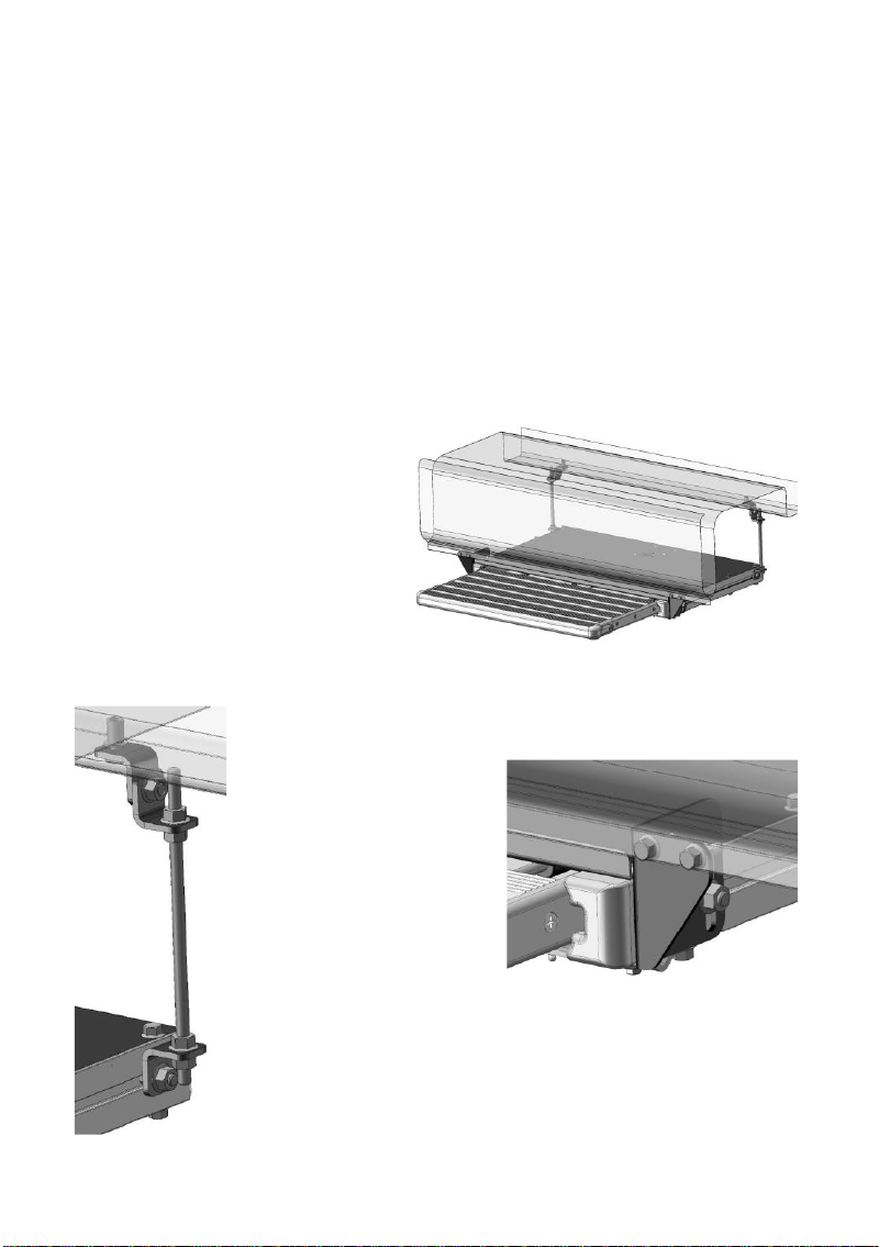
The picture shows the basic principles
for mounting the step.
Identify where the 4 front mounting bolts will go. The holes for this
fixation should be drilled in the lower flange of the outer chassis bar of
the vehicle. Drill the holes ø6.5
mm. Always protect all drilled
holes with zinc spray. Make
sure there is enough material in
the flange underthe hole. Place
the step with two bolts at the
flange and support it at the rear.
Take the flexible mounting
brackets supplied with the step.
These brackets can be
mounted in several ways. The
brackets should be used to fix
the rear side of the step to the bottom of the vehicle. It is recommended
that a sturdy section of the vehicle floor us used. Mount the brackets so
that they bridge the gap between step and vehicle floor / chassis. The
M8 studs should be placed as vertical as possible. This fixing requires
some technical knowledge and own interpretation.

6
Always try to go as vertically as possible straight up from
the fixing point on the rear of the step to the fixing points
on the vehicles floor.
Adjust the step so that it is horizontal under the vehicle.
Finally fit all bolts and nuts to complete the mounting of the
step.
You can adjust the height of the step under the vehicle by
adjusting the front brackets in the slot holes.
4.2 Mechanical adjustment
The step is being pushed out by two helical springs. The force at the springs can be adjusted
at a installed step under the vehicle.
There are two preload adjusters at the bottom plate of the step. To adjust the load, bring the
step in “out” position. Lose the two M8 bolts a little. Remove the two locking screws. Place a
6 mm hex key in the hex hole and adjust the load to plus or minus. After adjusting fix the
locking screws and M8 bolts. Both sides need to be in the same position after adjustment.
4.3 Electrical Installation
The step comes standard without cable loom, only with a simple close switch. A wiring loom
should be made according schedule in appendix 1.
Optional original cable loom including connector fuse and dashboard LED is available under
number S130 000 Ask your dealer for availability
Pls note that a safety Light at the dashboard in sight of the driver is strongly recommended
and in some countries legally required.
The connector used at the step is of the type AMP Super seal 2 pole male C 282080-1
The counter part is AMP SUPERSEAL 2 Way, 1 Row Female Connector Housing 282104-1
Remove
Remove
Lose a bit
Lose a bit

7
4.4 Using the Step:
You should test the step after installation. Follow these instructions:
1.MOUNTING –Check that all mounting bolts are in place and tightened.
2.MOUNTING –Bring the step out and apply a load : Max 150 Kg. Check if the mounting of
the step is correct for this weight. The construction of the step means that with a weight of
150 Kg the step will give slightly - this is normal !!
3.ELECTRICAL INSTALLATION –Check that the red LED on the dashboard turns red when
the step is out
If this small test procedure is successful, the step is ready to be used. If one of the tests fails
the problem should be resolved before putting the step in to use..
5Periodic maintenance / Inspection
5.1 Cleaning
The step must be cleaned in the normal cleaning schedule of the vehicle, depending on the
use of the vehicle and the type of the operation. Normal non-aggressive cleaning materials,
as used for cleaning the other parts of the vehicle, should be used.
The use of high-pressure water cleaners to clean the inside of the step is recommended.
Do not use aggressive solvents; these could affect the paint, and rubber as used on the step.
5.2 Periodic maintenance / Inspection
5.2.1 Small maintenance
The step has an open cassette. Dirt and other particles will ingress the step. So it will need
regular cleaning. It is recommended to spray some thin oil PTFE or silicone spray on the
wheels and locking mechanism and other moving parts on a regular basis.
We strongly recommend MOTIP PTFE spray at all parts in the step, do not use WD40 spray.
Other similar PTFE oil / grease sprays can also be used.
5.2.2 Yearly maintenance / Inspection
Major maintenance should be done once every six months or at every 30.000 cycles.
If the number of cycles per year is less than 10.000 the six monthly maintenance interval
Will still apply
Following the vehicle inspection schedule, check following points:
1. MOUNTING –Check if the all mounting bolts are in place and tightened.
2. MOUNTING –Bring the step out and test load Max 150 Kg. Check if the mounting of the
step is without deflection for this weight. The construction of the step is such that a weight
of 150 Kg will give a little deflection of the step. This is normal !!
3. ELECTRICAL INSTALLATION –Move the step out and check if the red LED on the
dashboard shines red when the step is out.
4. Check if the step move out completely. If needed adjust the preload at the springs
following 4.2

8
6Certification
Product description
Product AXS STEP
Mechanical Sliding step
Type AXS MD 600 SA / M
AXS MD 900 SA / M
Production under responsibility of
Company Acdeos BV
Address Touwbaan 1A
City 2352 CZ Leiderdorp
Country Netherlands
Website WWW.ACDEOS.COM
Legal represented by Mr. A de Moes
Conformity
Product is designed, tested and produced confirm:
The loading recommendations in the Machine directive 98/37/EG
step is tested for a maximum weight of 150 Kg
On behalf of producer:
Name / Function
A de Moes / Engineering
Date
10 December 2013
Place
Leiderdorp, Netherlands

9
7 Appendix 1; electric schedule

10
Appendix 2; Installation drawings:
AXS MD 600 M
430

11
AXS MD 900 M
430

12
ACDEOS BV
a Mobility Networks Company
Touwbaan 1A
2352 CZ Leiderdorp
The Netherlands
+31 71 5891819
www ACDEOS.com
This manual suits for next models
3
Table of contents
Other Acdeos Automobile Accessories manuals
Popular Automobile Accessories manuals by other brands

BURY
BURY CP 1100 Quick user guide

Cruz
Cruz 909-457 Assembly instructions

Carefree of Colorado
Carefree of Colorado 1628626972 quick start guide

TrailFX
TrailFX RLIK67 Assembly, Installation, Operation and Maintenance Instructions

SVC GROUP
SVC GROUP VTZ 001-497 manual

Code 3
Code 3 WingMan Installation & operation manual