Acdeos AXS FL User manual

Condensed Manual
A full size complete manual
is available on www.acdeos.com
ACDEOS BV
Touwbaan 1A
2352 CZ Leiderdorp
Netherlands
WWW.ACDEOS.COM
Date: March 2019
Rev. 2.3
AXS –FL Step

2
1Technical specifications
Product description Electrically operated step for mounting externally under the
vehicle floor
Installation Externally under the vehicle floor below the front, middle or rear
door
Dimensions Step depth 300 mm, Step width 600, 900 or 1000 mm depending
on model
Please refer to the installation drawings for detailed dimensions
Weight 25-32 Kg depending on the model
Load Maximum load 200 Kg (2000 N). This is always labelled on the
Step
Materials Frame; steel plate work, EP corrosion protected
Step: Aluminum profile and Plastic corner covers
Life cycle Tested life cycle of the step is 150.000 cycles
Electrical connection Waterproof 4 pin connector (IP65)
Drive Electric motor 12V 20W
Electric signals Electric signals are available via dashboard light: Step moving /
open
Safety functions Motor switched off by current control.
Cycle time Time required for opening or closing the step is approx 2,5 Sec
Legislation The product fulfils R107 UN Bus directive and 98/37 EC Machine
directive.

3
2Safety instructions
These Safety instructions should always be kept with the step. The
operator must be made aware of these instructions before operating
the Step. Read and follow these safety instructions carefully.
The step is intended to be an extra step to enter a vehicle. It should be used appropriately by
passengers to enter or exit a minibus, taxi camper or other vehicle, and the maximum load
should not be exceeded.
1. Before operating the step the vehicle must be stationary and the hand brake
or parking brake must be applied.
2. Before operating the step, ensure that there is nothing obstructing it. Look out
for people moving outside the vehicle near the step.
3. It is recommended that the step is only operated by the driver or other
qualified operators.
4. The driver or operator must have a clear view of the step when they are
operating it.
5. It is recommended that the middle of the platform is used when stepping onto
the step.
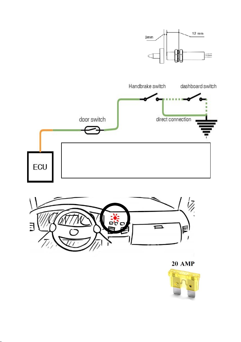
6. NEVER drive away when the RED dashboard LED light is still on, this means
that the step is not properly stowed.
7. The step platform must be kept clean and free of oil and other greasy
materials.
8. If there is any doubt about the safety of a passenger when using the step,
ensure they are assisted.
9. If you have any questions about the safe operation of the step, contact the
person responsible directly.
10. Never use the step for any other use than described here.
11. Never overload the step.
12. The step should always be operated until it is fully in or out.
13. Repair and maintenance must be done by qualified and trained staff only.
14. If any parts need replacing, ensure only original Acdeos Parts are used.
15. If the anti slip profile on the step becomes worn, the step platform must be
replaced.
16. Always use the recommended cleaning materials.
17. Report any unsafe aspects of the step to the step supplier.

4
3 Mounting / Installation
The installation can only be done by a company that is well known with bodybuilding or
modifying vehicles, which has the trained technical staff to do this job.
3.1 Mechanical Installation
For mounting the step you do not need to make any large vehicle adaptations. The step is
placed under the floor in the middle of the front, middle or rear door.
Chassis modifications are not needed.
Warning: Changing the vehicle chassis affects the strength of the vehicle. This kind of
changes is only allowed after approval of the vehicle builder / constructor. You need to
consult the vehicle builder for these kinds of changes. Acdeos cannot be made
responsible or held accountable for any vehicle / chassis changes.
Exact measurements of the product should be taken from the official installation drawings. Ask
Acdeos for the last revision and official installation drawing. Figures, drawings in this manual
are only for indication.
Installation:
Create a safe working condition. Lift the vehicle to the appropriate working height.
Define the place where you want to mount the step under the vehicle. Make sure the cassette
can be mounted on the required position without colliding with the chassis or other vehicle
parts. Make sure that the step is not to close to hot parts like the exhaust system. This
can damage the step.
The picture below gives the basic principles for mounting the step.
Define the place for the 4 mounting bolts on the front. The holes for this fixation should be
drilled in the lower flange of the outer chassis bar of the vehicle. Drill the holes ø6.5 mm.
Always protect all drilled holes with zinc spray. Make sure there is enough material in the
flange under the hole. Place the step with two bolts at the flange and support it at the rear.

5
You can adjust the height of the step
under the vehicle by adjusting the front
brackets in the slot holes.
Always try to go as vertically as possible
straight up from the fixing point on the rear
of the step to the fixing points on the
vehicles floor.
The M8 studs should be placed as vertical
as possible
Take the flexible mounting brackets supplied with the
step. These brackets can be mounted in several
ways. The brackets should be used to fix the rear
side of the step to the bottom of the vehicle. It is
recommended to find a strong point at the vehicle
floor. Mount the brackets in such a way that they
bridge the gap between step and vehicle floor /
chassis.

6
This fixing requires some technical
knowledge and own interpretation.
Adjust the step to be horizontal under the
vehicle.
Finally fit all bolts and nuts to mount the
step completely.
In the case the flange of the chassis
is too far back, it is possible to flip
the brackets as to place the step
further forward.
When the possibility of attachement on the back of the
step is too far back, or there is a fuel tank or something
similar in the way, it is possible to use a piece of L bar to
extend the back point of attachment.

7
3.2 Electrical Installation
Find a good route for the cable to the front of
the vehicle or to the area where it will be
connected to the vehicles electrical system.
The principal idea for the routing of the cable
loom is as follows: cable should run under the
vehicle to a place where you can enter the
vehicle. Try to find a dry place for the 4 pin
connector in the cable loom inside the vehicle
There are two possible operations of the
step.
1 - Door switch. Steps moves out
automatically when the door opens
2 - Driver operated switch on the dashboard
where the driver operates the step. In this
case, it is still recommended that the door
switch in installed. Without the door switch
the driver could forget to close the step when
the door is closed, and drive away with an
open step.
Connect the green wire at the handbrake
switch or other signal indicating that the
vehicle is stationary. You need a signal
when the vehicle is stationary. The
handbrake switch is not supplied with the
step.
For safety reasons we recommend this
signal is used.
If you decide not to use this
signal Acdeos cannot
take any responsibility
for any unsafe
operation of the step.
Cable colours:
black Ground
Red Power (Use a 20 Amp
fuse)
Green Ground signal for
operating the step

8
1. Close the door. Measure the gap between the door and the door post. Adjust the switch
so, when installed, there is 7 mm of space between the switch and the door or 3 mm
between switch and magnet.
2. Push the switch + plastic holder in the drilled hole and fix / seal with a bit of PU glue.
3. Place the magnet on the opposite position on the door. Fix the magnet with a screw.
12.5mm
Lead the cable with the door sensor through the
doorpost and stick the switch through the 12.5 mm hole
Place the Switch in the plastic holder. This is a tight fit.
You need to screw the holder around the switch.
Mechanical Installation of door switch: Find
the right place on the door to install the door
switch, preferably around the area in the
doorpost where you find the original door switch.
Make sure there is minimum around 10-12 mm
free space between the door and the door post
when the door is closed.
Drill a hole of 12.5 mm at the selected place.
The door switch is supplied as standard with the
cable loom.
Check that magnet does not touch the switch
when door is closed with high speed and force
(slammed)
Careful, the Magnet is brittle. First drill the hole
and then fix the magnet with the screw just tight
enough to fix it. Fixing it too hard will damage the
magnet.

9
4. When installing the switch using the nuts, the switch
must stick out at least 12 mm because of the need
for magnetic flow around the switch.
5. The distance between the end of the switch and the
door should still be 7 mm.
IMPORTANT: Max torque to fit the switch is 5 Nm (This is light hand tight) If you use
higher torque, the switch will break / crack, which will lead to unreliable door signals.
6. Place the red LED in the dashboard in the direct view of the driver. Connect the free wire
to 12 V power. The LED lights up red when the step is out and flashes when the step is
moving in or out.
7. Connect the black wire to ground.
8. Connect the red wire to 12V power. You need to add a fuse
of 20 Amp between the battery and the power cable. Decide
whether to connect the step to constant power or to power
behind the main switch. We recommend placing the step
behind the main switch. The step ECU has a sleep mode
using less than 1 mAmp in standby mode
9. Connect the cable loom to the step with the connector. Place
this connector preferably inside the vehicle in a dry area.
If you decide to use driver operation, place a switch on the
dashboard and connect it to the Green wire. Closed signal =>
step out. Open signal => step stowed. To prevent oversight from
the driver’s point, also install the door switch to prevent driving
with the step in outward position.

10
4Operation
4.1 Deploy Operation procedure
The step must have clearance from the vehicle. The
vehicle must have the parking brake on, and then
the step can be safely operated.
The electronics receive a signal from the door
switch or driver switch. If a door switch is installed
the step will move out automatically once the door
is opened.
Time for either the full deploy / out or the full stow /
in cycle is approximately 2.5 seconds. When the step is moving the red LED on the dashboard
will flash until the step is completely out.
If the step encounters an obstacle it automatically stops. It will move backwards for a few
centimeters and then move forward again. If there is still an obstacle it will repeat this
procedure three times, then it will stop in the position where it encountered the obstacle.
4.2 Stow operation procedure
To stow the step the door should be closed or the driver has to give a signal that the step
should stow. The same rules apply as for moving out.
Step out = Shining LED
Step moving = Blinking LED

11
At closing a signal from the close switch will indicate that the Step is completely closed. This
close signal will also give the vehicle the OK that it is safe to drive the vehicle away, the Red
LED light at the dashboard will go off. If the step is not stowed properly the RED LED keeps
blinking.
5Manual Operation
In case the step fails, it is possible to operate the step by hand. This is done by the following
procedure:
1. Put a large screw-driver through
the long hole in the bottom cover in the slot
in the motor base plate.
2. Twist the screwdriver
counterclockwise. This will unlock the
driving mechanism. Now the step can be
moved in or out by hand.
3. After moving the step in or out
return the screw-driver in the slot to re-lock
the step in the in or out position.
6Periodic maintenance / Inspection
6.1 Cleaning
To prevent severe damage to the step, the step must be cleaned thoroughly in the normal
cleaning schedule of the vehicle, depending on the use of the vehicle and the filthiness of the
operation. Therefore, especially in wintery situations when salt is being sprinkled on the road,
it should be cleaned more regularly. Normal non-aggressive cleaning materials, as used for
cleaning the other parts of the vehicle, should be used.
it is not recommended to use high-pressure water cleaners.
Do not use aggressive solvents; these could affect the paint, rubber and glue used on the step.
6.2 Periodic maintenance / Inspection
6.2.1 Small maintenance
This product is very low maintenance. This means that it is not necessary to grease any of the
moving parts on a monthly basis, apart from the yearly maintenance.
6.2.2 Regular inspection
Following the vehicle inspection schedule, check following points:
1. MOUNTING –Check that all the mounting bolts are in place and tightened.
2. MOUNTING –Bring the step out and have 2 people (Max 200kgs) step on it. Check
whether the mounting of the step is strong enough for this weight. The construction of the
step means that with a weight of 200 Kg the step will give slightly - this is normal !!
3. ELECTRICAL INSTALLATION –Move the step in and out electrically.
Check for unusual noises or uneven movement whilst the step is moving.
Check that the step stops automatically at the end of the stroke.
Step in = LED off

12
Check that the red LED on the dashboard turns red when the step is out.
Check that the buzzer works while the step is moving in or out. (If not disconnected)
4. SAFETY FUNCTION –Move the step out and try to stop it with your hand. The step should
stop, move back, and come out again. It will try this 3 times, then it will stop. It should go
back in after closing the door.
5. INTERLOCK VEHICLE –Release the vehicle handbrake, then try to operate the step. It
should not be possible to operate it. (unless the handbrake interlock is not installed)
6.2.3 Yearly maintenance / normal maintenance
A thorough maintenance check should be done once every year or at least every 10.000
cycles.
We recommend reduce the maintenance period to 6 months when the step is used in hard
conditions with much snow / ice / mud / gravel etc,
Normal maintenance:
Bring the step in the out position. Remove the bottom plate screws. Remove the bottom plate
by lifting it with a flat head screwdriver.
•Check all moving parts like, arm gears, push
rods and wheels for excessive play. If there is
excessive play on moving parts it is
recommended to replace these parts.
•Check the adjustment of the in and out switch.
•Check wires and electrical connections for
possible failures.
•Clean all parts
•Grease moving parts with MOTIP White
PTFE grease or normal bearing grease.
Close the bottom plate.
With step still in out position remove ty-rap at the rear of the
step from both rubber end caps.
Spray a good grease in the tube or use normal bearing
grease with a long brush. This is the most important part
of the maintenance.
Close rubber caps again and fit with a new Tie-wrap
We strongly recommend MOTIP White PTFE grease part
nr 090204 for all parts in the step, do not use WD40 or
silicon sprays
Other similar PTFE grease sprays can also be used.
This spray is also available at Acdeos under part number
S150 310

13
7Certification
Product description
Product AXS STEP
Electrical Sliding step
Type AXS FL 600 A
AXS FL 900 A
AXS FL 1000 A
Production under responsibility of
Company Acdeos BV
Address Touwbaan 1A
City 2352 CZ Leiderdorp
Country Netherlands
Website WWW.ACDEOS.COM
Legal represented by Mr. A de Moes
Conformity
Product is designed, tested and produced confirm:
The loading recommendations in the Machine directive 98/37/EG
step is tested for a maximum weight of 200 Kg
On behalf of producer:
Name / Function
A de Moes / Engineering
Date
05 August 2015
Place
Leiderdorp, Netherlands

14
8Appendix 1; electric schedule

15
9Appendix 2; Installation drawings:
AXS FL 600 / 900 / 1000 A

16
ACDEOS BV
A Mobility Networks company
Touwbaan 1A
2352 CZ Leiderdorp
The Netherlands
+31 71 5891819
www ACDEOS.com
Other manuals for AXS FL
2
Table of contents
Other Acdeos Automobile Accessories manuals