Acdeos AXS FL User manual

AXS –Ramp Manual
Manual
Acdeos BV
Touwbaan 1A
2352 CZ Leiderdorp
Netherlands
www.ACDEOS.com
Date: 3-4-2020
Doc AR9000 04
Rev. 2
AXS –FL Ramp

AXS –Ramp Manual
AXS FL RAMP Manual rev 1 1
Index
1Technical specifications.................................................................................................1
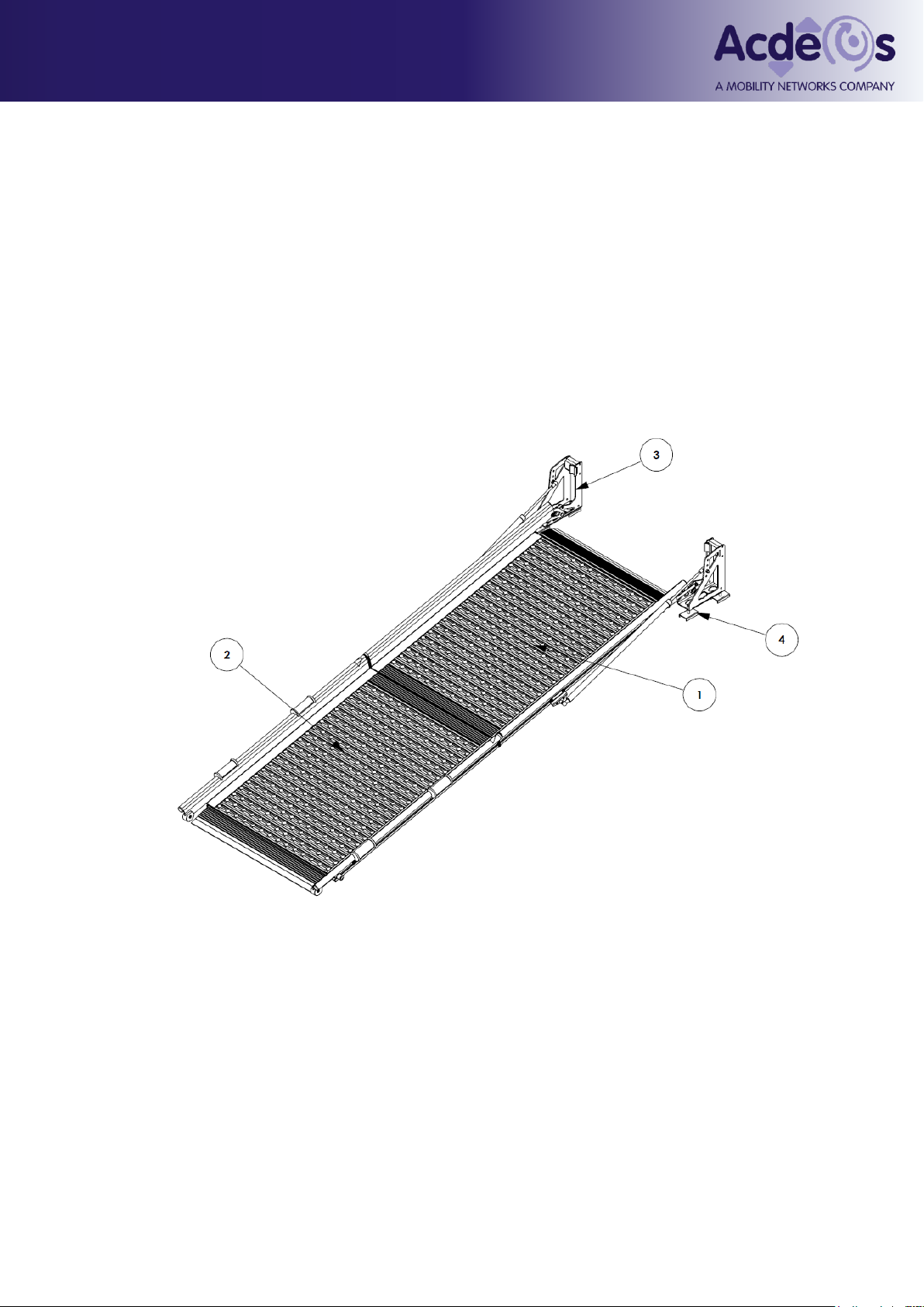
2Nomenclature ....................................................................................................................2
3Safety instructions...........................................................................................................3
4Constraints.........................................................................................................................4
4.1 Legal requirements: ............................................................................................................................... 4
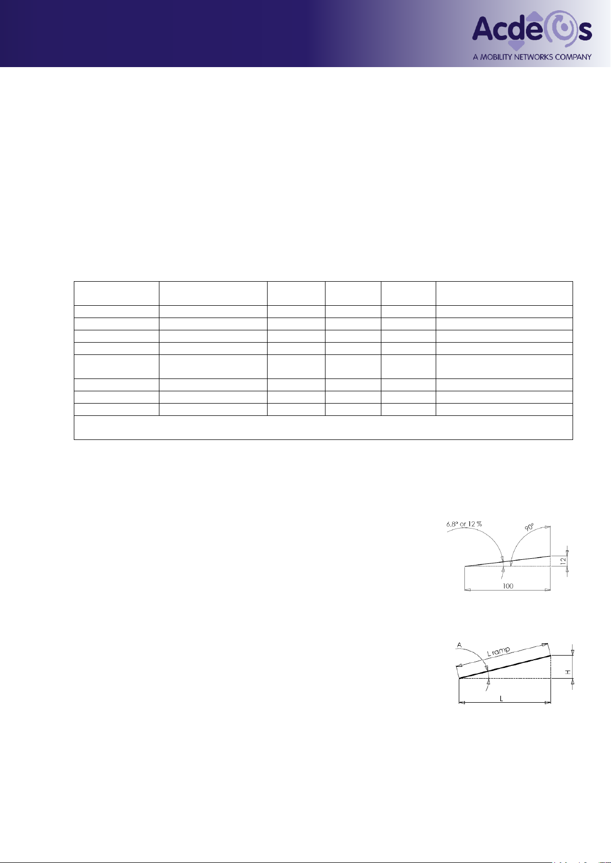
4.2 Slope in % and Deg. .............................................................................................................................. 4
5Operation............................................................................................................................5
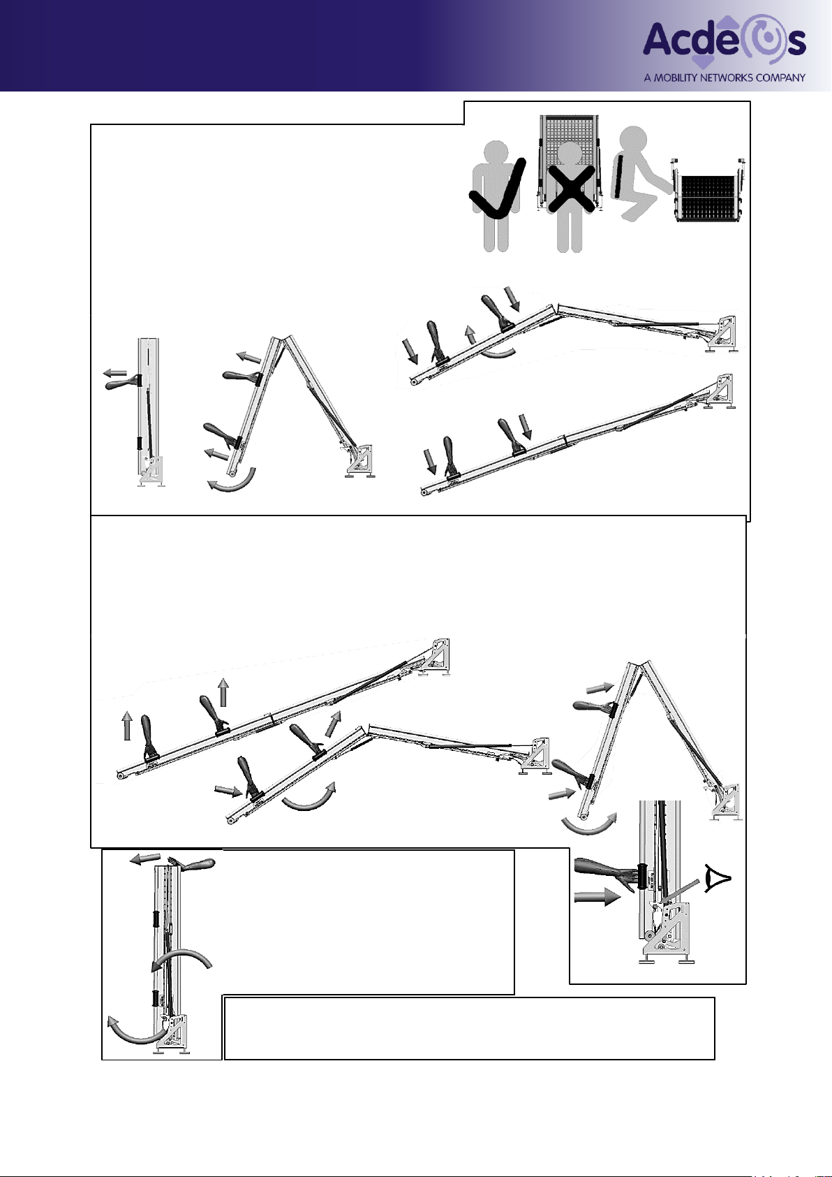
5.1 Deploy Operation procedure ramps with auto lock ................................................................................ 5
5.2 Close operation procedure ramps with auto lock .............................................................................. 5
5.3 Emergency operation procedure ramps with auto lock .................................................................... 5
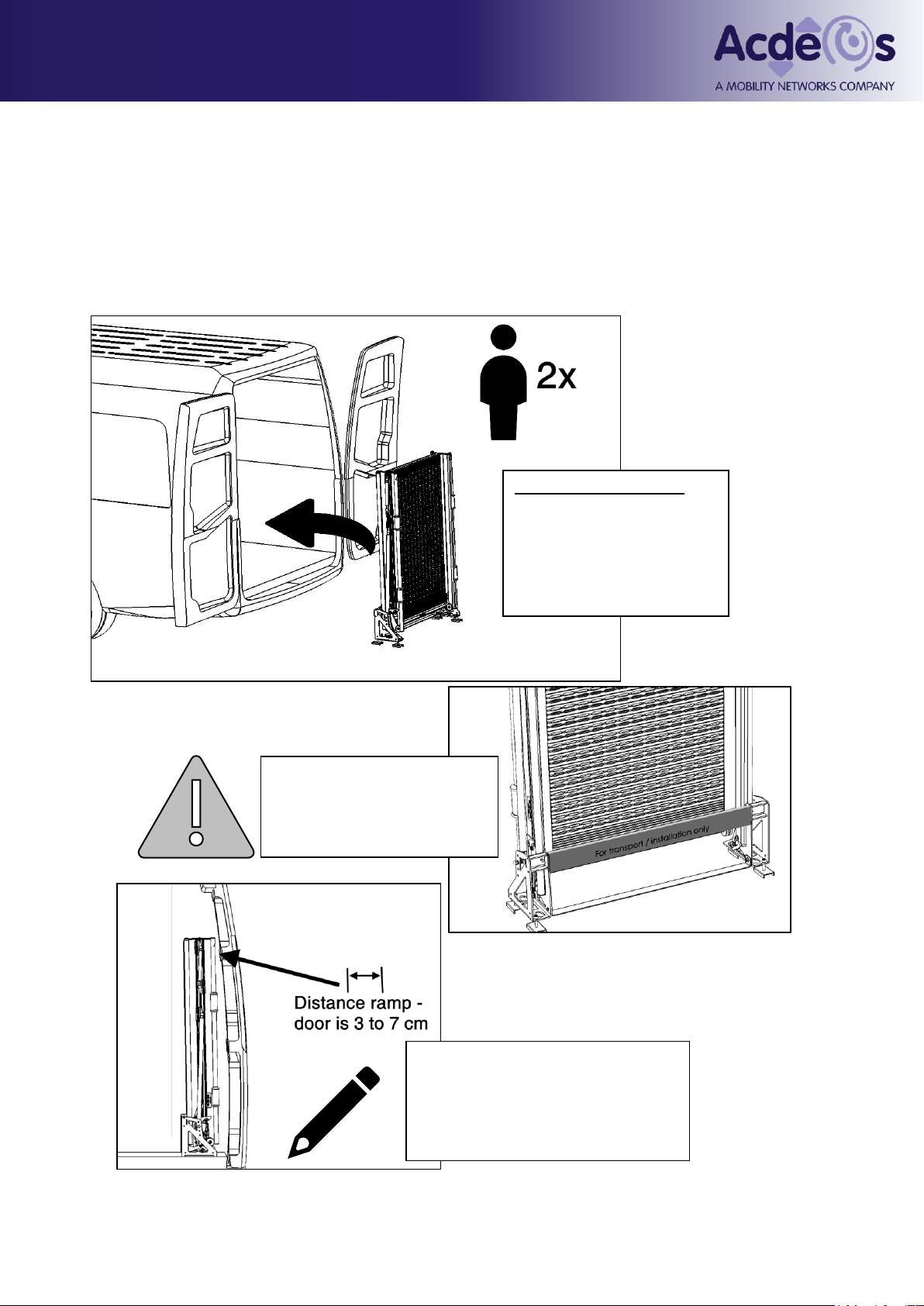
6Mounting / Installation ....................................................................................................6
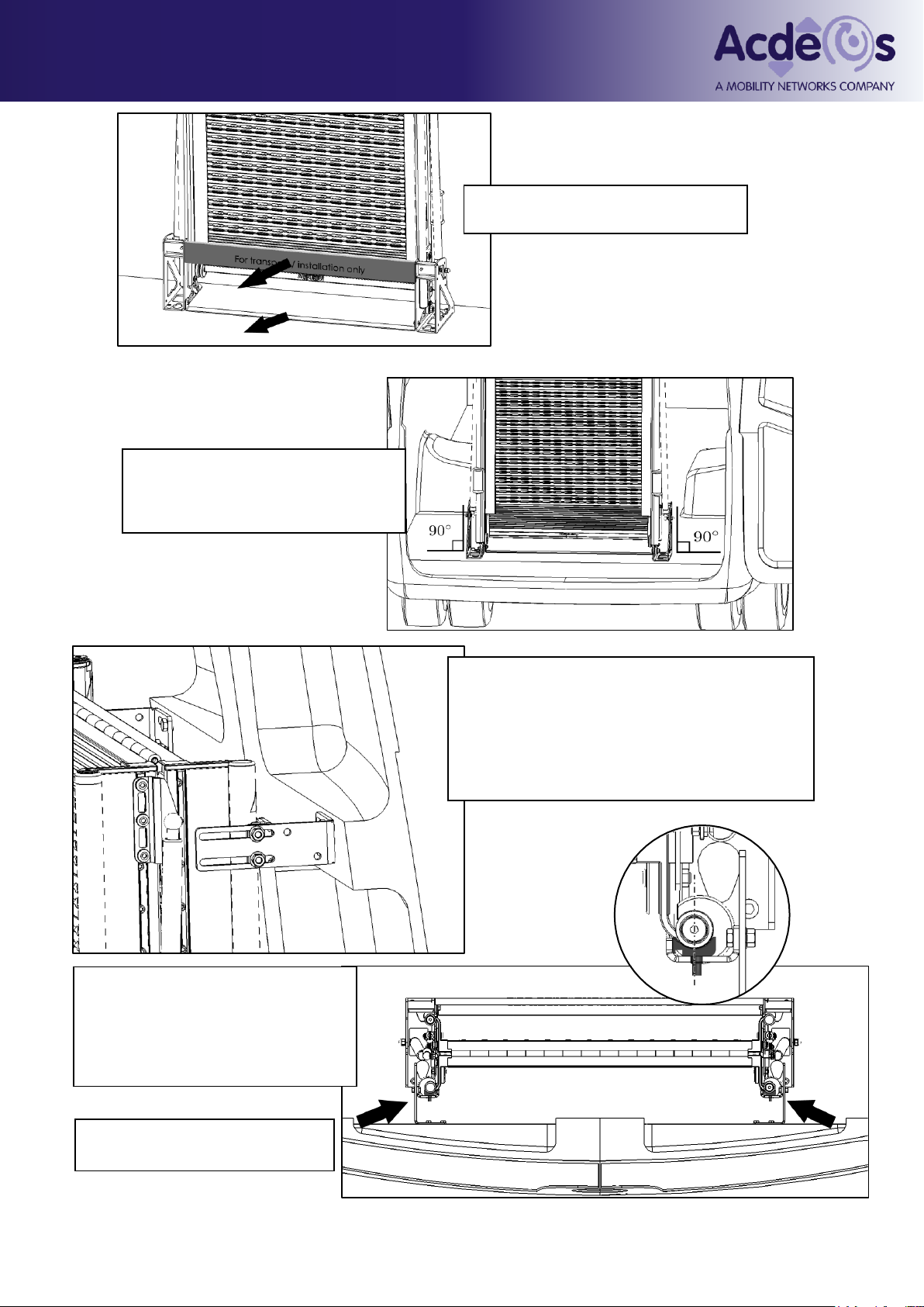
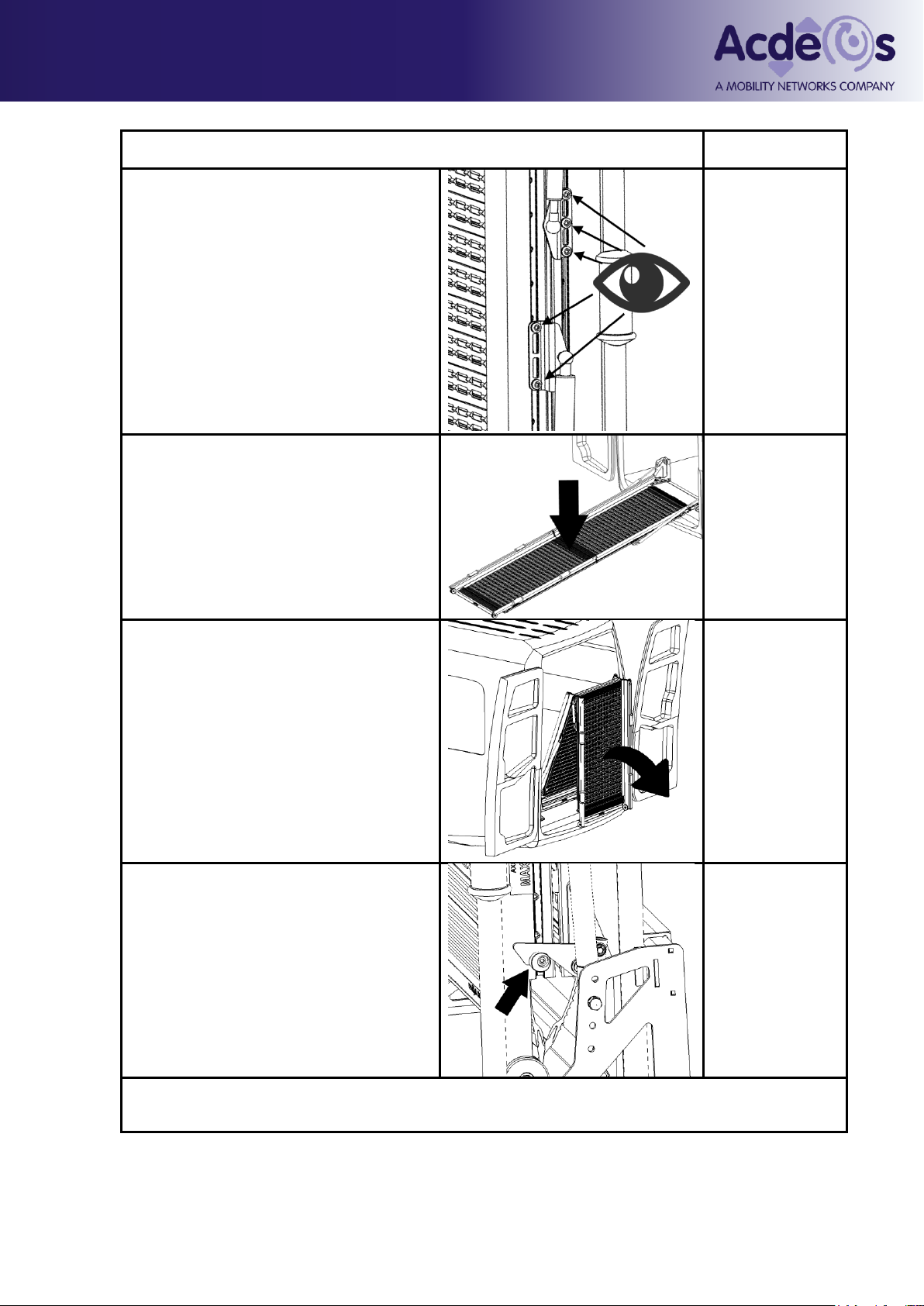
6.1 Mechanical Installation .......................................................................................................................... 6
Place brackets left and right ............................................................................................................................. 8
The black nylon roll is eccentrically and can be adjusted if the ramp lock is to loose. ............................ 9
7Maintenance.....................................................................................................................24
7.1 Cleaning ................................................................................................................................................ 24
7.2 Periodical maintenance....................................................................................................................... 24
7.3 Yearly inspection .................................................................................................................................. 24
8Repair ................................................................................................................................25
8.1 Replacement of Gas springs .............................................................................................................. 25
8.2Adjustment of the auto lock ................................................................................................................ 27
8.3 Adjustment of the platform.................................................................................................................. 29
9Spare parts.......................................................................................................................30
10 Additional kits..............................................................................................................32
11 Environment .................................................................................................................32
12 CE Certification............................................................................................................33
13 M1 Certification............................................................................................................34
Appendix I; Installation drawing Double ramps:..........................................................36
Appendix II: Drill tool ...........................................................................................................37
1Technical specifications
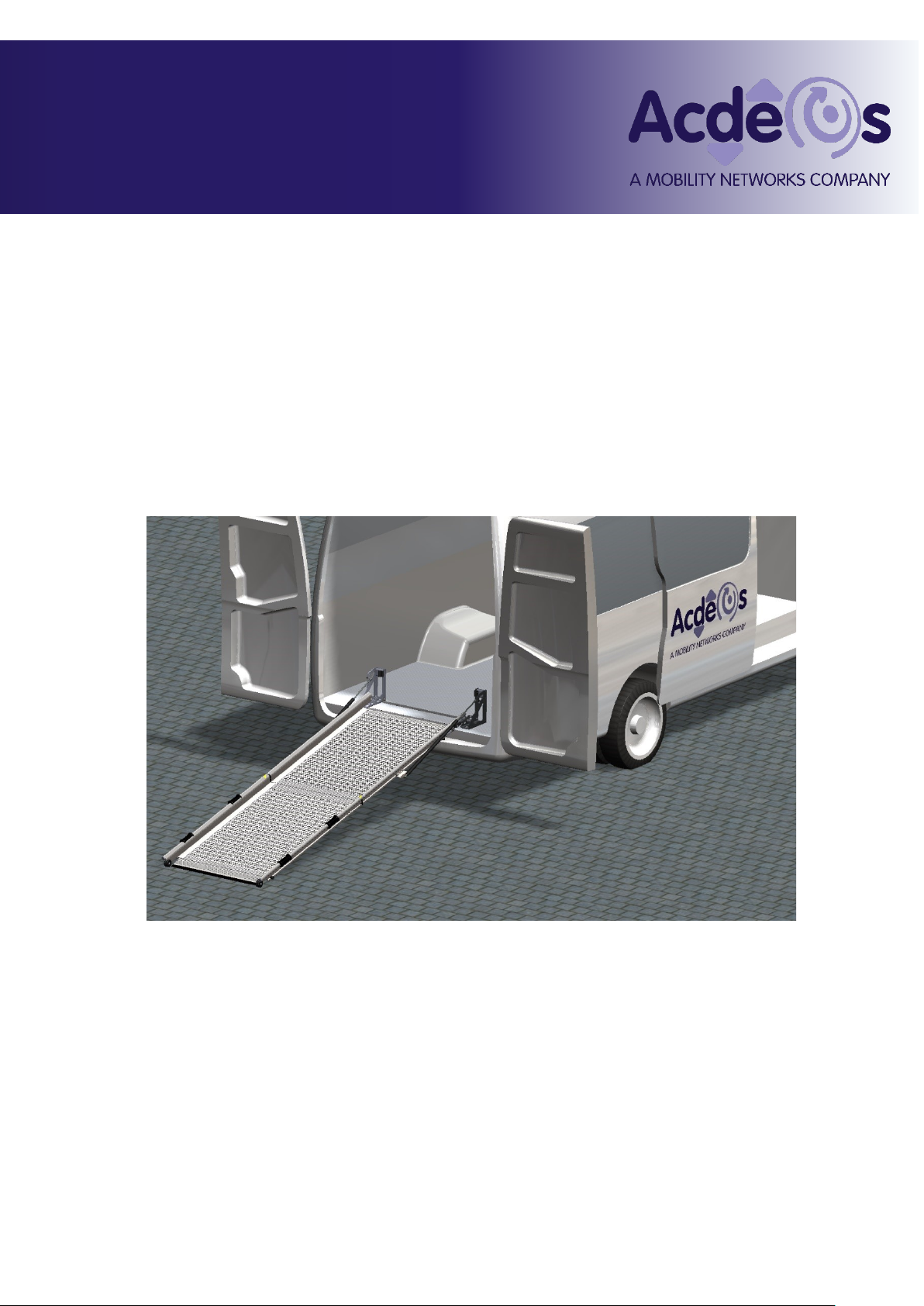
Product description Manual operated wheelchair ramp for vans and mini buses.
Installation On the vehicle Floor at the middle or rear door
Dimensions Ramp length 2100, 2500, 2800 mm
For detailed dimensions please refer to the installation drawings
Weight AXS AR FL 210-8/2 39 Kg
AXS AR FL 250-8/2 45 Kg
AXS AR FL 280-8/2 48 Kg
AXS AR FL 280-10/2 52 Kg
Load Maximum load 400 Kg (4000 N) This is always labeled on the Ramp.
Materials Ramp; Anodized Aluminium structure with Aluminium profile anti-slip platform.
Integrated Aluminium hinge. Mounting points: steel.
Legislation The product complies with the 2006/42/EC and NEN-EN 1756-1

AXS –Ramp Manual
AXS FL RAMP Manual rev 1 2
2Nomenclature
The type of the ramp has to be understood as follows:
AR FL-XXX/Y Z where:
AR = AXS Ramp
FL = FL series of products
XXX = Length of platform in Centimeters (210, 250 or 280)
Y = Width 8 = 86 cm / 10 = 97 cm
Z = Number of platforms (2 or 3)
Meaning a AR FL 210-8/2 is a AXS ramp of the FL series with a 2,1 meter length, 0,86 meter width in
two parts (platforms).
Components of the double ramps
1. first platform
2. second platform
3. feet assembly
4. fixation kit

AXS –Ramp Manual
AXS FL RAMP Manual rev 1 3
3Safety instructions
These Safety instructions should always be with the ramp. The operator has to
be made aware of these instructions before operating the ramp. Read these
safety instructions carefully and act on them.
The ramp is constructed as a boarding device for passengers in a wheelchair. It should be used
accordingly by passengers and assisting persons, as long as they are not heavier than the maximum
load, to enter or exit a minibus, van, taxi or other vehicle.
1. Before you can operate the ramp the Vehicle must be stopped and the hand or park brake
applied.
2. Make sure it is safe to load or unload your passengers.
3. Before operating the ramp, make sure that there neither anyone nor any obstacle at or
near to the ramp. Also ensure that there is neither anyone nor any obstacle outside the
vehicle or in the path of the ramp when in motion.
4. It is recommended that the ramp is operated by the driver only or other qualified
operators.
5. The driver or operator must have a clear view of the ramp when maneuvering the ramp.
6. Wheelchair passengers should always be assisted while boarding or un-boarding the
vehicle.
7. The ramp platform must be kept clean and free of oil and other slippery materials.
8. If you have any questions about the safe operation of the ramp, contact the person
responsible immediately.
9. Never use the ramp for any other use than as described above.
10. Never overload the ramp.
11. The ramp should be used when it is completely unfolded and firm on the ground.
12. Repair and maintenance must to be carried out by qualified and trained staff only.
13. In case of exchanged parts –only the original parts of the ramp must be used.
14. Always use the recommended cleaning materials.
15. Report any unsafe conditions of the ramp or problems during operation to the ramp
supplier.

AXS –Ramp Manual
AXS FL RAMP Manual rev 1 4
4Constraints
The AXS Ramp has been designed to be functional and reliable. The product is made as simple and
reliable as possible. The possibility of use during severe environmental conditions has been taken into
consideration for the design of the ramp.
The double ramp is made without supporting legs. This is the only way to ensure having a straight
platform under any loading condition.
4.1 Legal requirements:
The legal requirements in and outside Europe are different for each region / country.
There is a common bus directive 2001/85 EC in Europe (as previously mentioned the product complies
with this directive) also used by Norway; however this is only applicable for M2 and M3 vehicles. In
addition to this many countries do have their local requirements.
Also many applications of the AXS ramp will be found in vehicles under M1 legislation. There are no
European guidelines for ramps in these vehicles.
Two important aspects in all the different legislations are the platform width and the slope of the ramp.
The table below gives a guideline for the different known legislations.
Country
Legislation /
guideline
Max
slope
Minimum
width
Max
Load
Other requirements
Denmark
none
Finland
InvaTaxies
8 %
France
25%
800 mm
300 Kg
height side edge 50 mm
Germany
DIN 75078-1
Netherlands
Permanente taxi
regeling
20%
800 mm
300 Kg
height side edge30 mm
Sweden
M1 wheelchair bus
15%
United Kingdom
DPTAC
12%
800 mm
300 Kg
EU
2001/85 EC
12% 1
800 mm
300 Kg
Only M2 and M3
Notes
1) measured from a curbstone of 150 mm
ACDEOS recommends a maximum slope of 25 % when the wheelchair passenger has assistance from
trained staff.
If the person has to enter the vehicle by himself the maximum slope should be 12 %.
4.2 Slope in % and Deg.
Often % slope and Deg are mixed-up. Below you find the explanation of a
slope in ° (Deg) and %.
An angel is divided in degrees or °. A straight angel is 90° a full circle is 360°
Example: For a ramp according to EC bus directive the maximum angle is 6,8°
Another way to measure an angle is the % of the slope. If you move 100 cm
forward and in that 100 cm raise 12 cm the percentage of that slope is 12%
How to calculate:
If you want to know the slope A in % from a ramp
The % slope of a ramp is: A = H / L * 100%.
Normally you don’t know L you only know L ramp. For relative small slopes you
can say L ramp = L. This is not exact right but normally good enough. So than the
formula is: A = H / L ramp * 100%
For calculating the angel A in deg you need a calculator with sin, cos and tan.
Calculate H / L ramp than take the inv (inverse) tan of this value and you have the
angel of the ramp. Again this is not exact right but for small angels good enough.
So the formula is: A = inv tan (H / L ramp )

AXS –Ramp Manual
AXS FL RAMP Manual rev 1 5
5Operation
5.1 Deploy Operation
procedure ramps with
auto lock
To open the ramp, first grab the highest handle and pull
out. The auto lock system will unlock the ramp
automatically. When the ramp is coming out, place the
second hand at the second handle and guide the ramp
to the ground. The ramp is supported by gas springs.
Gently handle the ramp and let the gas springs do their
job to support the movement.
5.3
Emergency operation
procedure ramps with auto
lock
To open the ramp from inside, first
open de doors than firmly push the
ramp at the top. It will go out and
open automatically.
5.2 Close operation procedure ramps with auto lock
Grap the ramp with two hands at both handles at one side. Lift the platform and at the same time let it
bend in the natural way. Do not try to bend it aginast the force of the middle gas spring. Close the
ramp further by pushing it in. When the second platform is standing vertical, let the first platfom loose
and let it go. It will drop close and close automaticaly.
Do NOT use the emergency operation as the standard way
to open the ramp, this will cause damage to the ramp!

AXS –Ramp Manual
AXS FL RAMP Manual rev 1 6
6Mounting / Installation
The installation can only be carried out by a company familiar with building or modifying vehicles and
which has the staff qualified for such work.
6.1 Mechanical Installation
The fitting of the ramp does not involve major vehicle adaptations. The ramp is mounted on top of the
floor in the middle or rear door. No modification of the chassis is needed. Exact measurements of the
product should be taken from official installation drawings. Ask Acdeos for the final revision and official
installation drawing. The figures and drawings used in this manual are for indication only.
Mechanical Installation
Always create a safe working
environment. As the weight of
the ramp exceeds 25Kg; it is
advisable for two people to
be needed for lifting the ramp
in or out the vehicle.
Do not remove the wooden
and steel transportation
distance pieces between the
feet assemblies until the ramp
is fitted into the vehicle.
Locate the exact position where the
ramp will be fitted at the floor. The
ramp should be placed as close as
possible to the door, leaving 3-7cm
clearance space when the door is
closed.

AXS –Ramp Manual
AXS FL RAMP Manual rev 1 7
Mark out the position for the 4x M10
mounting bolts. Drill the 4 (Ø10.5mm)
holes through the floor in a
rectangular pattern of 1004mm x
210mm.
Warning: Do not copy the hole
pattern from the ramp as the holes
in the feet assembly are in a
random position when the ramp is
loose from the floor.
Check under the vehicle for the
position of the chassis. In some
applications the reinforcing U-profiles
may not fit properly, in such cases the
U-profile will need to be modified to
make it fit.
If a new back-up plate is required
please use one with a similar surface
area of 35 cm2 to fit the
requirements.
Place the ramp in the vehicle and fix using
the M10 bolts. If the holes are going
through the chassis, longer bolts may be
needed. These bolts can be purchased
from a local supplier. Bolts used must be
to DIN 912 / ISO 4762 specification M10 x
length (as regulated) –10.8.

AXS –Ramp Manual
AXS FL RAMP Manual rev 1 8
Finally remove the wooden and steel
transportation distance pieces.
Check if the Feet assembly is
standing strait under 90 with the floor.
If not tighten or loose the M10
fixations bolts
Ramp stop / Ramp Anti rattling device.
You will also need to install the ramp stop at the
door to prevent the ramp for rattling or hitting
against the rear door/window. `
We recommend positioning this as high as
possible at the door
The bracket needs to be fitted with the
two rivet nuts M8. (Drill Ø11 mm
holes).
Position the bracket so that the rubber
aligns with the rail of the ramp.
Place brackets left and right
Adjust the brackets so the ramp is
held tight when the door is closed.

AXS –Ramp Manual
AXS FL RAMP Manual rev 1 9
Before using the ramp: The ramp should always be tested after installation.
Follow the following instructions
checked
MOUNTING –Check that all bolts on the
ramp are in place and tightened. Check that
the MAX load stickers are on the ramp
MOUNTING –Unfold the ramp and load it
with the max load as indicated at the ramp
or approx 4-5 people. Check that the fixing &
fitting of the ramp is strong enough for this
weight.
OPERATION –Move the ramp in and out to
check that all moving parts are running
freely.
Check that the ramp closes properly into the
auto lock
The black nylon roll is eccentrically and
can be adjusted if the ramp lock is to
loose. See 8.2
A loose lock will give a rattling noise.
If this small test procedure is followed with success the ramp is ready to be used. If one of the steps is
failed please resolve the problem before putting the ramp in to service use.

AXS –Ramp Manual
AXS FL RAMP Manual rev 1 10
7Installation of options
7.1 600 Kg leg kit
This installation should be done at an
installed ramp in the car.
It is possible at ramps in stock but you
need to unfold the ramp.
Needed tools:
Allen key 6 mm + 3 mm
Warning: Always check the position of the T
nuts after fitting. They must be at an straight
angle with the slot in the Alu profile
Needed parts
Leg kit AR 200 073
Unfold the ramp.
Remove the centre gas spring including the
ball joint from the bracket on platform 1 by
unscrewing the M8 nut holding the ball joint in
place.
Remove the mounting bracket and leave the t
Nuts in the slot from the side profile.
- mount the bracket of the leg using the T nuts
of the previous bracket following beside
picture.
- Make sure it is mounted as far to the plastic
end cap as possible.
- Tighten the bolts M8 (30 Nm)
- check the position of the T nuts

AXS –Ramp Manual
AXS FL RAMP Manual rev 1 11
- Mount the leg hinge part at the second
platform, as far to the plastic end cap as
possible.
- Make sure the lip falls in slot.
- Tighten the bolts M8. (30 Nm)
- check the position of the T nuts
Flip over the gas spring mounting bracket, so
the ball is facing up instead of down.
Do not tighten the bolts entirely so the bracket
can still slide in the slot.
Mount the gas spring to the bracket of the leg
and move the other bracket to the furthest
extend and tighten the bolts
Mounting the right leg
Mount the turning point of the push rod at
platform 1 as far to the plastic end cap as
possible.
Mount the turning point of the leg as close to
the plastic end cap as possible, make sure the
lip falls in the slot before tightening the M8
bolts
- check the position of the T nuts
Place the holding blocks for the legs in such a
way they hug the legs when the ramp is
closed.
Adjust the length of the leg on both sides by
turning in or out the leg feet.
At a flat ground, with the ramp unfolded from
the vehicle, the legs should be approx. 1 cm
free from the floor.
Fix the legs with the set screw.
And you are ready
1 cm free

AXS –Ramp Manual
AXS FL RAMP Manual rev 1 12
7.1.1 Bump stop
Needed tools: size 13 wrench, allen key size 5
Remove the m8 nut from the gas spring.
Do not remove the gas spring from
the hole.
Place the bump stop assembly on the feet.
Open the ramp

AXS –Ramp Manual
AXS FL RAMP Manual rev 1 13
Place the bracket with loosely fixed bolts in the
side profile.
Close the ramp and adjust the bracket so the
rubber bump stops aligns with counterpart
Check the t-nuts for being fit properly square
on the slot
Tighten all nuts and bolts to 30 Nm
30 Nm
Repeat on other side

AXS –Ramp Manual
AXS FL RAMP Manual rev 1 14
7.2 Quick lock
Mechanical Installation
Always create a safe working
environment. As the weight of
the ramp exceeds 25Kg; it is
advisable for two people to be
needed for lifting the ramp in or
out the vehicle.
Do not remove the wooden
and steel transportation
distance pieces between the
feet assemblies until the ramp
is fitted into the vehicle.
Locate the exact position where the
ramp will be fitted at the floor. The
ramp should be placed as close as
possible to the door, leaving 3-7cm
clearance space when the door is
closed.
Mark out the position for the 4x M10
mounting bolts for the Mounting plates. Drill
the 4 (Ø10.5mm) holes through the floor in a
rectangular pattern of 956mm x 155 mm this
is a different pattern as for fixed installation

AXS –Ramp Manual
AXS FL RAMP Manual rev 1 15
Warning: Do not copy the hole pattern from the ramp
as the holes in the feet assembly are in a random
position when the ramp is loose from the floor.
Check under the vehicle for the position of the chassis. In
some applications the reinforcing U-profiles may not fit
properly, in such cases the U-profile will need to be
modified to make it fit.
If a new back-up plate is required please use one with a
similar surface area of 35 cm2 to fit the requirements.
Place the two mounting plates with the mushrooms in
the vehicle and fix using the M10 bolts. If the holes
are going through the chassis, longer bolts may be
needed. These bolts can be purchased from a local
supplier. Bolts used must be to DIN 912 / ISO 4762
specification M10 x length (as req’d) – 10.8
Place the distance bar between the
two feet assemblies
Fit the toggle device at the left and right
feet. Carle full there is a left and right
device. Fix with the two M8 screws together
with the distance bar.

AXS –Ramp Manual
AXS FL RAMP Manual rev 1 16
Finally remove the wooden
transportation distance piece.
Check if the Feet assembly is
standing strait under 90 with the floor.
If not tighten or loose the M10
fixations bolts
Ramp stop / Ramp Anti rattling device.
You will also need to install the ramp stop at the door to prevent
the ramp for rattling or hitting against the rear door/window.
We recommend positioning this as high as possible at the door
The bracket needs to be fitted with the
two rivet nuts M8. (Drill Ø11 mm
holes).
Position the bracket so that the rubber
aligns with the rail of the ramp.
Place brackets left and right
Adjust the brackets so the ramp is
held tight when the door is closed.
Place the ramp in the vehicle and slide
over the mushrooms / mounting plate with
the slot holes.
Lock with the toggle device and adjust the
toggle if needed to get a tight fit to prevent
the ramp from rattling.

AXS –Ramp Manual
AXS FL RAMP Manual rev 1 17
Before using the ramp: The ramp should always be tested after installation.
Follow the following instructions
checked
MOUNTING –Check that all bolts on the
ramp are in place and tightened. Check that
the MAX load stickers are on the ramp
MOUNTING –Unfold the ramp and load it
with the max load as indicated at the ramp
or approx 4-5 people. Check that the fixing &
fitting of the ramp is strong enough for this
weight.
OPERATION –Move the ramp in and out to
check that all moving parts are running
freely.
Check that the ramp closes properly into the
auto lock
The black nylon roll is eccentrically and can
be adjusted if the ramp lock is to loose. See
8.2
A loose lock will give a rattling noise.
If this small test procedure is followed with success the ramp is ready to be used. If one of the steps is
failed please resolve the problem before putting the ramp in to service use.

AXS –Ramp Manual
AXS FL RAMP Manual rev 1 18
7.3 Turning device
Mechanical Installation
Always create a safe working environment. As the
weight of the ramp exceeds 25Kg; it is advisable for
two people to be needed for lifting the ramp in or out
the vehicle.
Do not remove the wooden
and steel transportation
distance pieces between the
feet assemblies until the ramp
is fitted into the vehicle.
Assemble the lock and the centre piece in the
bottom plate assembly.
You can choose the direction of the locking lever
pointing side or rear
Use blue Loctite on the M6 wire from the center piece to
prevent it from loosening
Same for Left or right version
First assemble the turning device.
Place the pole at the bottom plate and fix with the 3 bolts (M10)
Same for Left or right version
Fix the upper fixation bracket to the pole
Same for Left or right version
Do not put the ramp on the turning device yet.
First position the turning device in the vehicle.

AXS –Ramp Manual
AXS FL RAMP Manual rev 1 19
Locate the exact position where
the ramp will be fitted at the floor.
The ramp should be placed as
close as possible to the door,
leaving 3-7cm clearance space
when the door is closed.
When the ramp must have a swing in stow
position:
Position the turning device in such a way that it
can turn inside but does not collide with the wheel
arch.
This only applies when the ramp must be able to
be turned to an inside stow position
See below sketch with approximately dimensions
In case the ramp should only be able to
swing out, you should position the swing
unit in such a way that it stays clear from the
door post in the swing out position
Important note:
Ensure that the ramp will stay free from the door
post if the door post curves in at the top of the
door. As you have not fitted the ramp at the
turning device yet, you should pull down a line
from the imaginary highest point of the ramp
projected at the doorpost down to the turning
device.
Other manuals for AXS FL
2
This manual suits for next models
4
Table of contents
Other Acdeos Automobile Accessories manuals
Popular Automobile Accessories manuals by other brands

Silvercrest
Silvercrest SBTF 10 C2 operating instructions

Purpleline
Purpleline Quattro Titanium Installation guide and user information

UNEEK
UNEEK GQ-FB-C-ASMO Fitting instructions

Vanguard
Vanguard VG300S Fitting instructions

CARFACE
CARFACE DO CFRBC001F instructions

Horn Tools
Horn Tools HTOHIRSA01 Mounting instructions