ACE LEDS Pencil AC30CD700APT7L User manual

Output
Power
Input
Power
Input
Current
Min PF
(full load)
Max THD
(full load)
Output
Voltage
Output
Current
T Case
Max
Min
Starting
Temp
IP
Rating
Efciency
Up To
Dimming
Protocol
Dimming
Range
30 W 36 W 0.29 A @ 120 V
0.13 A @ 277 V >0.95 <20% 9-42 V 125-700 mA, *±5%
*If Vf < 24 V,
±7%
90˚C -35˚C
64 83% 0 to 10 V 0.5-100%
to off
PRIMARY SPECIFICATIONS:
AC30CD700APT7L PencilTM Programmable LED Driver
Input Voltage 120-277 Vac, 50/60 Hz
Output Power 30 W (max)
WIRING:
Lead Lengths
Black 5.9" Blue 5.9” Purple 5.9”
White 5.9” Red 5.9” Pink 5.9”
PHYSICAL:
Dimensions Length Width Height
AC30CD700APT7L 5.5" 0.75” 0.75"
WHITE
LED
DRIVER
V-
INSTALLATION:
• IP64
• Mounting: 5.1”
• LED driver cases should be grounded
• LED drivers shall be installed inside electrical enclosures
• Use 18 AWG 600 V, 105
˚C tinned stranded copper wires
• Max ambient temp if mounted on metal surface to achieve
50,000 hour lifetime (case @ 75 °C) : 62 °C.
• Max ambient temp if not mounted on metal surface to achieve
50,000 hour lifetime (case @ 75 °C) : 51 °C.
WARRANTY:
• 5 Year Limited Warranty, 3 Years @ T case max
90˚C
APPROVALS:
• UL 8750
• EMC: EN55015, EN61000-4-2,3,4,5,6,8,11
• EN61000-3-2 Class C
• Class P listed
SAFETY, RATINGS AND PROTECTION:
• UL and CUL recognized
• Class 2 output
• Over current protection: 95-108%
• Open circuit and short circuit protection
• Working ambient temperature range: -35-70°C
• Working relative humidity: 10-100%
• Storage temperature: -40-85°C
• Storage relative humidity: 5-100%
• Damp location: Use only within an enclosure
• Inrush current: 35 A @ 277 Vac cold start
± 25˚C
• MTBF: >200 khrs to MIL-HDBK-217 @ 25˚C, GB
• Vibration: 10-500 Hz, 5G 12 min./lcycle, period for 72 minutes each
along X, Y, and Z axis
LISTED
E332747
RoHS
COMPLIANT
LEAD-FREE
LISTED
E332747
©2022 5July2022 Data is based upon tests performed by AC Electronics in a controlled environment and representative performance. Actual performance can vary
depending on operating conditions. Specications are subject to change without notice. All specications are nominal unless otherwise noted.
For questions or to place an order contact us at oemsales@aceleds.com or 800-375-6355
or your local WPG American Sales representative at inquiry@wpgamericas.com or 888-WPG8881

AC30CD700APT7L PencilTM Programmable LED Driver
©2022 5July2022 Data is based upon tests performed by AC Electronics in a controlled environment and representative performance. Actual performance can vary
depending on operating conditions. Specications are subject to change without notice. All specications are nominal unless otherwise noted.
For questions or to place an order contact us at oemsales@aceleds.com or 800-375-6355
or your local WPG American Sales representative at inquiry@wpgamericas.com or 888-WPG8881
NFC PROGRAMMER
INSTUCTION MANUAL
QUICK REFERENCE GUIDE:
1. In the
“Conguration”
Screen you can
choose your driver
type and driver
settings using the
blue arrow keys and
green ‘OK’ button.
2. Once nished,
tap the red
“Back” button to
return to the
“Summary” screen.
3. Place the NFC
Programmer directly
on top of the NFC area
of the driver and press
the green “OK” button.
If successful, the
device will beep once
and will display a red
“PASS”. Otherwise,
it will beep 3 times
and display a red
“FAIL”.
How to Program Driver:
NFC Area
How to Read Driver:
1. Use the red “Back” button to
switch back and forth between
the “Summary” and
“Conguration” screens.
2. Place the NFC Programmer directly
on top of the NFC area and press
the blue “Up” arrow. The device will
beep once and display a summary
of the currently programmed
settings.
NOTE!: You might also see a red “Mismatched!” message, which indicates that the current program
selected is not compatible with that driver model. Please ensure you are using the correct program for
that particular LED driver model.
Figure 1. NFC Programmer and button layout
TFT
USB Plug
DC5V
“OK” “BACK”
“UP”
“LEFT” “RIGHT”
“DOWN”

©2022 5July2022 Data is based upon tests performed by AC Electronics in a controlled environment and representative performance. Actual performance can vary
depending on operating conditions. Specications are subject to change without notice. All specications are nominal unless otherwise noted.
For questions or to place an order contact us at oemsales@aceleds.com or 800-375-6355
or your local WPG American Sales representative at inquiry@wpgamericas.com or 888-WPG8881
NFC PROGRAMMER INSTRUCTION MANUAL (Continued)
blue “▲”and “▼”buttons to change the setting.
To change the driver type, highlight the rst parameter,
press the green “OK” button, and then simply navigate
up or down until you nd the correct driver model
number. To exit this parameter setting, simply press
the red “Back” button.
#2 – Current Setting:
Following the same procedure, press the blue“▼”
button to navigate down to the third parameter,
which determines the output current setting.
Once highlighted in red, press the green “OK” button.
From here, you can use the blue “◀”and “▶”buttons
to change individual values for the current setting.
Moving left and right will highlight the individual values
in red. For example, you can shift all the way to the left
to change the setting by only 1 mA. You can move to the
tens place to change the setting by multiples of 10 mA,
the hundreds to change by 100 mA, and so on. Depending
on the driver model, you will only be able to program the
driver to a current setting that falls between its min and
max output settings. Therefore, if the driver has a max
output of 700 mA and if you try to program it any higher
than this, the programmer will automatically default
to 700 mA. The same is true if you try to program
the driver a setting lower than its minimum output.
The programmer will simply default to its lowest
setting for that driver model. Once your desired current
setting is correct, press the green “OK” button to
conrm the setting and also exit the current setting
parameter, simultaneously.
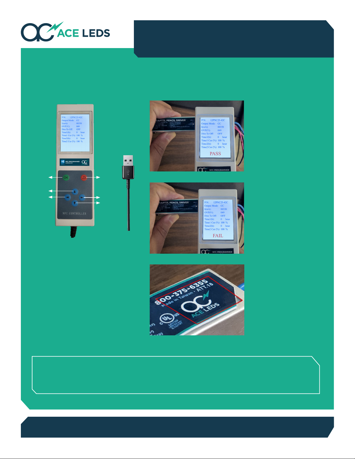
Once all the settings are correct, press the red “Back”
button to return to the default programming screen.
From here, if you press the green “OK” button, the
programmer will “BEEP” 3 times and you should
see a red “ FA IL” message on the bottom of the screen.
This means that the programmer couldn’t detect
or program the NFC chip successfully. Look for the
ACELEDs logo, which is placed directly above the NFC
chip of the driver and should be in the bottom right hand
corner. Place the top part of the programmer against
the label, and press the green “OK” button. If the driver
is programmed correctly, the device will “BEEP” once
and you will see a red “PASS” message on the bottom.
The driver will then be programmed to the newest
settings. To read the driver, place the programmer
above the ACELEDs logo, and press the blue “▲“on the
default programming screen and the programmer will
display all of the currently programmed settings.
STEP 3: Programming / Reading the Driver
The NFC Programmer requires 5V DC power source to
turn on. Simply connect the programmer into any USB
power receptacle, and it will turn on immediately after.
During and after start-up, the 2 following screens should
appear:
Pressing the red “Back” button will bring you to a new
screen, which is the conguration screen.
The second screen will show all of the parameters and
settings, as well as which driver model the programmer
is set to program.
From here, you can navigate using the blue “▲”and “▼”
buttons which will allow you see all of the available settings.
Although there are a total of 10 parameters available, for
the sake of simplicity, we will only focus on parameters
#1 and #3, which are the only parameters necessary for
programming a constant current LED driver with this
programmer.
#1 – Driver Type:
The selected setting will be highlighted in red. To change it,
press the green “OK” button. From here, you can use the
Figure 2.
This screen
shows which
version of the
programmer
is being used,
as well as its
release date.
Figure 3.
This is the
default screen
used for
programming.
This screen
shows all of
the current
settings and
parameters
that can be
programmed
onto a driver.
STEP 1: Power Up the Programmer
STEP 2: Setting the Parameters
Figure 4.
This is the conguration
screen, which allows you
to set multiple driver
settings.
Table of contents
Other ACE LEDS Lighting Equipment manuals
Popular Lighting Equipment manuals by other brands

MJ LED LIGHTNING
MJ LED LIGHTNING MJ-2037C user manual

EuroLite
EuroLite DTB-403 user manual

GKOLED
GKOLED GKOALG5 Series installation guide

ORGA
ORGA L550 Installation, operation and maintenance manual

Cooper
Cooper HALO SLFS1AM1B instruction manual

kim lighting
kim lighting 4300 Series installation instructions