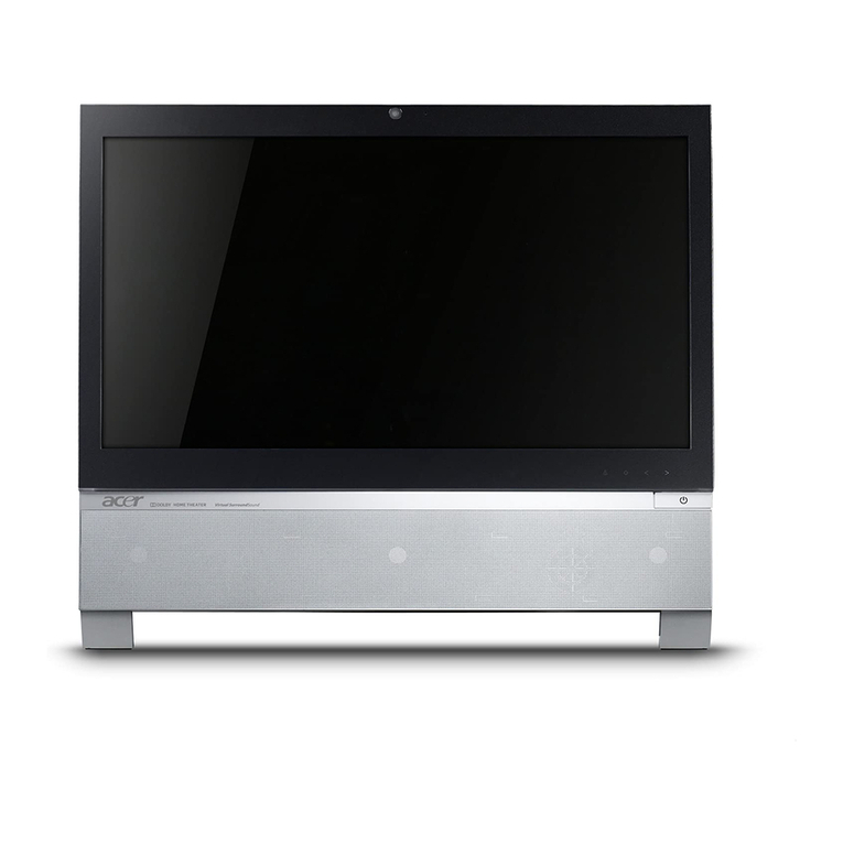
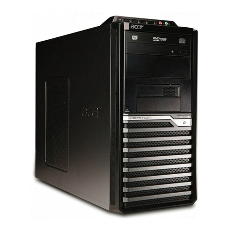
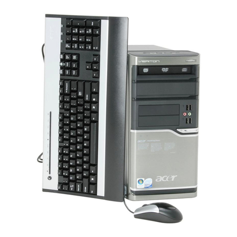
Acer Aspire T680 User manual

Aspire T680
AcerPower FG
Service Guide
PRINTED IN TAIWAN
Service guide files and updates are available
on the AIPG/CSD web; for more information,
please refer to http://csd.acer.com.tw

II
Revision History
Please refer to the table below for the updates made on Aspire T680 & AcerPower FG service guide.
Date Chapter Updates

III
Copyright
Copyright © 2005 by Acer Incorporated. All rights reserved. No part of this publication may be reproduced,
transmitted, transcribed, stored in a retrieval system, or translated into any language or computer language, in
any form or by any means, electronic, mechanical, magnetic, optical, chemical, manual or otherwise, without
the prior written permission of Acer Incorporated.
Disclaimer
The information in this guide is subject to change without notice.
Acer Incorporated makes no representations or warranties, either expressed or implied, with respect to the
contents hereof and specifically disclaims any warranties of merchantability or fitness for any particular
purpose. Any Acer Incorporated software described in this manual is sold or licensed "as is". Should the
programs prove defective following their purchase, the buyer (and not Acer Incorporated, its distributor, or its
dealer) assumes the entire cost of all necessary servicing, repair, and any incidental or consequential
damages resulting from any defect in the software.
Acer is a registered trademark of Acer Corporation.
Intel is a registered trademark of Intel Corporation.
Pentium 4 and Celeron are trademarks of Intel Corporation.
Other brand and product names are trademarks and/or registered trademarks of their respective holders.

IV
Conventions
The following conventions are used in this manual:
SCREEN
MESSAGES
Denotes actual messages that appear
on screen.
NOTE Gives bits and pieces of additional
information related to the current
topic.
WARNING Alerts you to any damage that might
result from doing or not doing specific
actions.
CAUTION Gives precautionary measures to
avoid possible hardware or software
problems.
IMPORTANT Reminds you to do specific actions
relevant to the accomplishment of
procedures.

V
Preface
Before using this information and the product it supports, please read the following general information.
1. This Service Guide provides you with all technical information relating to the BASIC CONFIGURATION
decided for Acer's "global" product offering. To better fit local market requirements and enhance product
competitiveness, your regional office MAY have decided to extend the functionality of a machine (e.g.
add-on card, modem, or extra memory capability). These LOCALIZED FEATURES will NOT be covered
in this generic service guide. In such cases, please contact your regional offices or the responsible
personnel/channel to provide you with further technical details.
2. Please note WHEN ORDERING FRU PARTS, that you should check the most up-to-date information
available on your regional web or channel. If, for whatever reason, a part number change is made, it will
not be noted in the printed Service Guide. For ACER-AUTHORIZED SERVICE PROVIDERS, your Acer
office may have a DIFFERENT part number code to those given in the FRU list of this printed Service
Guide. You MUST use the list provided by your regional Acer office to order FRU parts for repair and
service of customer machines.

VII
Table of Contents
Chapter 1 System Specifications 1
Overview . . . . . . . . . . . . . . . . . . . . . . . . . . . . . . . . . . . . . . . . . . . . . . . . . . . . . . . . . . 1
Features . . . . . . . . . . . . . . . . . . . . . . . . . . . . . . . . . . . . . . . . . . . . . . . . . . . . . . . . . . 2
Block Diagram . . . . . . . . . . . . . . . . . . . . . . . . . . . . . . . . . . . . . . . . . . . . . . . . . . . . . . 5
MainBoard Placement . . . . . . . . . . . . . . . . . . . . . . . . . . . . . . . . . . . . . . . . . . . . . . . . 7
Aspire T680 Front Panel . . . . . . . . . . . . . . . . . . . . . . . . . . . . . . . . . . . . . . . . . . . . . . 9
AcerPower FG . . . . . . . . . . . . . . . . . . . . . . . . . . . . . . . . . . . . . . . . . . . . . . . . . . . . . 10
Rear Panel. . . . . . . . . . . . . . . . . . . . . . . . . . . . . . . . . . . . . . . . . . . . . . . . . . . . . . . . 11
System Peripherals . . . . . . . . . . . . . . . . . . . . . . . . . . . . . . . . . . . . . . . . . . . . . . . . . 12
Mouse (PS/2 or USB, manufacturing option). . . . . . . . . . . . . . . . . . . . . . . .12
Keyboard (PS/2 or USB, manufacturing option) . . . . . . . . . . . . . . . . . . . . .12
Speakers . . . . . . . . . . . . . . . . . . . . . . . . . . . . . . . . . . . . . . . . . . . . . . . . . . .13
Acer eRecovery . . . . . . . . . . . . . . . . . . . . . . . . . . . . . . . . . . . . . . . . . . . . . . . . . .14
Create backup . . . . . . . . . . . . . . . . . . . . . . . . . . . . . . . . . . . . . . . . . . . . . . .14
Restore from backup . . . . . . . . . . . . . . . . . . . . . . . . . . . . . . . . . . . . . . . . . .14
Create factory default image CD . . . . . . . . . . . . . . . . . . . . . . . . . . . . . . . . .14
Re-install bundled software without CD . . . . . . . . . . . . . . . . . . . . . . . . . . . .15
Change Password . . . . . . . . . . . . . . . . . . . . . . . . . . . . . . . . . . . . . . . . . . . .15
Acer disc-to-disc recovery . . . . . . . . . . . . . . . . . . . . . . . . . . . . . . . . . . . . . . . . . .16
Restore without a Recovery CD. . . . . . . . . . . . . . . . . . . . . . . . . . . . . . . . . .16
Multilingual operating system installation. . . . . . . . . . . . . . . . . . . . . . . . . . .16
Hardware Specifications and Configurations . . . . . . . . . . . . . . . . . . . . . . . . . . . .17
Jumper Setting. . . . . . . . . . . . . . . . . . . . . . . . . . . . . . . . . . . . . . . . . . . . . . . . . . .23
Connector . . . . . . . . . . . . . . . . . . . . . . . . . . . . . . . . . . . . . . . . . . . . . . . . . . . . . .24
Chapter 2 System Utilities 27
Entering Setup . . . . . . . . . . . . . . . . . . . . . . . . . . . . . . . . . . . . . . . . . . . . . . . . . . . . 28
Product Information . . . . . . . . . . . . . . . . . . . . . . . . . . . . . . . . . . . . . . . . . . . . . . . . . 29
Standard CMOS Features . . . . . . . . . . . . . . . . . . . . . . . . . . . . . . . . . . . . . . . . . . . 30
Advanced BIOS Features . . . . . . . . . . . . . . . . . . . . . . . . . . . . . . . . . . . . . . . . . . . . 32
Advacned Chipset Features . . . . . . . . . . . . . . . . . . . . . . . . . . . . . . . . . . . . . . . . . . 38
Integrated Peripherals . . . . . . . . . . . . . . . . . . . . . . . . . . . . . . . . . . . . . . . . . . . . . . 39
Power Management Setup . . . . . . . . . . . . . . . . . . . . . . . . . . . . . . . . . . . . . . . . . . . 41
Frequency Control . . . . . . . . . . . . . . . . . . . . . . . . . . . . . . . . . . . . . . . . . . . . . . . . . . 43
PnP/PCI Configurations . . . . . . . . . . . . . . . . . . . . . . . . . . . . . . . . . . . . . . . . . . . . . 44
Load Default Settings . . . . . . . . . . . . . . . . . . . . . . . . . . . . . . . . . . . . . . . . . . . . . . . 45
PC Health Status . . . . . . . . . . . . . . . . . . . . . . . . . . . . . . . . . . . . . . . . . . . . . . . . . . 46
Set Supervisor/User Password . . . . . . . . . . . . . . . . . . . . . . . . . . . . . . . . . . . . . . . . 47
Save & Exit Setup . . . . . . . . . . . . . . . . . . . . . . . . . . . . . . . . . . . . . . . . . . . . . . . . . . 48
Exit Without Saving . . . . . . . . . . . . . . . . . . . . . . . . . . . . . . . . . . . . . . . . . . . . . . . . . 49
Chapter 3 Machine Disassembly and Replacement 50
General Information . . . . . . . . . . . . . . . . . . . . . . . . . . . . . . . . . . . . . . . . . . . . . . . . 51
Disassembly Procedure . . . . . . . . . . . . . . . . . . . . . . . . . . . . . . . . . . . . . . . . . . . . . 52
Removing the Housing. . . . . . . . . . . . . . . . . . . . . . . . . . . . . . . . . . . . . . . . .52
Removing the Front Panel . . . . . . . . . . . . . . . . . . . . . . . . . . . . . . . . . . . . . .52
Removing the Cables from the Mainboard . . . . . . . . . . . . . . . . . . . . . . . . .53
Removing the Cables from the Device . . . . . . . . . . . . . . . . . . . . . . . . . . . .53
Removing the ODD . . . . . . . . . . . . . . . . . . . . . . . . . . . . . . . . . . . . . . . . . . .54
Removing the FDD . . . . . . . . . . . . . . . . . . . . . . . . . . . . . . . . . . . . . . . . . . .54
Removing the Card Reader . . . . . . . . . . . . . . . . . . . . . . . . . . . . . . . . . . . . .54
Removing the HDD . . . . . . . . . . . . . . . . . . . . . . . . . . . . . . . . . . . . . . . . . . .54
Removing the DIMM . . . . . . . . . . . . . . . . . . . . . . . . . . . . . . . . . . . . . . . . . .55


VIII
Table of Contents
Removing the USB Module . . . . . . . . . . . . . . . . . . . . . . . . . . . . . . . . . . . . .55
Removing the Heatsink and CPU . . . . . . . . . . . . . . . . . . . . . . . . . . . . . . . .55
Removing the System FAN . . . . . . . . . . . . . . . . . . . . . . . . . . . . . . . . . . . . .56
Removing the Power Supply . . . . . . . . . . . . . . . . . . . . . . . . . . . . . . . . . . . .56
Removing the Mainboard. . . . . . . . . . . . . . . . . . . . . . . . . . . . . . . . . . . . . . .56
Chapter 4 Troubleshooting 57
Power-On Self-Test (POST) . . . . . . . . . . . . . . . . . . . . . . . . . . . . . . . . . . . . . . . . . . 58
POST Check Points . . . . . . . . . . . . . . . . . . . . . . . . . . . . . . . . . . . . . . . . . . . . . . . . . 59
POST Error Messages List . . . . . . . . . . . . . . . . . . . . . . . . . . . . . . . . . . . . . . . . . . . 65
Error Symptoms List . . . . . . . . . . . . . . . . . . . . . . . . . . . . . . . . . . . . . . . . . . . . . . . . 67
Chapter 5 FRU (Field Replaceable Unit) List 72
Exploded Diagram . . . . . . . . . . . . . . . . . . . . . . . . . . . . . . . . . . . . . . . . . . . . . . . . . 73

Chapter 1 1
Overview
This model is a consumer/ commercial-oriented desktop PC built with latest, high-performance technology
for easier and more enjoyable consumer environment.
Regarding the “Stable Technology”, we choose Intel Pentium 4 LGA775 (socket T) processor,
Intel 915GV+ICH6 (Prescott/ Cedar Mill) chipset architecture. This combination can run at 800MHz
Front Side Bus and provides On-Board VGA and discret VGA support, which provides better performance
than other processors. We also provide one PCI-Express x16 slot, three PCI slots (support PCI 2.2 spec.),
4 Dual Channel DDR 2 memory slots (support up to 4GB), P-ATA devices (HDD/ODD),
four S-ATA devices (HDDs), on board 10/100/1000 LAN and on board Audio function.
System Specifications
Chapter 1

2Chapter 1
Features
CPU
TSocket Type : Intel Socket T
TSupports Intel Pentium 4 Prescott 775 / FSB 533/800MHz
TSupports Intel Celeron Prescott 775 / FSB 533MHz
TPentium 4 2.66GHz ~3.8GHz speed
TCeleron D 2.53GHz ~ 3.2GHz
TL2 Cache varies with CPU from 1MB to 2MB
Chipset
TNorthbridge: Intel 915GV
TSouthbridge: ICH6
Memory
TSocket Type : DDR2 , 1.8 Voltage
TSocket Quantity : 2
TCapacity support : 128MB ~ 4GB
TSupport Memory Speed : 533/400 MHz
Graphic Solution
TIntegrated VGA
TATI x300, x600
TnVidia 6600
Slots
T3 PCI slot
T1 PCIE 16x slot
FDD
TOne 1.44MB 3.5” device
TAllow connection of 2 FDD devices

Chapter 1 3
Audio
TController: Intel ICH6
TCodec : Realtek ALC880H
TConnector support Lin in/ Lin out, Microphone In (front)(Default)
THeadphone Out (front)(Default), Headphone In (rear),
TWhen earphone is plugged in the front access audio jack, speaker-out will mute automatically.
T5.1 Channel Audio Support
TReserved disable function on BIOS side. Default is enabled.
LAN
TController : ICH6
TLAN Chip : Realtek 8100S
TShould be worked under 10/100/1000 Mbs environment
TReserved disabled function on both hardware & BIOS side. Default is enabled
USB
TController : Intel ICH6
TConnectors Quantity : 8 (4 on rear connector, 4 on-board header)
T2 for front daughter board
T1 for Multi-Media card reader
TUSB 2.0/1.1

4Chapter 1
System LED Definition
System S State Wake-Up devices supported with default setting
S1 (Idle) TPower Button : Enabled
TPS/2 Keyboard : Enabled
TUSB Keyboard : Enabled
TRTC : Disabled
TLAN : Disabled
TModem (Ring) : Disabled
S3 (Suspend to RAM) TPower Button : Enabled
TPS/2 Keyboard : Enabled
TUSB Keyboard : Enabled
TLAN : Disabled
TModem (Ring) : Disabled
S4 (Suspend to Disk) TPower Button : Enabled
TPS/2 Keyboard : Enabled
TUSB Keyboard : Disabled
TRTC : Disabled
TLAN : Disabled
TModem (Ring) : Disabled
S5 (Shut Down) TPower Button : Enabled
TPS/2 Keyboard : Enabled
TUSB Keyboard : Enabled
TRTC : Disabled
TLAN : Disabled
TModem (Ring) : Disabled
Special Design Specifications
Item Description
Thermal Design TDynamic FAN speed control by hardware monitor
TCPU Over-temperature (over 120oC) power off
protectio
Power On / Wake-up event TPower Button : S1/S3/S4/S5
TPS/2 Keyboard : S1/S3/S4/S5
TRTC : S1/ S5
TLAN : S1/S3/S5
TModem (Ring) : S1/S3/S5

Chapter 1 5
On-Board Connector
TRear I/O Connectors
T1 PS/2 Keyboard Port, 1 PS/2 Mouse Port
T1 Parallel Port, 1 Serial Port
T1 VGA Port
T1 10/100/1000 LAN Port
T4 USB Ports
T1 Line-in/Line-out/Mic-in port
TOn-Board Connectos
T1 CPU Socket
T4 Memory Slots
T1 PCI Express x16 Slot
T3 PCI Slots
T1 FDD Slot
T1 PATA IDE Slots
T4 SATA IDE Slots
T1 2*5 pin USB pin connector
T1 serial port pin connector (2nd serial port)
T1 Aux-In 4pin connector (CD-ROM Audio Input)
T1 3-pin or 4-pin CPU Fan connector
T1 3-pin System FAN connector
T1 24-pin/4-pin ATX interface PS3/PS2 SPS connector
T1 2 pin LAN activity monitor connector
T2 reserved 2pin GPIO connector
TColor management for on board connector

6Chapter 1
Block Diagram
P4 Processor
LGA 775 pin
INTEL
INTEL
i915GV
1210pin FC-BGA
INTEL
ICH6
609pin EBGA
BW : 2GB/s (Support Lsoch)
DDIMM1: DDR Socket 184P
DDIMM2 : DDR Socket 184P
USBLAN
8 ports
USB4
2 ports
USB V2.0
IDE1 40pin
Up to Ultra ATA/100
Two IDE Channel
AC' 97 & Lan I/F
BW : 133MB/s @Freq : 33MHz
PCI1 Slot 120pin @ AD17
PCI2 Slot 120pin @ AD18
10/100
Lan
RJ45
USBLAN
W83627THF
Super I/O
128pin PQFP
LPC bus
FWH
intel
32pin PLCC
ALC880
Audio Codec
PCB : 244 x 244 mm ; 4 layers
USB3
2 ports
DDIMM3: DDR Socket 184P
DDIMM4 : DDR Socket 184P
VGA (G only)
USB2
2 ports
USB1
2 ports
VIA 1394
HEADER
CONN/
SATA1 7Pin
SATA2 7pin
BW : 6.4GB/s @ FSB : 800MHz & Freq : 200MHz
BW : 8.5GB/s @ DDR2 :400/533MHz
BW : 6.4GB/s @ DDR : 333/400MHz
DEVICE
PCI1
PCI2
LAN
1394
IDSEL
17
INT#
C/D/E/F
REQ#
PREQ-0
GNT#
PGNT-0
18 D/E/F/G PREQ-1 PGNT-1
21 PREQ-4 PGNT-4
20 PREQ-3 PGNT-3
SATA3 7Pin
SATA4 7pin
SIZE : Min 128MB (ONE 256Mb X 16 Single-Sided DEVICES)
SIZE : Max 4GB (Four 512Mb X 8 Double-Sided DEVICES)
Analong Display
RAMDAC: 400MHz
Resolutions Up To 2048x1536@75Hz
BW : 150MB/s
TPM 1.1
PSC, Tejas -
BW : 4.1GB/s @ FSB : 533MHz & Freq : 133MHz
D
E
PCI3 19 F/E/H/G PREQ-2 PGNT-2
PCI3 Slot 120pin @ AD19
(OPTION)
PCIEx1
Center/Bass out
Surround
Side-Surround
Line in
Line out
Mic in

Chapter 1 7
MainBoard Placement

8Chapter 1
Item Label Component
1 CPU Socket LGA775 socket for Pentium 4 CPUs
2 CPUFAN1 CPU cooling fan connector
3 SYS_FAN System fan connector
4 DIMM1~4 240-pin DDR2 SDRAM slots
5 ATX1 Standard 24-pin ATX power connector
6 FDD Floppy diskette drive connector
7 IDE1 Primary IDE channel
8 CLR_CMOS Clear CMOS jumper
9 SATA1~4 Serial ATA connectors
10 F_PANEL1 Panel connector for case switches and LEDs
11 COM2 Onboard serial port header
12 F_USB1~2 Front Panel USB headers
13 BIOS_WP BIOS flash protect jumper
14 CDIN1/AUXIN CD-in connector
15 AUDIO1 Front panel audio header
16 PCI1~3 32-bit add-on card slots
17 PCIEX16 PCI Express x16 slot
18 ATX12V Auxiliary 4-pin power connector

Chapter 1 9
Aspire T680 Front Panel
NOTE: The specifications above are for reference only. The exact configuration of your PC depends on the
model purchased.
No. Description No. Description
1 Optical drive 2 Floppy drive
3 Power button 4 Speaker or headphone jack
5 Microphone jack 6 USB ports
No. Description No. Description

10 Chapter 1
AcerPower FG Front Panel
No. Description
1 Power-Button
2 USB Ports
3 Microphone-in out ( Front )
4 Speaker-out/Line-out Port
5 CD Reject-Button
6IRReceriver
7 Optical drive Door
8 3.5 inch Floppy disk drive
9 Floppy drive LED
10 Floppy drive eject button

Chapter 1 11
Rear Panel
No. Description
1 6 audio jacks (7.1 HD audio jack)
2RJ45
3 USB ports
4 CRT/LCD port
5 Parallel port
6 Serial port
7 PS/2 keyboard
8 PS/2 mouse
9 Power code port
10 SPDIF port
11 Recovery Switch Holder
12 Lock Handle

12 Chapter 1
System Peripherals
The Aspire T670 and AcerPower FE computer consist of the system itself, and system peripherals, like a
mouse, keyboard and a set of speakers (optional). This section provides a brief description of the basic
system peripherals.
Mouse (PS/2 or USB, manufacturing option)
The included mouse is a standard two-button wheel mouse. Connect the mouse to the PS/2 mouse port or
USB port on the back panel of the system.
Keyboard (PS/2 or USB, manufacturing option)
Connect the keyboard to the PS/2 keyboard port or USB port on the back panel of the system.

Chapter 1 13
Speakers
For systems bundled with speakers, before powering on the system, connect the speaker cable to the audio
out (external speaker) port on the back panel of the system.
For more detailed information about the speakers, please refer to the included operating instructions.
NOTE: speakers are optional and the appearance might be different depending on the actual product.
Note:
This manual suits for next models
2
Table of contents
Other Acer Desktop manuals

Acer
Acer Aspire 3300S User manual

Acer
Acer Aspire 3300 User manual

Acer
Acer Aspire RC500 User manual

Acer
Acer Veriton 5600G Training manual

Acer
Acer VERITON 7600 User manual

Acer
Acer Aspire M3710 User manual

Acer
Acer Aspire M5630 User manual

Acer
Acer Aspire T130 User manual

Acer
Acer Aspire T690 User manual

Acer
Acer Aspire M3920 User manual

Acer
Acer Aspire E650 User manual

Acer
Acer Aspire Z3620 User manual

Acer
Acer Altos 330 Series User manual

Acer
Acer Aspire X1930 User manual

Acer
Acer Aspire T330 User manual

Acer
Acer Power Sx User manual

Acer
Acer 5600 series User manual

Acer
Acer Aspire M3420 User manual

Acer
Acer Aspire T135 Training manual

Acer
Acer ASPIRE Z3750 User manual