Acer 12000 User manual

& K DSWHU
System Board
System Board 1-1
1.1 Features
The M21A is a dual-processor system board built on an extended ATX
baseboard utilizing two Intel Pentium II Xeon processors running at
400/100 and 450/100 MHz. It is integrated with the Intel 440GX system
controller, which consists of the PCI/AGP controller and the PCI/ISA
IDE accelerator (PIIX4E).
The Pentium II Xeon processor like its predecessor, the Pentium Pro
and Pentium II processor, implements a Dynamic Execution micro-
architecture - a unique combination of multiple branch prediction, data
flow analysis, and speculative execution. This means that the Pentium
II Xeon can deliver higher performance than the Pentium processor
while maintaining binary compatibility with all previous Intel
Architecture processors.
Also, the Pentium II Xeon processor is available in 512K, 1MB, and
2MB L2 cache options with the introduction of the Slot 2 socket.
Unlike Slot 1 Pentium IIs, which access the L2 at half the processor
speed, the Slot 2 access the L2 at full processor clock speed.
The PCI/AGP controller host bus interface supports a Pentium II Xeon
processor with 100 MHz bus frequency. It also provides a 72-bit
DIMM that supports synchronous DRAM (SDRAM) DIMMs. The
PCI/AGP controller introduces a new technology, which is the
Accelerated Graphics Port (AGP) interface. Supporting up to
533MB/sec MHz data transfer rate, the AGP interface boosts graphics
performance.

1-2 User’s Guide
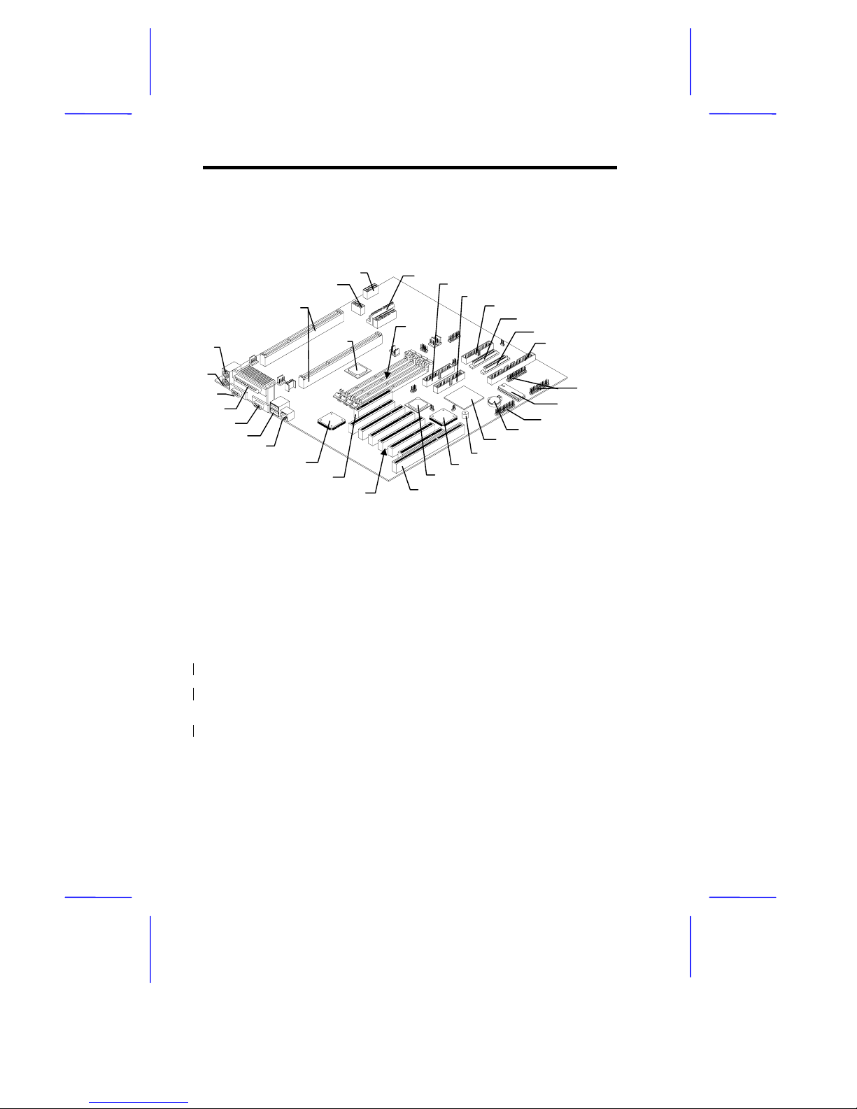
The PIIX4E is a multifunctional PCI device controller implementing
system functions including PCI IDE, universal serial bus (USB)
host/hub, and enhanced power management. It also supports Ultra
DMA/33 synchronous DMA-compatible devices.
The four DIMM sockets on board allow memory upgrade to a
maximum of 2048 MB and supports 72-bit DIMM using synchronous
DRAM (SDRAM) DIMMs.
Two 16-bit fast wide Ultra-2 SCSI (Small Computer System Interface)
and an 8-bit fast narrow SCSI comes with the system board to
connect SCSI devices.
The system board also supports the USB (Universal Serial Bus)
connector, and other standard features such as two UART NS16C550
serial ports, one enhanced parallel port with Enhanced Parallel Port
(EPP)/Extended Capabilities Port (ECP) feature, a diskette drive
interface, and two embedded hard disk interfaces. The board also
includes a built-in 10/100 Mb/s Intel 82558 LAN chip that supports
Wake-On-LAN (WOL).
The system supports the power-management function that conforms
to the power-saving standards of the U.S. Environmental Protection
Agency (EPA) Energy Star program. It also offers the Plug-and-Play
feature. This feature saves the user from configuration troubles, thus
making the system more user-friendly. The system board supports two
optional features, ASM Pro and Remote Diagnostic
Management (RDM), that allow better server management. The ASM
Pro detects problems in CPU thermal condition, CPU working voltage
detection (±12V/±5V/3.3V/1.5V), and PCI bus utilization calculation. It
also detects if the CPU fan or the chassis fan malfunctions. RDM
allows execution of the RDM diagnostic program from a remote RDM
station to fix detected problems or to reboot the system.
The system is fully compatible with MS-DOS V6.X, Novell Netware,
Novel SFT III, SCO UNIX, Windows NT and Windows 95/98 operating
systems

System Board 1-3
1.2 Major Components
The system board has the following major components:
•Supports dual Intel Pentium II Xeon processors running at 400 or
450 MHz with integrated 512K, 1MB or 2MB L2 write-back cache
•Four DIMM sockets that accept 16-, 32-, 64- 128-, 256 and
512MB DIMMs with a maximum of 2048 MB system memory
•One ISA, six PCI, and one AGP bus slots (one PCI and ISA
shared slot)
•512-KB Flash ROM for system BIOS
•System clock/calendar with battery backup
•One 50-pin fast SCSI and two 68-pin Ultra2 SCSI
•I/O APIC device for SMP interrupt support
•Integrates an enhanced PCI local bus IDE controller
•Intel 440GX chipset supports AGP (Accelerated Graphics Port)
and Ultra DMA/33 functions
•10/100 Mb/s Intel 82558 LAN chip that supports Wake-On-LAN
(WOL)
•Two 24-pin RDM interfaces
•IDE hard disk and diskette drive interfaces
•Auxiliary power connector for 280W SPS and ATX power supply
•Super I/O, SCSI, memory, Advanced Server Management (ASM)
and LAN Desk Client Management (LDCM) controller chipsets
•External ports:
•USB connector •PS/2-compatible keyboard port
•RJ-45 jack •PS/2-compatible mouse port
•Parallel port •Serial port 1 and 2

1-4 User’s Guide
1.3 Layout
Figure 1-1 shows the system board components.
1 Mouse port
2 Keyboard port
3 Serial port 1
4 Parallel port
5 Serial port 2
6 USB connector
7 RJ-45
8 LAN controller
9 AGP slot
10 PCI slots
11 ISA slots
12 Intel 82371EB PIIX4E (PCI-
ISA bridge)
13 DEC 21152 (PCI-PCI bridge)
14 Buzzer
15 SCSI controller
16 Battery
17 Feature Connector (Intel SMM Card)
18 System BIOS
19 RDM connectors
20 Channel A fast/narrow SCSI
connector (50 pin)
21 Channel A Ultra-wide/Ultra-1 SCSI
connector (68 pin)
22 Channel B Ultra-wide/Ultra-1 SCSI
connector (68 pin)
23 Wide SCSI connector (68 pin)
24 EIDE connector 2 (secondary)
25 EIDE connector 1 (primary)
26 DIMM sockets
27 Intel 443GX system controller
28 Power connector 1
29 Power connector 2
30 Power connector
3
31 Slot 2 CPU sockets
Figure 1-1 System Board Layout
1
2
3456
7
8
10
11
13
12
14
15
16
18
19
20
21
22
23
27
31
28
29
30
25
24
26
17
9

System Board 1-5
1.4 Jumpers and Connectors
1.4.1 Jumper and Connector Locations
Figure 1-2 shows the jumper and connector locations on the system
board.
Figure 1-2 System Board Jumper and Connector Locations
Jumpers are prefixed “JP”. Connectors are
prefixed “CN”. The blackened pin of a jumper
or connector represents pin 1.

1-6 User’s Guide
1.4.2 Jumper Settings
Table 1-1 lists the system board jumpers with their corresponding
settings and functions.
Table 1-1 System Board Jumper Settings
Jumper Setting Function
BIOS Logo
JP3 1-2*
2-3 Acer
OEM
Password Security
JP4 1-2
2-3* Check password
Bypass password
Boot Block Mode
JP5 1-2*
2-3 Disabled
Enabled
Sound Output
JP6 1-2*
2-3 Buzzer
Speaker
AlertPack Select
JP7 1-2/4-5
2-3/5-6* AlertPack and LM80
LM80 Only
SCSI CH. B Terminator
JP11 1-2*
2-3 Enabled
Disabled
*Default

System Board 1-7
1.4.3 Connector Functions
Table 1-2 lists the different connectors on the system board and their
respective functions.
Table 1-2 Connector Functions
Connector Function
CN1 Cabinet Fan Connector
CN3 Mouse and Keyboard Ports
CN4 280W Power Supply Connector-1
CN5 280W Power Supply Connector-2
CN6 ATX Power Connector
CN7 280W Power Supply Connector-3
CN9 Modem Card Ring-in Connector
CN10 Parallel (above), Serial 1(left), and Serial 2 (right)
ports
CN11 USB Connectors
CN12 CPU1 Fan Connector
CN13 CPU2 Fan Connector
CN14 RJ-45 (LAN) Port
CN15 Fail Report LED Connector
CN16 Cabinet Fan Connector
CN17 Cabinet Fan Connector
CN18 Cabinet Fan Connector
CN20 2 Color Power LED Connector
CN22 Redundant Power Status Connector
CN23 CPU1 Temperature Connector
CN24 CPU2 Temperature Connector
CN26 PCI Sound Card Interrupt and DMA Request
Connector
CN27 Primary IDE Connector
CN28 FDD Connector
CN29 SCSI Channel B Connector
CN30 Secondary IDE Connector

1-8 User’s Guide
Table 1-2 Connector Functions
Connector Function
CN32 SCSI Channel A Wide Connector
CN33 SCSI Channel A Narrow Connector
CN34 RDM LED Connector
CN35 External Speaker Connector
CN36 Hard Disk LED Connector
CN37 Hard Disk LED Connector
CN38 Power Switch Connector
CN39/47 RDM/ASM Module Connector
CN40 Wake-on-LAN (WOL) Connector
CN42 3-pin Standard Power Connector
CN43 Hard Disk LED Connector
CN44 Reset Button Connector
CN45 Feature Connector (Intel SMM Card)
CN46 Door Switch Connector

System Board 1-9
1.5 ESD Precautions
Always observe the following electrostatic discharge (ESD)
precautions before installing a system component:
1. Do not remove a component from its antistatic packaging until
you are ready to install it.
2. Wear a wrist grounding strap before handling electronic
components. Wrist grounding straps are available at most
electronic component stores.
Do not attempt the procedures described in
the following sections unless you are a
qualified technician.

1-10 User’s Guide
1.6 Installing and Removing the Pentium II
Xeon Processor
Intel’s Pentium II Xeon CPU is a Slot 2 processor that uses uses a
330-pin single edge connector which is a bit longer that a Slot 1
processor. Other than the size the major improvement of the Slot 2
processor is at the L2 cache. Pentium II Xeon processors access the
L2 cache at full clock speed, 400 MHz or 450 MHz, whereas a Slot 1
processor access the L2 at only half the CPU’s clock speed. This
significantly boost performance and speed.
1.6.1 Installing the Retention Mechanism
Follow these steps to install the retention mechanism:
1. Attach both the retention mechanism with the joint bar. Snap-in
the joint bar on both sides of the retention mechanism.
Figure 1-3 Inserting the joint bar on the Retention Mechanism
2. Insert both the retention mechanism into the Slot 2 sockets. Make
sure that the shafts of the retention mechanism with a O sign is
facing the external ports of the system board.

System Board 1-11
3. Align the metal brace beneath the system board along the Slot 2
retention holes and secure the retention mechanism with six
screws (see figure below). Install the last two screws when fitting
the system board to the housing.
Figure 1-4 Installing the Retention Mechanism
External Ports
O

1-12 User’s Guide
1.6.2 Installing an Intel Pentium II Xeon processor
Follow these steps to install a Pentium II Xeon processor:
1. Attach the fansink module to the Pentium II Xeon processor and
secure it with four screws.
Figure 1-5 Installing the Fansink
2. Insert the Pentium II Xeon processor into an empty Slot 2 socket.
Figure 1-6 Installing a Pentium II Xeon Processor
O

System Board 1-13
2. Carefully press down the Pentium II Xeon processor until it is
properly inserted into the socket.
3. Use the retention mechanism cover to secure the processor by
pressing it down until it locks with the retention mechanism as
shown below.
Figure 1-7 Installing Retention Mechanism Cover
The retention mechanism cover only fits one way. Both shafts of the
retention mechanism and the retention mechanism cover have a O
and a OO sign. Match the O on the cover with the O on the retention
mechanism first, then hooked them together and then insert the OO
side to the retention mechanism and make sure they are clipped.
1.6.3 Removing an Intel Pentium II Xeon processor
Follow these steps to remove a Pentium II Xeon processor:

1-14 User’s Guide
1. Unclip the retention mechanism cover.
Figure 1-8 Removing the Retention Mechanism Cover
2. Flip up both the plastic ear of the Pentium II Xeon processor. This
procedure detaches the processor from the socket.
Figure 1-9 Removing the Pentium II Xeon Processor

System Board 1-15
3. Carefully lift up and remove the Pentium II Xeon processor.
1.6.4 Installing and Removing the Terminator
Board
When you are not using all the Slot 2 sockets, you must install a
terminator board into each empty slot.
To install the terminator board:
1. Position the terminator board over the empty slot.
2. Carefully insert the golden fingers of the terminator board into the
slot until the board fits completely.
Figure 1-10 Installing a Terminator Board
3. Use the retention mechanism cover to secure the processor by
pressing it down until it locks with the retention mechanism. See
figure 1-6 for the illustration.
O

1-16 User’s Guide
The retention mechanism cover only fits one way. Both shafts of
the retention mechanism and the retention mechanism cover have
a o and a oo indicator. Match the O on the cover with the O on the
retention mechanism first, then hooked them together and then
insert the OO side to the retention mechanism and make sure they
are clipped.
To remove the terminator board:
1. Unclip the retention mechanism cover.
2. Flip up both the plastic ear of the terminator board. This
procedure detaches the terminator board from the socket.
3. Lift up and remove the terminator board.
Refer to section 1.6.3 for the illutrations.

System Board 1-17
1.8 Memory Upgrade
The four 168-pin sockets onboard support SDRAM-type DIMMs. You
may install 16-MB, 32-MB, 64-MB, 128-, 256-, or 512-MB (single and
double density) DIMMs for a maximum of 2048-MB system memory.
The SDRAM DIMMs should work under 3.3 volts only; 5 volt memory
devices are not supported. M21A supports both 100MHz standard
and registered SDRAM. However, please do not use them at the same
time.
Do not use both 66 MHz (unbuffered) and
100 MHz (registered) SDRAM together. This
might cause your system to malfunction.
Each of the sockets represents one independent bank. This allows
you to install DIMMs with different capacities to form a configuration.
1.8.1 Memory Configurations
Table 1-3 lists some system memory configurations. You may
combine DIMMs with various capacities to form other combinations.
Table 1-3 Memory Configurations
DIMM1 DIMM2 DIMM3 DIMM4 Total Memory
32 MB 32 MB
32 MB 32 MB 64 MB
32 MB 32 MB 32 MB 96 MB
32 MB 32 MB 32 MB 32 MB 128 MB
64 MB 64 MB
64 MB 64 MB 128 MB
64 MB 64 MB 64 MB 192 MB
64 MB 64 MB 64 MB 64 MB 256 MB

1-18 User’s Guide
Table 1-3 Memory Configurations
DIMM1 DIMM2 DIMM3 DIMM4 Total Memory
128 MB 128 MB
128 MB 128 MB 256 MB
128 MB 128 MB 128 MB 384 MB
128 MB 128 MB 128 MB 128 MB 512 MB
256 MB 256 MB
256 MB 256 MB 512 MB
256 MB 256 MB 256 MB 768 MB
256 MB 256 MB 256 MB 256 MB 1024 MB
512 MB 512 MB
512 MB 512 MB 1024 MB
512 MB 512 MB 512 MB 1536 MB
512 MB 512 MB 512 MB 512 MB 2048 MB
1.8.2 Installing a DIMM
To install a DIMM, align it with the socket and press it down until the
holding clips secure the DIMM in place.
The DIMM socket is slotted to ensure proper
installation. If you slip in a DIMM but it does
not completely fit, you may have inserted it
the wrong way. Reverse the orientation of
the DIMM.

System Board 1-19
Figure 1-11 Installing a DIMM
1.8.3 Removing a DIMM
To remove a DIMM, press the holding clips on both sides of the socket
outward to release the DIMM.
Place your forefingers on the top of the DIMM
before you press the holding clips to gently
disengage the DIMM from the socket.
Figure 1-12 Removing a DIMM

1-20 User’s Guide
1.8.4 Reconfiguring the System
Reconfigure the system after installing or removing DIMMs.
Follow these steps to reconfigure the system:
1. Reboot the system. A memory error message appears, indicating
that the total memory does not match the value stored in CMOS.
2. Press + + .
3. Press twice to exit Setup and reboot the system. The system
boots with the new memory configuration.
Other manuals for 12000
1
This manual suits for next models
2
Table of contents
Other Acer Motherboard manuals

Acer
Acer V66LT User manual

Acer
Acer V35LA-N User manual

Acer
Acer V58 Installation instructions

Acer
Acer Altos 12000 Series User manual

Acer
Acer V55 System User manual

Acer
Acer V38X User manual

Acer
Acer 486 User manual

Acer
Acer Altos 21000 Series User manual

Acer
Acer V55LA-2 User manual

Acer
Acer V60N User manual