1Chapter1
System Introduction
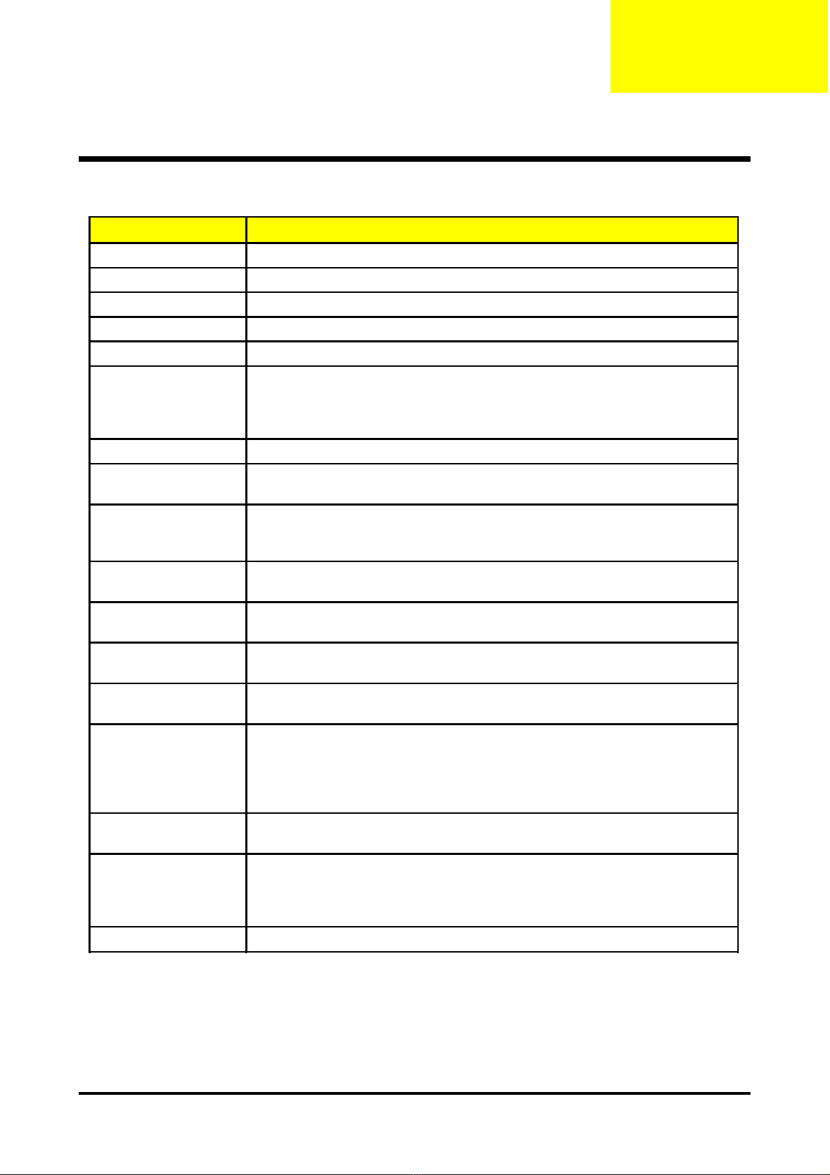
Technical Specification
Item Description
Dimensions (WxHxD) 230 x 122.8 x 238 mm
Weight Approx. 4.85 lbs (2.2 Kg)
Tilt Angle 7 degree with elevator mechanism
Keystone correction +/-16 degree (32 degree) (Horizontal)
Lamp Door Projection Lamp power supply shut off automatically when door open
Power Supply
Universal AC 100-240V ~ 50-60Hz with PFC input
200W for Philips UHP Lamp @ normal operation
Variance FAN speed control
(Depends on temperature variant)
Projection Lens F#2.7~3.0, f=21.83mm~23.81mm, 1.10X Mechanical Zoom Lens
Throw Distance 1.5m - 10m (Optical Performance)
1.5m - 12m (Mechanical Travel)
Brightness 1700 ANSI Lumens (Typical; Full Power Mode)
1170 ANSI Lumens (Typical; Eco Mode)
1300 ANSI Lumens (Engineering Minimum; Full Power Mode)
Contrast 1000 : 1 Full White and Black (Minimum; Full Power Mode)
1800 : 1 Full White and Black (Typical; Full Power Mode)
Uniformity 65% Japan standard (Minimum; Full Power Mode)
80% Japan standard (Typical; Full Power Mode)
Temperature Opterating : 5~35oC
Storage : -20~60oC
Maximum Humidity Operating : -5~35oC, 80%RH (Max.), non-condensing
Storage : -20~60oC, 80%RH (Max.), non-condensing
Acoustic noise level
38 dB(A) (Typical, Under 23 +/- 20C; Full Power Mode without DVD/wireless)
30 dB(A) (Typical, Under 23 +/- 20C; Eco Mode without DVD/wireless)
Noise measurement follows ISO7779, A-weighted sound pressure level
measurement, 7200 rpm color wheel rotational speed
Lamp Life 1500 hours min, 50% survival rate (Full Power Mode)
2000 hours min, 50% survival rate (Eco Mode)
Altitude
Operating : 0~2,500 ft for 5 oC~35oC
2,500~5,000 ft for 5 oC~30oC
5,000~10,000 ft for 5 oC~25oC
Storage : 40,000 ft (Max.)
MTBF Operating more than 12,000 hours (90% Confidence Level)
Chapter1