Automation Components, Inc.
2305 Pleasant View Road | Middleton, WI 53562
Phone: 1-888-967-5224 | Website: workaci.com
Page 3
OPERATION
Keypad
The keypad comes in a 2 button, 3 button, 4 button, 5 button,
or 6 button version. A 6 button keypad is needed for fan or
system mode. A 3 button or 5 button keypad is needed for
override mode.
Normal Mode
The LCD can display temperature, RH, occupied status, system
mode, and fan mode. The display conguration can be setup
when ordered or changed through the setup menu. The
backlight will turn on when the any key is pressed and will
turn o 10 seconds after the last key press.
Setpoint Mode
Press or to get into setpoint mode and
change the setpoint. If a temperature and RH setpoint are
used, pressing or and will switch
the large numbers between temperature and RH. If
temperature is displayed in the large numbers, the
temperature setpoint will adjust when or
is pressed. If RH is displayed in the large numbers, the RH
setpoint will adjust when or is pressed. If no
keys are pressed for 10 seconds the unit will automatically
return to normal operation.
Fan/System Mode
Press WWWW to change the fan or system setting. The fan or
system setting will start blinking after WWWW is pressed.
Press WWWW or WWWW and WWWW to switch between the
fan and system modes. The mode that is blinking will change
when WWWW or WWWW is pressed. Press WWWW to return
to normal operation. If no keys are pressed for 10 seconds the
unit will automatically return to normal operation.
Setup Mode
Press and hold WWWW for 5 seconds or press and hold WWW
and WWW for 10 seconds to enter setup mode. Once in the
setup menu, WWWW or WWWW will scroll through the setup
menu. Press WWWW or WWWW and WWW to enter menus.
Press WWW or WWW and WWWW to save menu selections.
GENERAL INFORMATION
The TUC2 provides temperature space monitoring with a
backlit LCD. The TUCH2 provides temperature and relative
humidity monitoring with a backlit LCD. Depending on the
conguration, the units can display and output Temperature,
Relative Humidity, Setpoint, Fan Speed, System Status, and
Occupied/Unoccupied Status.
The TUC2 and TUCH2 supports single temperature sensor
operation for several common sensor types and it provides the
exibility to choose from numerous setpoint output options.
The TUCH2 supports relative humidity output in all standard
analog signals at 2%, 3%, or 5% accuracy. A setup menu
provides easy output and display conguration changes.
MOUNTING INSTRUCTIONS
Carefully separate the cover from the base by pulling the
cover and base apart towards the bottom of the device. The
hex screws(1/16” Allen) may need to be turned in to release
the cover. Route the wires through the access hole in the
center of the base and screw them into the terminal blocks.
Refer to the wiring instructions to make the necessary
connections. Attach the base directly to drywall, or to a
standard 2”x 4” junction box using the hardware provided.
*Reference FIGURE 2 (p. 2)
WIRING INSTRUCTIONS
PRECAUTIONS
• Do not run the temperature sensor wiring in any
conduit with line voltage (24/120/230 VAC) if utilizing
resistance temperature signal.
• Remove power before wiring. Never connect or
disconnect wiring with power applied.
• When using a shielded cable, ground the shield only at
the controller end. Grounding both ends can cause a
ground loop.
• It is recommended you use an isolated UL-listed class 2
transformer when powering the unit with 24 VAC.
Version: 6.0
I0000621
WIRING INSTRUCTIONS (Continued)
Failure to wire the devices with the correct polarity when sharing transformers may result in damage to any
device powered by the shared transformer.
• If the 24 VDC or 24VAC power is shared with devices that have coils such as relays, solenoids, or other inductors,
each coil must have an MOV, DC/AC Transorb, Transient Voltage Suppressor (ACI Part: 142583), or diode placed
across the coil or inductor. The cathode, or banded side of the DC Transorb or diode, connects to the positive side
of the power supply.Without these snubbers, coils produce very large voltage spikes when de-energizing that can
cause malfunction or destruction of electronic circuits.
Carefully separate the cover from the base by pulling the cover and base apart towards the bottom of the device. ACI recommends
16 to 26 AWG twisted pair wires or shielded cable for all sensors. Be sure to connect the cable shield to the ground at the controller
only. The number of wires needed depends on the application, with 3 wires minimum required to support the outputs of theTUC2
unit. Generally, one wire is required for each output, one wire for power, and one wire for ground. All outputs are common ground
referenced. All wiring must comply with all local and National Electric Codes. After wiring, attach the cover to the base and turn
out the hex screw(1/16”Allen) until the cover cannot be removed. A 1/16”Hex driver is needed to secure the cover to the base.
Note: TUC2 units do not have RH or RHS terminal locations loaded.
Attach the required wires to the proper terminal locations. The TUC2 or TUCH2 supports three signal wires, ring, tip, and
shield. The number of wires needed depends on the application.
Note: ACI’s stats are not two-way communicating. Communication jacks allow the user to query and modify operating
parameters of the local room terminal unit from the portable operator’s terminal (laptop). This feature allows a technician to
commission or service the controller via the sensor.
Temperature Wiring Instructions
Signal wiring must be run separate from low and high voltage wires (24/120/230 VAC). All ACI thermistors and RTD
temperature sensors are non-position sensitive.
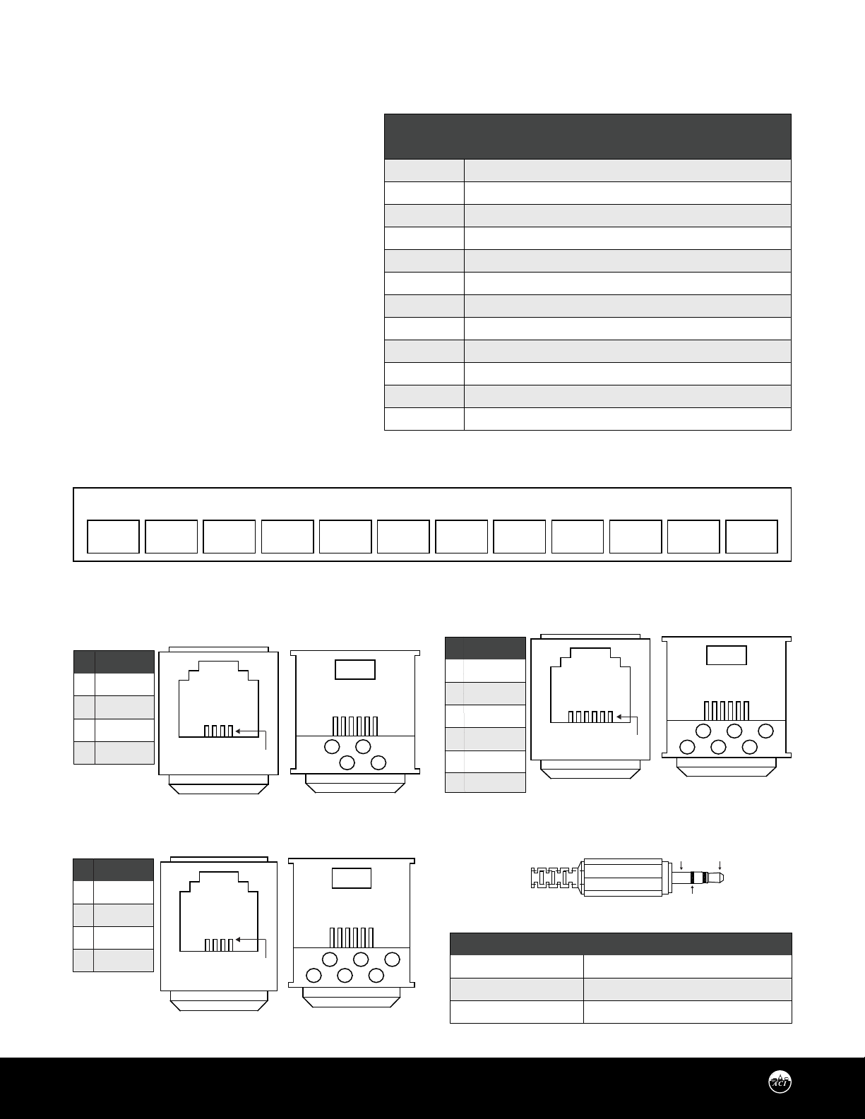
TABLE 1: TERMINAL BLOCK CONNECTIONS
FIGURE 5: 3.5 mm STEREO JACK
TABLE 2: STEREO JACK CONNECTIONS
FIGURE 4: COMMUNICATION JACK
FIGURE 3: TERMINAL BLOCK
WIRING INSTRUCTIONS
(Continued)
Note: If your TUC2 or TUCH2 has any output
congured with a 10V or Current output, the
voltage at the +V terminal must be at least +18
VDC.
Communication Jack Wiring
Before mounting the base to the wall, make the
appropriate connections to the communication
jack as described below. The number of wires
needed depends on the application. Using the
provided wire nuts, attach the required wires to the
proper connector pins used by your application.
*Reference FIGURE 4 (right, below)
+V T TS O/R F/A OFB S1 S2 S3 RH RHSCOM
TERMINAL
BLOCKS
+V
COM
T
TS
O/R
F/A
OFB
S1
S2
S3
RH
RHS
CONNECTIONS
+12 to +40 VDC or 20 to 28 VAC
Ground or signal common, 20 to 28 VAC
Temperature sensor signal to controller analog input
Temperature set point signal to controller analog input
Override signal to controller analog input
Fan signal to controller analog input
Occupied feedback signal from controller analog input
3.5 mm phone jack ring / Digital input or output
3.5 mm phone jack tip / Digital input or output
3.5 mm phone jack shield
RH signal to controller analog input
RH set point or system signal to controller analog input
# COLOR
1 BLACK
2 RED
3 GREEN
4 YELLOW
# COLOR
1 BLUE
2 BLACK
3 RED
4 GREEN
5 YELLOW
6 WHITE
*Reference FIGURE 3 (below)
2
1
4
3
6
5
1 3
2 4
1 3
2 4
FRONT VIEW REAR VIEWWIRING
# COLOR
1 BLACK
2 RED
3 GREEN
4 YELLOW
(4.1): 4 PIN, 4 CONNECTOR FRONT VIEW REAR VIEWWIRING
(4.2): 6 PIN, 6 CONNECTOR
FRONT VIEW REAR VIEWWIRING
(4.3): 6 PIN, 4 CONNECTOR
PIN 1
PIN 1
PIN 1
SHIELD TIP
RING
TERMINAL BLOCKS
S1 Terminal
S2 Terminal
S3 Terminal
JACK CONNECTIONS
Ring
Tip
Shield
OPERATION (Continued)
Setup Mode (Continued)
Press WWW to return to the previous menu. If no keys are pressed for 15 seconds the unit will automatically return to normal
operation.
Setup Menu
The full setup menu with descriptions of all the options is shown on page 6. The setup menu will change depending on the
conguration ordered. Only the menu options that apply to the conguration ordered will be shown. For instance, if no Fan
or System were ordered then those menu options would not appear.
Setup Lockout
In the setup menu there is an option to lockout setup mode. This can be used if you do not want users to change the setup.
Once the setup menu is locked, press WWW and WWW for 10 seconds to get into setup mode.
FULL SETUP MENU
The full setup menu with descriptions of all the options are shown on page 5. The setup menu will change depending on the
conguration ordered. Only the menu options that apply to the conguration ordered will be shown on the unit.
Press and hold SETUP for 5 seconds or press the UP arrow and DOWN arrow for 10 seconds to enter the Setup mode.
Press UP/DOWN arrows to scroll through top level menus.
Press SELECT to enter into Options Menus
Press UP/DOWN to scroll through Options Menu
Press SELECT to chose and save option in Options Menu
A full size version of this diagram can be found at:
www.workaci.com