manuals.online logo
Brands
  1. Home
  2. •
  3. Brands
  4. •
  5. aci
  6. •
  7. Accessories
  8. •
  9. aci DT2650 Installation instructions

aci DT2650 Installation instructions

Automation Components, Inc.
2305 Pleasant View Road | Middleton, WI 53562
Phone: 1-888-967-5224 | Website: workaci.com
Page 1
Version: 7.0
I0000681
MOUNTING INSTRUCTIONS (Continued)
Drill a 3/8" (9.53 mm) hole in the duct. Gently uncoil the copper tubing and insert the averaging element
through the hole until the foam pad is tight to the duct. The sensor should then be strung in a criss-cross
pattern throughout the duct using the mounting clips provided - see FIGURE 3 (p. 3).
Use a pattern that covers the greatest surface area of the duct to ensure that there is no stratication. When
bending the copper tubing, be careful that you use a gradual bend and that you DO NOT kink the copper
tubing. Bends should be a minimum of 2” (50.8 mm). Each unit includes nylon wire ties and mounts for
mounting. Optional copper capillary (ACI Item #
130525)
or universal plastic mounting clips (ACI Item
#
128248
) can be ordered. Plastic mounting clips will help insulate the copper sensing element from the
metal duct. The capillary clips help avoid kinks when bending. When using Flexible averaging, do not cover
the heatshrink that is located throughout the sensor (sensing points).
Drill pilot holes for the (2) mounting screws. Use the enclosure flange as a guide, or use the
dimensions listed below to measure out. Now fasten and insert (2) screws #8 x 3/4" TEK (provided and
recommended) through the mounting holes in the flange and tighten until the unit is held firmly to
the duct.
FIGURE 1: DIMENSIONS
STANDARD
NEMA 4X
FLEXIBLE AVERAGING
TEMPERATURE SERIES
Installation & Operation Instructions
DT2650
Phone: 1-888-967-5224
Website: workaci.com
1.88"
(47.752 mm)
2.25"
(57.15 mm)
3.20"
(81.28 mm)
5.25" (133.35 mm)
5.78" (146.812 mm)
Ø 0.19" (4X)
(4.826 mm)
Battery Positive Terminal
Internal Link Button
DT2650A
Heyco Water
Tight Fitting
Standard Enclosure
2.56"
(65.024 mm)
4.53" (115.062 mm)
2.23"
(56.642 mm)
Battery Positive Terminal
Internal Link Button
SST2630AE
Altech Water
Tight Fitting
NEMA 4X Enclosure
GENERAL INFORMATION
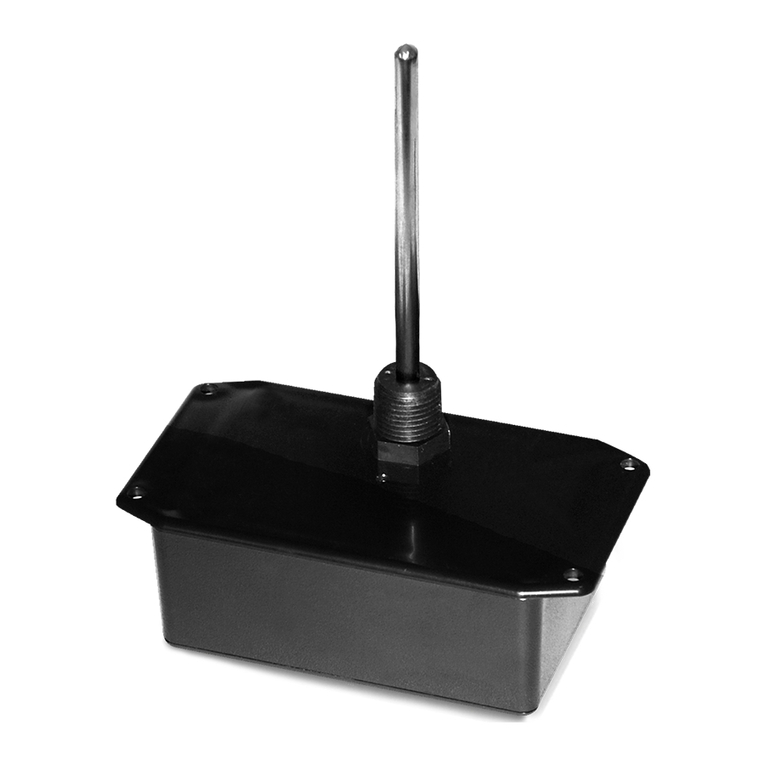
The DT2650 is a battery operated wireless
exible averaging temperature sensor using
900 MHz spread spectrum technology to
monitor averaged temperature in ducts. The
exible cable is 24’ long and has nine (9)
sensing points evenly spaced throughout
the length of the cable for maximum
coverage. The DT2650 is easy to install with
no wire runs or conduit needed. The DT2650
will send the temperature wirelessly to the
RM2432D receiver that converts the wireless
signal to voltage input for use with a DDC
controller, or to a transceiver which will send
the data to a BAS using BACnet™, Modbus, or
Lonworks®protocol. Transmission distance
in a typical building is 200-300 feet
horizontal depending on the layout and
construction of the building, and one oor
above and one oor below the transceiver.
Sensor distance and reliability can be
increased with the addition of a RR2552B(s)
repeater.
Wireless sensors should be installed within
200 to 300 feet of the receiver. RR2552
signal repeaters can be installed as to
increase transmission distance between
sensors and receivers.
MOUNTING INSTRUCTIONS
To select the proper sensor location, rst install and power the receiver. To activate the sensor insert the
battery observing the polarity. ACI’s Wireless system does not require any additional wireless equipment to
determine the proper location of the sensors.
While the sensor is attempting to connect to the receiver the Data-Link LED will blink rapidly 8–10 times
every 10 seconds. Once a connection has been established, the Data-Link LED will blink once to indicate
the data transmission has been received successfully. The Data-Link LED will continue to blink once for
every data transmission. The data transmission rate is programmed into the sensor (normally 1 minute
intervals). To manually initiate a data transmission press the push button switch located by the negative
terminal of the battery.
For optimal temperature measurement, follow these tips:
•Mount coil horizontal for vertical stratication.
•Mount coil vertical for horizontal stratication.
•The sensor must be spread evenly over the full duct.
•The entire length of the sensor coil must be installed completely inside the duct. Do not have any part of
the sensor exposed to exterior air.
•When installing the sensor near air-handling units, place the sensor downstream from the fan discharge.
The stratied airstream will be more uniform across the duct cross-section. If the air is not well-mixed, the
reading may be inaccurate.
Locate and record the sensor ID numbers located on a label inside the unit prior to mounting.
The sensor has a Low Battery LED that will start to blink continuously when the battery voltage is low. A
low battery signal is also sent to the receiver for remote indication that the battery should be replaced. If
the battery is not replaced in approximately 2 months, the battery voltage will become so low that the Low
Battery and Data-Link LEDs will not blink. Replace the battery and the Data-Link LED will start blinking
while the sensor is re-establishing communications with the receiver.
Then attach the cover of the sensor by installing the four screws.
PRECAUTIONS
SENSORS, REPEATERS AND RECEIVERS SHOULD NOT BE INSTALLED IN THE FOLLOWING AREAS:
• INSIDE METAL ENCLOSURE / PANEL
• INSIDE OR IMMEDIATELY NEXT TO ELEVATOR SHAFT / ELEVATOR BANKS
• IN FRONT OF OR IMMEDIATELY NEXT TO LARGE TREES OR LARGE BODY OF WATER
TRANSMISSION DISTANCE AND PERFORMANCE WILL BE DRASTICALLY REDUCED.
CAUTION:
DO NOT USE THIS PRODUCT IN ANY SAFETY RELATED APPLICATIONS WHERE HUMAN LIFE
MAY BE AFFECTED.
MOUNTING INSTRUCTIONS (Continued)
Drill a 3/8" (9.53 mm) hole in the duct. Gently uncoil the copper tubing and insert the averaging element
through the hole until the foam pad is tight to the duct. The sensor should then be strung in a criss-cross
pattern throughout the duct using the mounting clips provided - see FIGURE 3 (p. 3).
Use a pattern that covers the greatest surface area of the duct to ensure that there is no stratication. When
bending the copper tubing, be careful that you use a gradual bend and that you DO NOT kink the copper
tubing. Bends should be a minimum of 2” (50.8 mm). Each unit includes nylon wire ties and mounts for
mounting. Optional copper capillary (ACI Item #
130525)
or universal plastic mounting clips (ACI Item
#
128248
) can be ordered. Plastic mounting clips will help insulate the copper sensing element from the
metal duct. The capillary clips help avoid kinks when bending. When using Flexible averaging, do not cover
the heatshrink that is located throughout the sensor (sensing points).
Drill pilot holes for the (2) mounting screws. Use the enclosure flange as a guide, or use the
dimensions listed below to measure out. Now fasten and insert (2) screws #8 x 3/4" TEK (provided and
recommended) through the mounting holes in the flange and tighten until the unit is held firmly to
the duct.
Automation Components, Inc.
2305 Pleasant View Road | Middleton, WI 53562
Phone: 1-888-967-5224 | Website: workaci.com
Page 2
Version: 7.0
I0000681
GENERAL INFORMATION
The DT2650 is a battery operated wireless
exible averaging temperature sensor using
900 MHz spread spectrum technology to
monitor averaged temperature in ducts. The
exible cable is 24’ long and has nine (9)
sensing points evenly spaced throughout
the length of the cable for maximum
coverage. The DT2650 is easy to install with
no wire runs or conduit needed. The DT2650
will send the temperature wirelessly to the
RM2432D receiver that converts the wireless
signal to voltage input for use with a DDC
controller, or to a transceiver which will send
the data to a BAS using BACnet™, Modbus, or
Lonworks®protocol. Transmission distance
in a typical building is 200-300 feet
horizontal depending on the layout and
construction of the building, and one oor
above and one oor below the transceiver.
Sensor distance and reliability can be
increased with the addition of a RR2552B(s)
repeater.
Wireless sensors should be installed within
200 to 300 feet of the receiver. RR2552
signal repeaters can be installed as to
increase transmission distance between
sensors and receivers.
MOUNTING INSTRUCTIONS
To select the proper sensor location, rst install and power the receiver. To activate the sensor insert the
battery observing the polarity. ACI’s Wireless system does not require any additional wireless equipment to
determine the proper location of the sensors.
While the sensor is attempting to connect to the receiver the Data-Link LED will blink rapidly 8–10 times
every 10 seconds. Once a connection has been established, the Data-Link LED will blink once to indicate
the data transmission has been received successfully. The Data-Link LED will continue to blink once for
every data transmission. The data transmission rate is programmed into the sensor (normally 1 minute
intervals). To manually initiate a data transmission press the push button switch located by the negative
terminal of the battery.
FIGURE 4: MOUNTING CLIP DIMENSIONS
UNIVERSAL PLASTIC MOUNTING CLIP
(ACI #128248)
COPPER CAPILLARY CLIP
(ACI #130525)
Ø: 1.14”
(28.83 mm)
1.21”
(30.63 mm)
0.60”
(15.18 mm)
1.13”
(28.58 mm)
2.49”
(63.13 mm)
2.00”
(50.80 mm)
Ø: 0.25”
(6.35 mm)
Ø: 1.38”
(35.09 mm)
0.24”
(6.16 mm)
1.44”
(36.58 mm)
2.05”
(51.94 mm)
Ø: 0.21”
(5.40 mm)
Ø: 0.25”
(6.35 mm)
For optimal temperature measurement, follow these tips:
•Mount coil horizontal for vertical stratication.
•Mount coil vertical for horizontal stratication.
•The sensor must be spread evenly over the full duct.
•The entire length of the sensor coil must be installed completely inside the duct. Do not have any part of
the sensor exposed to exterior air.
•When installing the sensor near air-handling units, place the sensor downstream from the fan discharge.
The stratied airstream will be more uniform across the duct cross-section. If the air is not well-mixed, the
reading may be inaccurate.
Locate and record the sensor ID numbers located on a label inside the unit prior to mounting.
The sensor has a Low Battery LED that will start to blink continuously when the battery voltage is low. A
low battery signal is also sent to the receiver for remote indication that the battery should be replaced. If
the battery is not replaced in approximately 2 months, the battery voltage will become so low that the Low
Battery and Data-Link LEDs will not blink. Replace the battery and the Data-Link LED will start blinking
while the sensor is re-establishing communications with the receiver.
Then attach the cover of the sensor by installing the four screws.
PRECAUTIONS
SENSORS, REPEATERS AND RECEIVERS SHOULD NOT BE INSTALLED IN THE FOLLOWING AREAS:
• INSIDE METAL ENCLOSURE / PANEL
• INSIDE OR IMMEDIATELY NEXT TO ELEVATOR SHAFT / ELEVATOR BANKS
• IN FRONT OF OR IMMEDIATELY NEXT TO LARGE TREES OR LARGE BODY OF WATER
TRANSMISSION DISTANCE AND PERFORMANCE WILL BE DRASTICALLY REDUCED.
CAUTION:
DO NOT USE THIS PRODUCT IN ANY SAFETY RELATED APPLICATIONS WHERE HUMAN LIFE
MAY BE AFFECTED.
MOUNTING INSTRUCTIONS (Continued)
Drill a 3/8" (9.53 mm) hole in the duct. Gently uncoil the copper tubing and insert the averaging element
through the hole until the foam pad is tight to the duct. The sensor should then be strung in a criss-cross
pattern throughout the duct using the mounting clips provided - see FIGURE 3 (p. 3).
Use a pattern that covers the greatest surface area of the duct to ensure that there is no stratication. When
bending the copper tubing, be careful that you use a gradual bend and that you DO NOT kink the copper
tubing. Bends should be a minimum of 2” (50.8 mm). Each unit includes nylon wire ties and mounts for
mounting. Optional copper capillary (ACI Item #
130525)
or universal plastic mounting clips (ACI Item
#
128248
) can be ordered. Plastic mounting clips will help insulate the copper sensing element from the
metal duct. The capillary clips help avoid kinks when bending. When using Flexible averaging, do not cover
the heatshrink that is located throughout the sensor (sensing points).
Drill pilot holes for the (2) mounting screws. Use the enclosure flange as a guide, or use the
dimensions listed below to measure out. Now fasten and insert (2) screws #8 x 3/4" TEK (provided and
recommended) through the mounting holes in the flange and tighten until the unit is held firmly to
the duct.
Automation Components, Inc.
2305 Pleasant View Road | Middleton, WI 53562
Phone: 1-888-967-5224 | Website: workaci.com
Page 3
Version: 7.0
I0000681
GENERAL INFORMATION
The DT2650 is a battery operated wireless
exible averaging temperature sensor using
900 MHz spread spectrum technology to
monitor averaged temperature in ducts. The
exible cable is 24’ long and has nine (9)
sensing points evenly spaced throughout
the length of the cable for maximum
coverage. The DT2650 is easy to install with
no wire runs or conduit needed. The DT2650
will send the temperature wirelessly to the
RM2432D receiver that converts the wireless
signal to voltage input for use with a DDC
controller, or to a transceiver which will send
the data to a BAS using BACnet™, Modbus, or
Lonworks®protocol. Transmission distance
in a typical building is 200-300 feet
horizontal depending on the layout and
construction of the building, and one oor
above and one oor below the transceiver.
Sensor distance and reliability can be
increased with the addition of a RR2552B(s)
repeater.
Wireless sensors should be installed within
200 to 300 feet of the receiver. RR2552
signal repeaters can be installed as to
increase transmission distance between
sensors and receivers.
MOUNTING INSTRUCTIONS
To select the proper sensor location, rst install and power the receiver. To activate the sensor insert the
battery observing the polarity. ACI’s Wireless system does not require any additional wireless equipment to
determine the proper location of the sensors.
While the sensor is attempting to connect to the receiver the Data-Link LED will blink rapidly 8–10 times
every 10 seconds. Once a connection has been established, the Data-Link LED will blink once to indicate
the data transmission has been received successfully. The Data-Link LED will continue to blink once for
every data transmission. The data transmission rate is programmed into the sensor (normally 1 minute
intervals). To manually initiate a data transmission press the push button switch located by the negative
terminal of the battery.
For optimal temperature measurement, follow these tips:
•Mount coil horizontal for vertical stratication.
•Mount coil vertical for horizontal stratication.
•The sensor must be spread evenly over the full duct.
•The entire length of the sensor coil must be installed completely inside the duct. Do not have any part of
the sensor exposed to exterior air.
•When installing the sensor near air-handling units, place the sensor downstream from the fan discharge.
The stratied airstream will be more uniform across the duct cross-section. If the air is not well-mixed, the
reading may be inaccurate.
Locate and record the sensor ID numbers located on a label inside the unit prior to mounting.
The sensor has a Low Battery LED that will start to blink continuously when the battery voltage is low. A
low battery signal is also sent to the receiver for remote indication that the battery should be replaced. If
the battery is not replaced in approximately 2 months, the battery voltage will become so low that the Low
VERTICAL COILING
OPTIONAL COPPER OR
PLASTIC CAPILLARY CLIP
WIRE TIE MOUNT
HANGER STRIPS
OPTIONAL COPPER OR
PLASTIC CAPILLARY CLIP
WIRE TIE MOUNT
HANGER STRIPS
FIGURE 3: HORIZONTAL AND VERTICAL COILING
HORIZONTAL COILING
MIN. BEND
RADIUS 2” (50.8 mm)
OPTIONAL COPPER OR
PLASTIC CAPILLARY CLIP
OPTIONAL COPPER OR
PLASTIC CAPILLARY CLIP
MIN. BEND
RADIUS 2” (50.8 mm)
Battery and Data-Link LEDs will not blink. Replace the battery and the Data-Link LED will start blinking
while the sensor is re-establishing communications with the receiver.
Then attach the cover of the sensor by installing the four screws.
PRECAUTIONS
SENSORS, REPEATERS AND RECEIVERS SHOULD NOT BE INSTALLED IN THE FOLLOWING AREAS:
• INSIDE METAL ENCLOSURE / PANEL
• INSIDE OR IMMEDIATELY NEXT TO ELEVATOR SHAFT / ELEVATOR BANKS
• IN FRONT OF OR IMMEDIATELY NEXT TO LARGE TREES OR LARGE BODY OF WATER
TRANSMISSION DISTANCE AND PERFORMANCE WILL BE DRASTICALLY REDUCED.
CAUTION:
DO NOT USE THIS PRODUCT IN ANY SAFETY RELATED APPLICATIONS WHERE HUMAN LIFE
MAY BE AFFECTED.
WARRANTY
The Wireless Duct Sensor Series are covered by ACI’s Five (5) Year Limited Warranty, which is located in the front of
ACI’S SENSORS &TRANSMITTERS CATALOG or can be found on ACI’s website: www.workaci.com.
W.E.E.E. DIRECTIVE
At the end of their useful life the packaging and product should be disposed of via a suitable recycling
centre. Do not dispose of with household waste. Do not burn.
Automation Components, Inc.
2305 Pleasant View Road | Middleton, WI 53562
Phone: 1-888-967-5224 | Website: workaci.com
Page 4
Version: 7.0
I0000681
PRODUCT SPECIFICATIONS
Battery; 1 (Duracell DL123A), Lithium 3V 1400 mAh 45 mA maximum
2-3 years typical
14 to 140ºF, (0 to 60ºC)
5 to 65%, Non-condensing
0 to 176ºF (-17 to 8ºC), 5 to 65% RH, Non-condensing
-40 to 200ºF (-40 to 93ºC)
+/- 1ºF (+/- 0.555ºC) 12 bit resolution
24’ (7.32M) CL3P; 18 AWG, 4 conductor
9 sensing points
IEEE 802.15.4-2003/2006
900 MHz, Operating Frequency 10 channels between 902 – 928 MHz
Transmitter Power: 11 dBm | Receiver Sensitivity: -11 dBm
75 seconds (default) | 300 seconds (optional)
200 – 300 ft horizontally depending on building type and construction, and typically
one oor above and below the transceiver vertically
Input Voltage:
Battery Life:
Operating Temperature Range:
Operating Humidity Range:
Storage Temperature Range:
Sensor Range:
Accuracy:
Sensor Cable:
Sensing Points:
Data Protocol:
RF Characteristics:
Sensor Data Transmission Time:
Transmission Distance:

This manual suits for next models

1

Other aci Accessories manuals

aci BACnet Outside Series Installation instructions

aci

aci BACnet Outside Series Installation instructions

aci ACCESS series Installation instructions

aci

aci ACCESS series Installation instructions

aci HAZARDOUS ROOM Series Installation instructions

aci

aci HAZARDOUS ROOM Series Installation instructions

aci IMMERSION SERIES Installation instructions

aci

aci IMMERSION SERIES Installation instructions

aci A/CTE2 Series Configuration guide

aci

aci A/CTE2 Series Configuration guide

aci Room Series Installation instructions

aci

aci Room Series Installation instructions

aci A/ASCS User manual

aci

aci A/ASCS User manual

aci ROOM Series Installation instructions

aci

aci ROOM Series Installation instructions

aci A/TT Remote Probe Series Installation instructions

aci

aci A/TT Remote Probe Series Installation instructions

aci ACCESS series Installation instructions

aci

aci ACCESS series Installation instructions

aci A/CTE-50 User manual

aci

aci A/CTE-50 User manual

aci DUCT TEMPERATURE Series Installation instructions

aci

aci DUCT TEMPERATURE Series Installation instructions

aci WPR2-300 Series User manual

aci

aci WPR2-300 Series User manual

aci OST2630 Installation instructions

aci

aci OST2630 Installation instructions

aci aSENSE RL User manual

aci

aci aSENSE RL User manual

aci Room Series Installation instructions

aci

aci Room Series Installation instructions

aci DRN3.1 User manual

aci

aci DRN3.1 User manual

aci TUCH2 User manual

aci

aci TUCH2 User manual

aci RTD Freezer Series User manual

aci

aci RTD Freezer Series User manual

aci RT2630 Series Installation instructions

aci

aci RT2630 Series Installation instructions

aci Room Series Installation instructions

aci

aci Room Series Installation instructions

aci HAZARDOUS ROOM Series Installation instructions

aci

aci HAZARDOUS ROOM Series Installation instructions

aci TUCH2 Installation instructions

aci

aci TUCH2 Installation instructions

aci TUCH2 User manual

aci

aci TUCH2 User manual

Popular Accessories manuals by other brands

Mindman MF01 Series instruction manual

Mindman

Mindman MF01 Series instruction manual

Nivus NivuBar Plus II instruction manual

Nivus

Nivus NivuBar Plus II instruction manual

FUTABA SBS-01C instruction manual

FUTABA

FUTABA SBS-01C instruction manual

Vesta WS-15ZBS quick start guide

Vesta

Vesta WS-15ZBS quick start guide

SAGEMCOM Fast PLUG 500 premium Quick installation guide

SAGEMCOM

SAGEMCOM Fast PLUG 500 premium Quick installation guide

IFM Electronic Efector 200 O5H installation instructions

IFM Electronic

IFM Electronic Efector 200 O5H installation instructions

GEENI SMART WI-FI DOOR SENSOR Start guide

GEENI

GEENI SMART WI-FI DOOR SENSOR Start guide

ORION TELESCOPES & BINOCULARS 52053 instruction manual

ORION TELESCOPES & BINOCULARS

ORION TELESCOPES & BINOCULARS 52053 instruction manual

Cobra 5452 installation manual

Cobra

Cobra 5452 installation manual

Kaiser Baas Rapid Charge 15K quick start

Kaiser Baas

Kaiser Baas Rapid Charge 15K quick start

Dometic Waeco TropiCool TC-07 AC/DC instruction manual

Dometic

Dometic Waeco TropiCool TC-07 AC/DC instruction manual

MMF KSI84 Series instruction manual

MMF

MMF KSI84 Series instruction manual

Leuze electronic ODSL 30 Series Technical description / Software description

Leuze electronic

Leuze electronic ODSL 30 Series Technical description / Software description

Eldat EasyWave SH01 user manual

Eldat

Eldat EasyWave SH01 user manual

Apogee ensemble user guide

Apogee

Apogee ensemble user guide

WallSenzr LDS-700 Series installation instructions

WallSenzr

WallSenzr LDS-700 Series installation instructions

IMI SENSORS 640B02 Installation and operating manual

IMI SENSORS

IMI SENSORS 640B02 Installation and operating manual

Salta 5365 user manual

Salta

Salta 5365 user manual

manuals.online logo
manuals.online logoBrands
  • About & Mission
  • Contact us
  • Privacy Policy
  • Terms and Conditions

Copyright 2025 Manuals.Online. All Rights Reserved.