manuals.online logo
Brands
  1. Home
  2. •
  3. Brands
  4. •
  5. aci
  6. •
  7. Accessories
  8. •
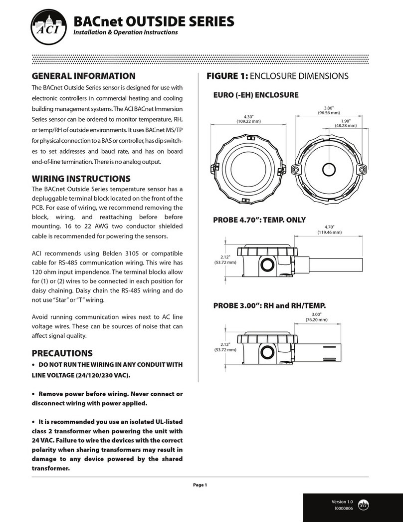
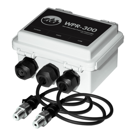
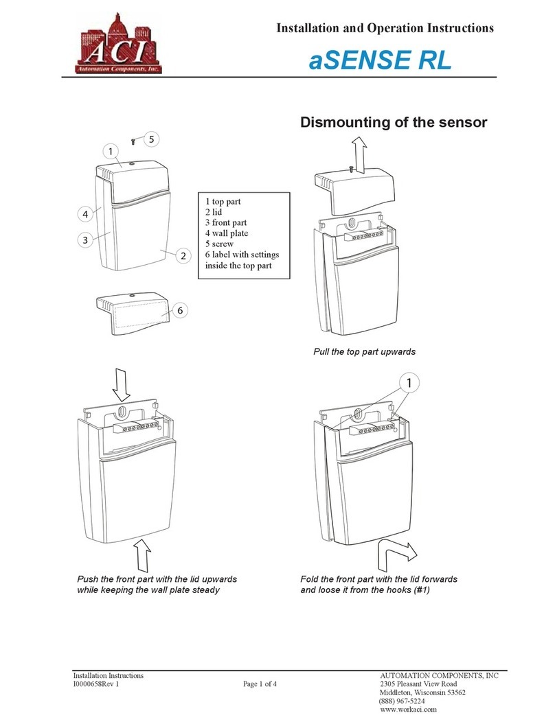
  9. aci Room Series Installation instructions

aci Room Series Installation instructions

Automation Components, Inc.
2305 Pleasant View Road | Middleton, WI 53562
Phone: 1-888-967-5224 | Website: workaci.com
Page 1
Version: 8.0
I0000226
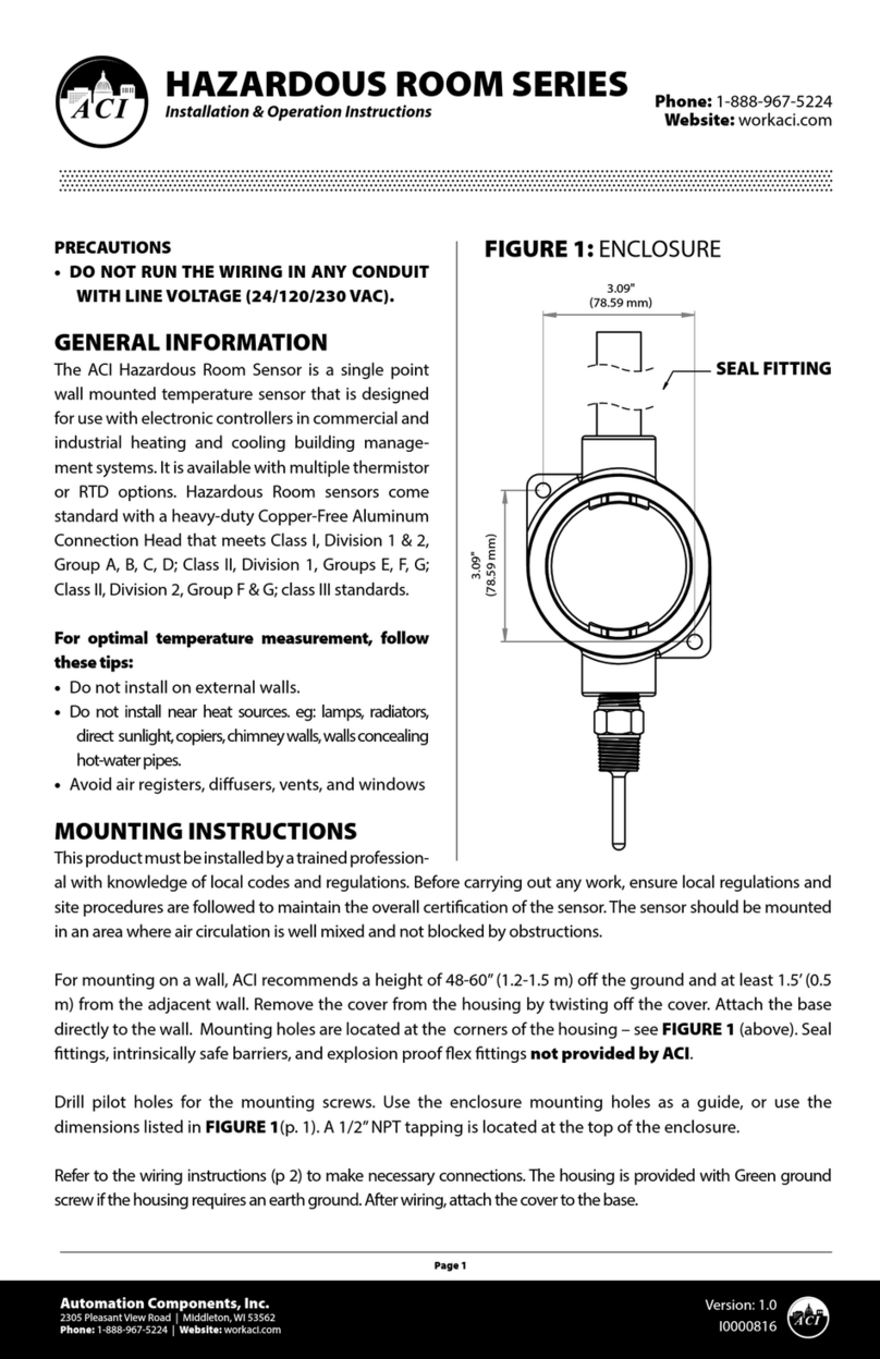
PRECAUTIONS
• DO NOT RUN THE WIRING IN ANY CONDUIT
WITH LINE VOLTAGE (24/120/230 VAC).
GENERAL INFORMATION
The ACI/Enhanced sensor is provided with the
setpoint, override, LED, and communication jack.
The ACI/10K-CP-ALC sensor can have the sensor,
setpoint, and override options.
MOUNTING INSTRUCTIONS
Take care when mounting. Check local code for
mounting height requirements. Typical mounting
heights are 48-60” (1.2-1.5 m) o the ground and at
least 1.5’ (0.5 m) from the adjacent wall. The sensor
should be mounted in an area where air circulation is
well mixed and not blocked by obstructions.
Separate the cover from the base. Attach the base
directly to the wall or to a standard 2” x 4” junction
box using the (2) #6-32 x 1”screws provided.
*Reference FIGURE 2 (next page)
For optimal temperature measurement, follow
these tips:
•Do not install on external walls.
•Avoid air registers, diusers, vents, and windows.
•Avoid conned areas such as shelves, closed
cabinets, closets, and behind curtains.
•Eliminate and seal all wall and conduit penetrations.
Air migration from wall cavities may alter
temperature readings.
•A thermally-insulated backing should be used when
tting to solid walls (concrete, steel, etc.). ACI part:
A/ROOM-FOAM-PAD
•Do not install near heat sources, eg: lamps,
radiators, direct sunlight, copiers, chimney walls,
walls concealing hot-water pipes.
Refer to the Wiring Instructions (p. 2-3) to make
necessary connections. Tighten the cover down,
using the (2) 1/16” Allen screws located in the
bottom of the housing. A 1/16”Hex driver is needed
to secure the cover to the base.
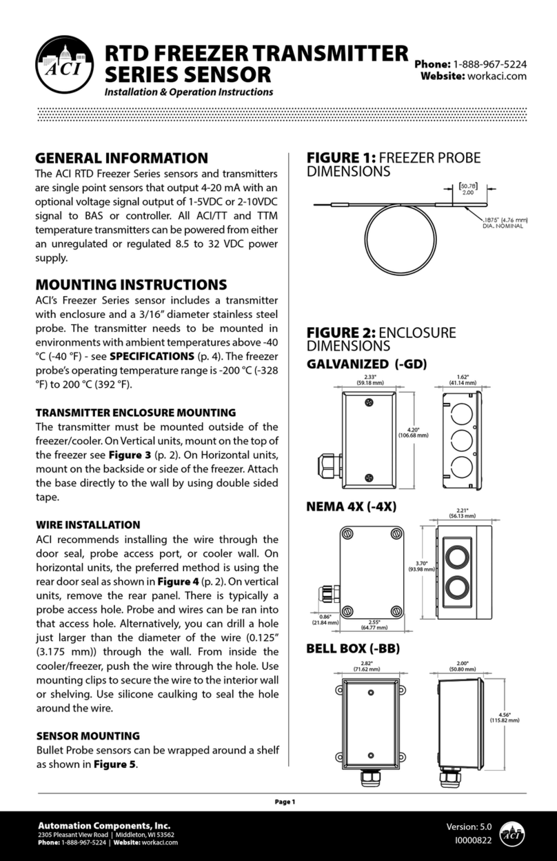
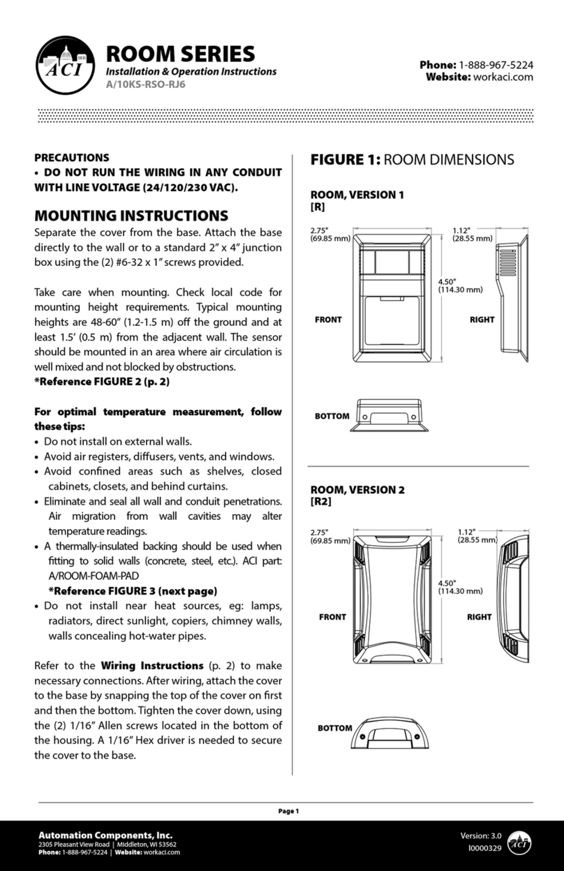
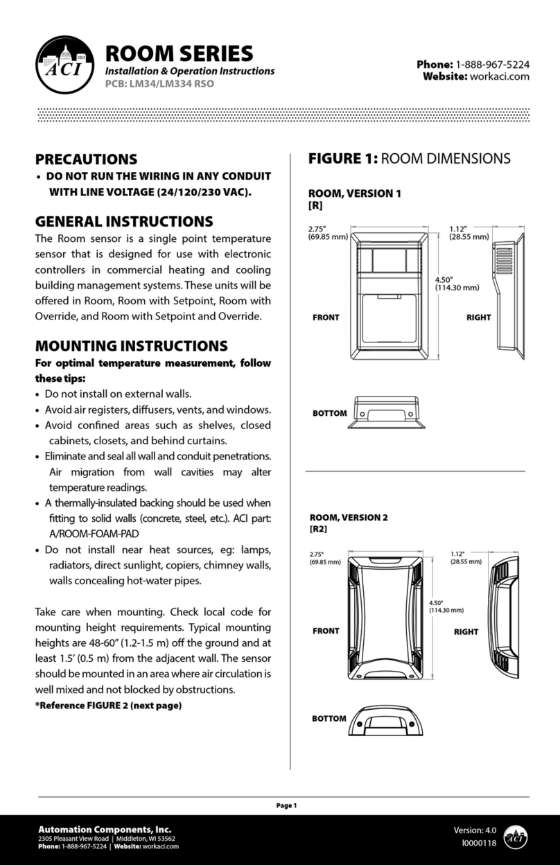
2.75"
(69.85 mm)
2.75"
(69.85 mm)
1.12"
(28.55 mm)
1.12"
(28.55 mm)
4.50"
(114.30 mm)
ROOM, VERSION 1
[R]
ROOM, VERSION 2
[R2]
FRONT
BOTTOM
RIGHT
FRONT
BOTTOM
RIGHT
4.50"
(114.30 mm)
FIGURE 1: ROOM DIMENSIONS
ROOM SERIES
Installation & Operation Instructions
PCB: ENHANCED
Phone: 1-888-967-5224
Website: workaci.com
48"-60"
(1.2-1.5 m)
OPTIONAL INSULATING GASKET
BACKPLATE
MOUNTING SCREWS
(#6-32 x 1”)
CIRCUIT BOARD
COVER
FIGURE 3: LAYOUT
FIGURE 2: MOUNTING
Automation Components, Inc.
2305 Pleasant View Road | Middleton, WI 53562
Phone: 1-888-967-5224 | Website: workaci.com
Page 2
Version: 8.0
I0000226
WIRING INSTRUCTIONS
ACI recommends 16 to 26 AWG twisted pair
wires or shielded cable for all sensors. Signal
wiring must be run separate from low and
high voltage wires (24/120/230 VAC). All ACI
thermistors are both non-polarity and
non-position sensitive. All thermistor type
room units are supplied with a two-pole
terminal block. The number of wires needed
depends on the application. All wiring must
comply with all local and National Electric
Codes. After wiring, attach the cover to the
base by snapping the top of the cover on rst
and then the bottom.
“AFTER HOURS”
NORMALLY-OPEN
OVERRIDE SWITCH
ENHANCED
CONNECTOR
LED
SETPOINT ADJUSTMENT
POTENTIOMETER
THERMISTOR
WHTBLUGRN
RED ORGBLK BRN YEL
TERMINAL
BLOCKS
TABLE 1: ACI/ENHANCED
SENSOR
TERMINAL
1
2
3
4
5
6
7
8
T-LINE
TERMINAL
1
2
3
4
5
6
7
8
WIRE COLOR
Black
Brown
Red
Orange
Yellow
Green
Blue
White
FUNCTION
Ground
Thermistor Input
Switch Input
RSZ+ Input
+ Comm
- Comm
+5 VDC
Relay Control
TABLE 2: ACI/10K-CP-ALC
SENSOR
TERMINAL
1
2
3
FUNCTION
Common
Sensor
Setpoint/Override
WIRING INSTRUCTIONS (Continued)
Note: When using a shielded cable, be sure to connect
only (1) end of the shield to ground at the controller.
Connecting both ends of the shield to ground may cause
a ground loop. When removing the shield from the sensor
end, make sure to properly trim the shield to prevent any
chance of shorting.
WARRANTY
The ACI Room Series temperature sensors are covered by ACI’s Five (5)Year Limited Warranty, which is located in
the front of ACI’S SENSORS & TRANSMITTERS CATALOG or can be found on ACI’s website: www.workaci.com.
W.E.E.E. DIRECTIVE
At the end of their useful life the packaging and product should be disposed of via a suitable recycling
centre. Do not dispose of with household waste. Do not burn.
PRODUCT SPECIFICATIONS
TROUBLESHOOTING
Automation Components, Inc.
2305 Pleasant View Road | Middleton, WI 53562
Phone: 1-888-967-5224 | Website: workaci.com
Page 3
Version: 8.0
I0000226
SETPOINT CONTROL
Adjust slider at bottom of housing for set point control. Slide to right to increase set point temperature. Slide to
left to decrease temperature control.
PROBLEM
Sensor reading is incorrect
Sensor reads infinity/very high resistance
Sensor reads low resistance
Erratic readings
SOLUTION(S)
•Verify sensor wiring to controller is not damaged and has continuity
•Verify sensor or wires are not shorted together
•Verify controller is setup for correct sensor curve
•Disconnect wires from sensor terminal block, tighten terminal block
screws down, and take a resistance (ohm) reading with a multimeter
•Compare the resistance reading to theTemperature Vs Resistance
Curves online: http://www.workaci.com/content/thermistor-curves-0
•Verify proper mounting location to conrm no external factors are
aecting reading
•Sensor or wires are open
•Sensor or wires are shorted together
•Condensation on PCB board
•Bad wire connections
A/CP (Type II): 10 KΩ nominal
All Else: +/- 0.2 °C (+/- 0.36 °F)
One
1/16”Allen screws (2 qty) / 1/16”Hex Driver
“Dry Contact”Closure (Separate Input)
1.5 to 50 °C (35 to 122 °F) | -40 to 65 °C (-40 to 149 °F)
10 to 95% RH, non-condensing
Screw Terminal Blocks (Non-Polarity Sensitive)
16 (1.31 mm²) to 26 AWG (0.129 mm²)
0.5 Nm (Minimum); 0.6 Nm (Maximum)
“R2” Enclosure: ABS Plastic | White, UL94-HB
“R” Enclosure: ABS Plastic | Beige UL94-HB
SENSOR NON-SPECIFIC INFORMATION
Number Temperature Sensing Points:
Housing Screw Size / Drive Size:
Override Option:
Operating | Storage Temperature Range:
Operating Humidity Range:
Connections / Wire Size:
Terminal Block Torque Rating:
Enclosure Material | Color:
THERMISTOR
Sensor Output @ 25 °C (77 °F):
Accuracy @ 0-70 °C (32 - 158 °F):
Automation Components, Inc.
2305 Pleasant View Road
Middleton, WI 53562
Phone: 1-888-967-5224
Website: workaci.com
Page 4
Automation Components, Inc.
2305 Pleasant View Road | Middleton, WI 53562
Phone: 1-888-967-5224 | Website: workaci.com
Version: 8.0
I0000226

This manual suits for next models

1

Other aci Accessories manuals

aci LM34 RSO Installation instructions

aci

aci LM34 RSO Installation instructions

aci HAZARDOUS ROOM Series Installation instructions

aci

aci HAZARDOUS ROOM Series Installation instructions

aci A/CTA2-5 User manual

aci

aci A/CTA2-5 User manual

aci TUCH2 User manual

aci

aci TUCH2 User manual

aci BACnet / Modbus IMMERSION Series Installation instructions

aci

aci BACnet / Modbus IMMERSION Series Installation instructions

aci TUCH2 Installation instructions

aci

aci TUCH2 Installation instructions

aci A/CS2 User manual

aci

aci A/CS2 User manual

aci ROOM Series Installation instructions

aci

aci ROOM Series Installation instructions

aci ACCESS series Installation instructions

aci

aci ACCESS series Installation instructions

aci ACCESS series Installation instructions

aci

aci ACCESS series Installation instructions

aci ROOM Series Installation instructions

aci

aci ROOM Series Installation instructions

aci WPR2-300 Series User manual

aci

aci WPR2-300 Series User manual

aci DRN3.1 User manual

aci

aci DRN3.1 User manual

aci A/SCTA Series Installation instructions

aci

aci A/SCTA Series Installation instructions

aci A/ASCS User manual

aci

aci A/ASCS User manual

aci RTD Freezer Series User manual

aci

aci RTD Freezer Series User manual

aci A/SCTE-50 User manual

aci

aci A/SCTE-50 User manual

aci A/CTE-50 User manual

aci

aci A/CTE-50 User manual

aci HAZARDOUS ROOM Series Installation instructions

aci

aci HAZARDOUS ROOM Series Installation instructions

aci A/CTE2 Series Configuration guide

aci

aci A/CTE2 Series Configuration guide

aci TUCH2 User manual

aci

aci TUCH2 User manual

aci DT2650 Installation instructions

aci

aci DT2650 Installation instructions

aci A/CTA2 Series Installation instructions

aci

aci A/CTA2 Series Installation instructions

aci BACnet Outside Series Installation instructions

aci

aci BACnet Outside Series Installation instructions

Popular Accessories manuals by other brands

Gigabyte 3D Cooler Pro installation guide

Gigabyte

Gigabyte 3D Cooler Pro installation guide

Klarstein 10000164 manual

Klarstein

Klarstein 10000164 manual

HOME8 WTS3100 user manual

HOME8

HOME8 WTS3100 user manual

Anywire AnyWireASLINK BS-K5217-M 1K Series Product guide

Anywire

Anywire AnyWireASLINK BS-K5217-M 1K Series Product guide

Conrad Universal lighter with LED Instructions for use

Conrad

Conrad Universal lighter with LED Instructions for use

Watercool HEATKILLER GPU-X3 GTX480 Assembly guide

Watercool

Watercool HEATKILLER GPU-X3 GTX480 Assembly guide

Nice HySecurity EMX NIR-50-325 PhotoEye Installation and programming instructions

Nice

Nice HySecurity EMX NIR-50-325 PhotoEye Installation and programming instructions

Keating Of Chicago Instant Recovery 004341 Mounting instructions

Keating Of Chicago

Keating Of Chicago Instant Recovery 004341 Mounting instructions

Emerson Rosemount 214C quick start guide

Emerson

Emerson Rosemount 214C quick start guide

Energenie MiHome Gateway Questions & Answers

Energenie

Energenie MiHome Gateway Questions & Answers

Solera 434730 Installation and owner's manual

Solera

Solera 434730 Installation and owner's manual

Ace Weatherproof Long Range Wireless Chime with Chime Extender... owner's manual

Ace

Ace Weatherproof Long Range Wireless Chime with Chime Extender... owner's manual

Gallet GALCCH 120 instruction manual

Gallet

Gallet GALCCH 120 instruction manual

Sven MP-4017 user manual

Sven

Sven MP-4017 user manual

DIS Sensors QG40N User & Safety Manual

DIS Sensors

DIS Sensors QG40N User & Safety Manual

Audioplex HT-5.1 supplementary guide

Audioplex

Audioplex HT-5.1 supplementary guide

Gin Fuse Tandem Pilot manual

Gin

Gin Fuse Tandem Pilot manual

LEGRAND 0 489 59 manual

LEGRAND

LEGRAND 0 489 59 manual

manuals.online logo
manuals.online logoBrands
  • About & Mission
  • Contact us
  • Privacy Policy
  • Terms and Conditions

Copyright 2025 Manuals.Online. All Rights Reserved.