aci KW1850-P1-D-W User manual

ACI KW1850-P1-D-W
Smart Metering System
User's Manual

II
V: 2.00 Revised: June 2023
www.workaci.com
Copyright © 2021 V1.00
This manual may not be altered or reproduced in whole or in part by any means
without the expressed written consent of Automation Components Inc (ACI).

1
V: 2.00 Revised: June 2023
www.workaci.com
Prior to maintenance and repair, the equipment must be de-energized and grounded. All
maintenance work must be performed by qualied, competent accredited professionals who
have received formal training and have experience with high voltage and current devices.
ACI shall not be responsible or liable for any damages or injuries caused by improper meter
installation and/or operation.
The information contained in this document is believed to be accurate at the time of
publication, however, Automation Components Inc (ACI) assumes no responsibility for any errors
which may appear here and reserves the right to make changes without notice. Please ask the local
representative for latest product specications before ordering.
Please read this manual carefully before installation, operation and maintenance of the
ACI KW1850-P1-D-W Series Power Meter only. The following symbols in this manual are used
to provide warning of danger or risk during the installation and operation of the meters.
Electric Shock Symbol: Carries information about procedures which must be
followed to reduce the risk of electric shock and danger to personal health.
Safety Alert Symbol: Carries information about circumstances which if not
considered may result in injury or death.

2
V: 2.00 Revised: June 2023
www.workaci.com
Table of Contents
Chapter 1 - Introduction............................................................................................................................5
1.1 Introduction to Ethernet.............................................................................................. 6
Chapter 2 - Functional Description of the Ethernet module........................................................7
Chapter 3 - Installation Method..............................................................................................................9
3.1 Denition of RJ45 .......................................................................................................10
Chapter 4 - Initializing the Ethernet Module................................................................................... 11
4.1 Cable ............................................................................................................................12
Chapter 5 - Connection Method.......................................................................................................... 13
5.1 Direct Connect to a Computer ..................................................................................14
5.2 Direct Connect to a Router/Switch ...........................................................................17
5.3 Connect through WiFi ................................................................................................18
5.4 Description of Modbus-TCP Protocol.......................................................................18
5.4.1 Protocol ............................................................................................................18
a. Data Frame Format........................................................................................18
b. Modbus Application Header (MBA Header) Field ......................................19
c. Function Field..................................................................................................19
d. Data Field ........................................................................................................20
5.4.2 Format of communication..............................................................................20
Explanation of frame .........................................................................................20
Chapter 6 - Web Interface Readings and Parameter Settings................................................... 22
6.1 User Access Login.......................................................................................................23
6.2 Dashboard...................................................................................................................24
6.3 Metering web page.....................................................................................................25
6.3.1 Basic Metering .................................................................................................26
6.3.2 Demand ............................................................................................................27
6.3.3 Energy ...............................................................................................................28
6.3.4 Harmonics ........................................................................................................29
6.3.5 I/O......................................................................................................................30
6.4 Logs ..............................................................................................................................31

3
V: 2.00 Revised: June 2023
www.workaci.com
6.4.1 Trend Log..........................................................................................................32
6.4.1.1 Real-Time Parameters...........................................................................33
6.4.1.2 Energy .....................................................................................................34
6.4.2 Data log.............................................................................................................35
6.4.3 Alarm Log .........................................................................................................36
6.4.4 Event Log ..........................................................................................................37
6.5 About ...........................................................................................................................37
6.6 Settings ........................................................................................................................38
6.6.1 Meter.................................................................................................................38
Chapter 7 - Communications................................................................................................................ 39
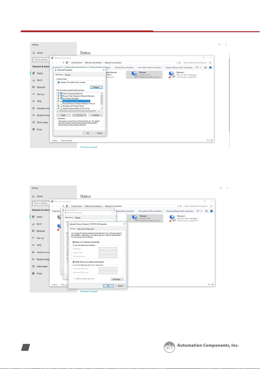
7.1 Network .......................................................................................................................40
7.1.1 Network Settings .............................................................................................40
7.2 Email.............................................................................................................................44
7.3 Time/Date....................................................................................................................48
7.4 Data Log.......................................................................................................................49
7.5 Post Channel ...............................................................................................................52
7.6 AcuCloud......................................................................................................................54
7.7 BACnet/IP.....................................................................................................................56
7.8 SNMP............................................................................................................................57
7.9 MQTT............................................................................................................................58
7.9.1 MQTT General Settings...................................................................................58
7.9.2 MQTT Authentication......................................................................................59
7.9.3 MQTT Encryption.............................................................................................60
7.9.4 Last Will & Testament .....................................................................................60
7.9.5 Topic and Parameter Selection......................................................................61
7.10 Remote Access..........................................................................................................62
Chapter 8 - Management ....................................................................................................................... 64
8.1 Parameter Reset .........................................................................................................65
8.2 Reboot Meter & Communications Module .............................................................65
8.3 Change Password ......................................................................................................66
8.4 SSH ...............................................................................................................................66

4
V: 2.00 Revised: June 2023
www.workaci.com
8.5 Debug Diagnostic .......................................................................................................66
8.6 Diagnostic File .............................................................................................................67
Chapter 9 - Network Diagnostic........................................................................................................... 68
9.1 Network Status ...........................................................................................................69
9.2 Host Lookup ................................................................................................................70
9.3 Connection Test..........................................................................................................70
Chapter - 10 Firmware ............................................................................................................................. 71
10.1 Module Firmware Update .......................................................................................72
10.1.1 Manual Update..............................................................................................73
10.1.2 Remote Update..............................................................................................74
Chapter 11 - Cong Management ...................................................................................................... 77
11.1 Backup Conguration ..............................................................................................79
11.2 Export/Apply Conguration ....................................................................................80
11.3 Import Conguration ...............................................................................................81

ACI KW1850-P1-D-W
Series Power Meter: Web Manual
Chapter 1: Introduction
1.1 Introduction to Ethernet

V: 2.00 Revised: June 2023
6
ACI KW1850-P1-D-W Series Power Meter: Web Manual
www.workaci.com
Chapter 1: Introduction
The ACI KW1850-P1-D-W meter provides a dual Ethernet and WiFi communication channel.
Users will be able to use both Ethernet ports and WiFi simultaneously with dierent networks
and data acquisition systems.
1.1 Introduction to Ethernet
Ethernet was originally developed by Xerox and then further developed by DEC and Intel. This
networking technology uses Carrier Sense Multiple Access with Collision Detection (CDSM/CD)
protocol and provides transmission speeds up to 100Mbps.
Ethernet is not a network but more of a standard. It is the most current communication
standard Local Area Network (LAN). This standard denes the type of cable that is used and
the method of Signal Processing. The ACI KW1850-P1-D-W meter supports two Ethernet
channels.

ACI KW1850-P1-D-W
Series Power Meter: Web Manual
Chapter 2: Functional Description
of the Ethernet Module

V: 2.00 Revised: June 2023
8
ACI KW1850-P1-D-W Series Power Meter: Web Manual
www.workaci.com
Chapter 2:
Functional Description of the Ethernet module
The ACI KW1850-P1-D-W meter supports a wide range of communication protocols. Some of
the more commonly used protocols are briey explained below.
This module supports the Modbus-TCP protocol. When connected to the ACI KW1850-P1-D-W
series meter, it is a slave device that can only respond to queries. The default value for the
Modbus Port is 502. The user-dened range is 2000~5999.
The ACI KW1850-P1-D-W grants users the ability to send emails based on a time interval or
when there is a triggered event using the SMTP protocol. It can send mail from encrypted
servers and servers that use dierent SMTP ports.
The ACI KW1850-P1-D-W supports HTTPS protocol. It is used as an HTTPS server and
where the default value of the protocol port is 443. Using the HTTPS protocol, the ACI
KW1850-P1-D-W can send post requests to both HTTP and HTTPS servers.
The following are all the protocols supported by the AcuRev 2100:
• Modbus TCP
• BACnet-IP
• SNMP V2
• HTTP/HTTPs
• FTP
• sFTP
• Wi-Fi WPA, WPA Enterprise
• NTP
• SMTP
• MQTT

ACI KW1850-P1-D-W
Series Power Meter: Web Manual
Chapter 3: Appearance and Dimensions
Chapter 3: Installation Method
3.1 Denition of RJ45

V: 2.00 Revised: June 2023
10
ACI KW1850-P1-D-W Series Power Meter: Web Manual
www.workaci.com
Chapter 3: Appearance and Dimensions
3.1 Denition of RJ45
The ACI KW1850-P1-D-W uses two standard RJ45 connectors to access the Ethernet network.
The mechanical and electrical characteristics of the connector are consistent with the
requirements of IEC 603-7.
LED_L (Yellow): Displays the speed status. When the LED is on it indicates 100Mpbs, whiles an
o LED represents a speed of 10Mbps.
LED_R (Green): Displays the link and activity status. When the LED is on it indicates the link
status. When the LED is ashing it indicates that there is activity.

ACI KW1850-P1-D-W
Series Power Meter: Web Manual
Chapter 4: Installation
Chapter 4: Initializing the Ethernet Module
4.1 Cable

V: 2.00 Revised: June 2023
12
ACI KW1850-P1-D-W Series Power Meter: Web Manual
www.workaci.com
Chapter 4: Initializing the Ethernet module
The default settings in the ACI KW1850-P1-D-W meter series meter are as follows:
Ethernet 1 (Static IP address)
• IP Address (192.168.1.254)
• Subnet Mask (255.255.255.0)
• Gateway (192.168.1.1)
• DNS Server 1 (8.8.8.8)
• DNS Server 2 (8.8.4.4)
• Modbus Port 502
4.1 Cable
An RJ45 cable is needed to connect the meter to the network.
A shielded twisted pair cable (standard 568A or standard 568B) is recommended as a
reference to the EIA/TIA standard.

ACI KW1850-P1-D-W
Series Power Meter: Web Manual
Chapter 5: LED Description
Chapter 5: Connection Method
5.1 Direct Connect to a Computer
5.2 Direct Connect to a Router/Switch
5.3 Connect through WiFi
5.4 Description of Modbus-TCP Protocol

V: 2.00 Revised: June 2023
14
ACI KW1850-P1-D-W Series Power Meter: Web Manual
www.workaci.com
Chapter 5: Connection Method
5.1 Direct Connect to a Computer
The ACI KW1850-P1-D-W can be connected to a computer using a crossover cable (standard
568A). The ACI KW1850-P1-D-W module supports Modbus-TCP and HTTPS Functions for this
method of connection.
To connect the meter directly to the computer, the computer's IP must be within the same
subnet as the meter's IP address. The following steps outline how to change the computers IP
using a computer running the Windows OS:
• Manually connect the meter via Ethernet cable to the computer
• Right-click on the connection icon
• Select "Open Network Sharing Center"
• Click on Change adapter options

V: 2.00 Revised: June 2023
15
www.workaci.com
• Once there, right-click on the local area connection icon and select properties.
• Select the icon that says Internet Protocol Version 4 TCP/IP
Chapter 5: Connection Method

V: 2.00 Revised: June 2023
16
ACI KW1850-P1-D-W Series Power Meter: Web Manual
www.workaci.com
• The Internet Protocol Version 4 (TCP/IP) Properties box will pop up
• Click on ''Use the following IP address'' and enter an IP number so that the meter and
computer are in the same local network range. For example, if the meter has an IP
address of 192.168.1.254, then the computer must be assigned with an IP 192.168.1.xxx,
where xxx can be any number but cannot be the same as the value the meter has.

V: 2.00 Revised: June 2023
17
www.workaci.com
• Once you have entered in the IP address, press the Tab key on your keyboard until you
hit the bottom and click OK
• Before selecting the OK button make note of the IP address you have assigned to the
meter and then press OK.
NOTE: The meter and computer cannot have the same IP address, they must be dierent.
5.2 Direct Connect to a Router/Switch
The ACI KW1850-P1-D-W can be connected to a router or switch using a patch cable. The DHCP
can be congured to Auto to have the router assign the meter with an IP address or the DHCP
can be congured to Manual to set an IP address and network settings manually.
ACI KW1850-P1-D-W has two Ethernet ports, Ethernet 1 is set to have the static DHCP, and
Ethernet 2 is set to have the dynamic DHCP. Both of the Ethernet ports have the same
functionalities, you can use either of them according to the requirement.
Chapter 5: Connection Method

V: 2.00 Revised: June 2023
18
ACI KW1850-P1-D-W Series Power Meter: Web Manual
www.workaci.com
5.3 Connect through WiFi
The ACI KW1850-P1-D-W can be connected through a WiFi network.
By default, the ACI KW1850-P1-D-W will be in Access Point mode with the default IP address
of 192.168.100.1. Ensure the device connecting to the ACI KW1850-P1-D-W has DHCP enabled
or it should be in the same subnet as the ACI KW1850-P1-D-W. The module will appear in the
WiFi network as AcuRev 2100-WIFI-(serial number of the module) as the SSID or name of the
wireless network. By default, the network key or password will be ''accuenergy''.
• Once connected to the network, open an internet browser and type in the IP address of
the WIFI module: 192.168.100.1
• Log in at Admin access level, using the default password of 'admin'.
5.4 Description of Modbus-TCP Protocol
The Modbus-TCP protocol is used as one of the communication protocols in the
ACI KW1850-P1-D-W. The protocol establishes a master and slave connection in Ethernet. The
master device (client) rst sets up a TCP-IP link with the slave device(server). The master device
then sends a request to the slave device and the slave device in return sends a response to
the master device. The gure below shows how the Modbus-TCP protocol works.
5.4.1 Protocol
a. Data Frame Format
MBAP Header Function Data
7x8 bits 8-bits Nx8 bits
Table of contents
Other aci Measuring Instrument manuals