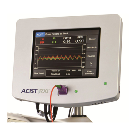
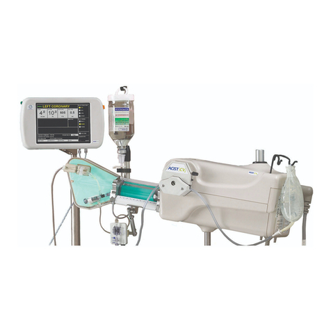
ACIST CVi Installation and operating instructions

Bracco Group
ACIST CVi Contrast Delivery System (including CMS2000 and E2000 Voyager)
User Manual Addendum
901082-001, 03 2012-08

Page ii | ACIST CVi Contrast Delivery System User Manual Addendum 901082-001,03 ENG 2012-08
Proprietary Information Notice
This document contains information proprietary to ACIST Medical Systems, Inc. All rights reserved.
Protected by one or more of the following U.S. patents and international counterparts: 5,515,851; 5,573,515;
5,800,397; 5,916,165; 5,988,587; 6,099,502; 6,221,045; 6,344,030; 6,447,481; 6,626,862; 6,656,157; 6,673,048;
6,746,427; 6,752,789; 6,945,959; 7,101,352; 7,128,729; 7,153,288; 7,169,135;7,267,666;7,357,785;7,389,788;
D404,717. Other U.S. and international patents pending.
No part of this document may be reproduced, transmitted, processed, or recorded by any means or form,
electronic, mechanical, photographic or otherwise, nor be released to any third party without the written
consent of ACIST Medical Systems, Inc.
Copyright © 2010,2011, 2012 ACIST Medical Systems, Inc. All rights reserved.
The written and graphic product descriptions in this manual were eective at the time of printing. ACIST
Medical Systems, Inc. reserves the right to change specications and designs without prior notication.
ACIST, ACIST | CVi, and AngioTouch are registered trademarks of ACIST Medical Systems, Inc. LogiCal, SURE-CAL
and Smiths are registered trademarks of Smiths Group PLC.
Contact Information
USA ACIST Medical Systems, Inc.
7905 Fuller Road
Eden Prairie, MN 55344 USA
Technical Services: 1-888-670-7701
or 952-941-3507
FAX: 952-253-4524
Europe: ACIST Europe BV
II Fiore Building
Renier Nafzgerstraat 114
6221 KL Maastricht
The Netherlands
Technical Services: + 800 22478 387
or +31 43 354 5030
FAX: +31 43 354 5035
Asia ACIST Asia Pte Ltd.
133 New Bridge Road
#20-06/07/08 Chinatown Point
Singapore 059413
Technical Services: + 65 6533 6630
FAX: +65 6533 6631

ACIST CVi Contrast Delivery System User Manual Addendum | Page iii901082-001,03 ENG 2012-08
Contents
Proprietary Information Notice. . . . . . . . . . . . . . . . . . . ii
Contact Information . . . . . . . . . . . . . . . . . . . . . . . ii
1 Introduction 1
Purpose of this Addendum . . . . . . . . . . . . . . . . . . . . . . 1
2 Additional Warnings and Symbol Denitions 3
AdditionalWarnings . . . . . . . . . . . . . . . . . . . . . . . . . 3
Graphical Symbol Denitions . . . . . . . . . . . . . . . . . . . . . 3
3 Saline Pump Setup and Adjustment 7
How to Adjust the Tubing Guides on the Saline Pump . . . . . . . . . . 7
4 Universal Power Supply 9
Optional Universal Power Supply Unit . . . . . . . . . . . . . . . . . 9
Power Supply Specications . . . . . . . . . . . . . . . . . . . . . 9
Power Requirements . . . . . . . . . . . . . . . . . . . . . . . 9
Electrical Leakage . . . . . . . . . . . . . . . . . . . . . . . . 9
Setup Instructions . . . . . . . . . . . . . . . . . . . . . . . . . . 10
Power Supply to Injector Head Power Cable Connection . . . . . . .10
Power Supply to Siemens Scanner Connection. . . . . . . . . . . . 10
Power Supply to Mains Power Connection. . . . . . . . . . . . . . 11
Power Supply Equipotential Cable Connection . . . . . . . . . . . . 11
5 Pedestal Cart 13
Pedestal Cart . . . . . . . . . . . . . . . . . . . . . . . . . . . . 13
Pedestal Cart Specications. . . . . . . . . . . . . . . . . . . . . . 13
How to Mount the Power Supply on the Pedestal Cart . . . . . . . . . . 14
How toTransfer the Injector Head to/from the Pedestal Cart . . . . . . . 15
6 Injection Parameter Ranges and Accuracies 17
7 Supported Imaging Systems 19
8 Hemodynamic Transducer Specications 21
9 EMC Tables 23

Page iv | ACIST CVi Contrast Delivery System User Manual Addendum 901082-001,03 ENG 2012-08
This page intentionally left blank.

ACIST CVi Contrast Delivery System User Manual Addendum | Page 1901082-001,03 ENG 2012-08
Introduction
1 Introduction
e purpose of this addendum for the ACIST CVi User Manual (900468) is
to provide updated information regarding:
• additional warnings and symbol denitions
• adjusting the tubing guides on the saline pump,
• an optional Universal Power Supply unit,
• an optional Pedestal Cart,
• injection parameter ranges and accuracies,
• supported imaging systems,
• hemodynamic transducer specications, and
• electromagnetic environment specications as provided in EMC tables.
Purpose
of this
Addendum

Page 2 | ACIST CVi Contrast Delivery System User Manual Addendum 901082-001,03 ENG 2012-08
Introduction
This page intentionally left blank.

ACIST CVi Contrast Delivery System User Manual Addendum | Page 3901082-001,03 ENG 2012-08
Additional Warnings and Symbol Denitions
2 Additional Warnings and
Symbol Denitions
Additional
Warnings
e following additional warnings refer to hazards that can cause serious
injury or death:
• No modication of this equipment is allowed.
• To avoid the risk of electric shock, this equipment must only be connected
to a supply mains with protective earth.
• e ACIST CVi Contrast Delivery System may only be interfaced with
X-Ray equipment certied IEC 60601-1 2nd or 3rd edition.
• Do not touch the patient while making connections to the injector head
or to the power supply.
• In order to avoid the potential for electric shock to the patient, do not
touch the patient and the X-ray interface connector pins simultaneously.
• In order to avoid the potential for electric shock to the patient, the X-ray
equipment used in conjuction with the ACIST CVi Injector must provide
two means of patient protection.
• In order to meet the debrillator protection specied, the customer must
use ACIST-specied accessories including transducers and adaptor cables.
Symbol Denition
Patient Applied Part, Degree of protection against
electric shock, Type CF debrillation proof
Alternating current.
Equipotentiality
Pushing prohibited
Consult instructions for use.
Graphical
Symbol
Denitions

Page 4 | ACIST CVi Contrast Delivery System User Manual Addendum 901082-001,03 ENG 2012-08
Additional Warnings and Symbol Denitions
Symbol Denition
Do not re-use
Keep dry
Manufacturer.
Date of manufacture.
Serial number.
Catalog number.
CAUTION: Federal law (USA) restricts this device
to sale, distribution, and use by, or on the order of, a
physician.
Dangerous voltage.
Explosion hazard.
Do not tip
European representative.
Contact for service
Graphical
Symbol
Denitions
(continued)

ACIST CVi Contrast Delivery System User Manual Addendum | Page 5901082-001,03 ENG 2012-08
Additional Warnings and Symbol Denitions
Graphical
Symbol
Denitions
(continued)
Symbol Denition
This product should be recycled and not disposed of
as general waste (subject to WEEE annex IV resp.
EN 50419).
In accordance with European Union WEEE
Directive 2002/96/EC, ACIST Europe BV will be fully
responsible for the coordination, logistics, and costs
of the WEEE process.
With respect to electric shock, re, mechanical and
other specied hazards, only in accordance with IEC
60601-1, second and third editions.
Compliance, European directive 93/42/EEC. Medical
Device Directive.
Fragile, handle with care.
Sterilized using ethylene oxide.
IP
21
Environmental enclosure rating, protected against
objects greater than 12 mm and protected against
dripping water, Injector Head.
General warning sign.

Page 6 | ACIST CVi Contrast Delivery System User Manual Addendum 901082-001,03 ENG 2012-08
Additional Warnings and Symbol Denitions
This page intentionally left blank.

ACIST CVi Contrast Delivery System User Manual Addendum | Page 7901082-001,03 ENG 2012-08
Saline Pump Setup and Adjustment
3 Saline Pump Setup and Adjustment
e tubing guides on the saline pump may require adjustment if the tubing
advances through the tubing guides, or if the tubing guide constricts the
tubing and restricts the ow of saline (refer to Troubleshooting section of
ACIST Contrast Delivery System User Manual).
To reduce the need for tubing guide adjustment, the following steps are
recommended in place of steps 20-23 on page 28 of the ACIST Contrast
Delivery System User Manual.
1. Open the saline pump door by rotating the pump handle
counterclockwise.
2. Position both black tubing guides all the way to the top, as shown:
How to Adjust
the Tubing
Guides on the
Saline Pump
Front Tubing Guide in Top Position Rear Tubing Guide in Top Position
3. Place the tubing in the pump. Center the tubing in the pump so that
equal amounts of tubing remain on either side of the pump.
4. Verify that the teeth of the tubing guides are centered over the tubing.
5. Close the saline pump door by rotating the pump handle clockwise,
locking it into position, as shown:
Saline Pump Door Closed

Page 8 | ACIST CVi Contrast Delivery System User Manual Addendum 901082-001,03 ENG 2012-08
Saline Pump Setup and Adjustment
6. Adjust the rear tubing guide downward until it is stopped by the tubing,
as shown:
How to Adjust the Tubing Guides on the Saline Pump (continued)
Move Tubing Guide Downward Tubing Secure in Saline Pump
If the tubing advances through the rear tubing guide, lower the rear
tubing guide one notch.

ACIST CVi Contrast Delivery System User Manual Addendum | Page 9901082-001,03 ENG 2012-08
Universal Power Supply
4 Universal Power Supply
An optional Universal Power Supply unit is available for the CVi Contrast
Delivery System:
Optional
Universal
Power Supply
Unit
Injector Head Power
Cable Connection
Mains Power Cable
Connection
Power Switch
Fuses
Input Cable Connection from
Siemens X-Ray Table
Siemens Output Cable Connection
Power ON Indicator Light
Equipotential Lug
Thumb Screw
Power Requirements
Standard: 100–240 VAC ~, 50–60 Hz, 6.3 A maximum
Power Cord: 12 feet (3.7 meters)
Electrical Leakage
Less than 10 μA (microamperes) for patient connection
Less than 100 μA (microamperes) chassis
e devices comply to EN/IEC 60601-1, second and third editions
Weight
Universal Power Supply: .. .. .. .. .. 12.0 lbs. (5.5 kg.)
Power Supply
Specications

Page 10 | ACIST CVi Contrast Delivery System User Manual Addendum 901082-001,03 ENG 2012-08
Universal Power Supply
Power Supply to Injector Head Power Cable Connection
___________________________________________________________________
WARNING Do not touch the patient while making connections to the injector head
or to the power supply.
___________________________________________________________________
To connect the power cable follow these steps:
1. Connect the end of the Injector Head Power Cable that has a circular
connector with pins to the Power Cable Connection on the Universal
Power Supply.
2. Connect the other end of the Injector Head Power Cable to the
connector located on the back upper right corner of the Injector Head, as
shown:
Power Supply to Siemens Scanner Connection
If connecting the CVi system to a Siemens scanner, follow these steps:
1. Connect cable part number 700709 from the circular Siemens Output
Cable Connection on the Universal Power Supply to the connector on
the lower left corner of the injector head, as shown:
2. Connect cable part number 300864 (a 37-pin connector) from the
Siemens scanner to the Universal Power Supply.
Setup
Instructions
Input Cable Connection from
Siemens X-Ray Table

ACIST CVi Contrast Delivery System User Manual Addendum | Page 11901082-001,03 ENG 2012-08
Universal Power Supply
Power Supply to Mains Power Connection
Connect the AC line power cable to the power entry module on the
power supply. e appropriate medical grade power cable is supplied with
the ACIST injection system. is cable may only be substituted with an
equivalent medical-grade power cable. e power supply must be positioned
to provide easy access to either or both ends of the line power cable for
disconnection from mains power.
Note: On systems interfacing to Philips or Siemens x-ray systems, the power cord is
part of the imaging system interface cord.
Power Supply Equipotential Cable Connection
In order to prevent voltage dierential between medical equipment, an
equipotential cable may be required. Ground equalization can be established
by connecting the equipotential cable to either the equipotential lug (A) or the
thumb screw (B) on the power supply.
A B
e other end of the equipotential cable must be attached to the appropriate
location on the patient table. Both connections on the power supply are in
compliance with IEC60601-1 clause 8.6.10.
Mains Power Cable Connection
Thumb Screw
Equipotential
Lug

Page 12 | ACIST CVi Contrast Delivery System User Manual Addendum 901082-001,03 ENG 2012-08
Universal Power Supply
This page intentionally left blank.

ACIST CVi Contrast Delivery System User Manual Addendum | Page 13901082-001,03 ENG 2012-08
Pedestal Cart
5 Pedestal Cart
A Pedestal Cart for the CVi Contrast Delivery System (illustrated below) is
available in some world-wide markets.
Pedestal
Cart
is section provides:
• Pedestal Cart specications;
• Universal power supply mounting instructions; and
• Injector Head cart/bed rail transferring instructions.
Pedestal Cart
Specications
Wheelbase footprint: 21 in x 25 in (53.3 cm x 63.5 cm)
Height: 36 in (91.4 cm)
Weight: 22.0 lbs (9.98 kg)

Page 14 | ACIST CVi Contrast Delivery System User Manual Addendum 901082-001,03 ENG 2012-08
Pedestal Cart
e power supply mounting bracket on the cart functions like a vice. e
locking handle on the bracket enables you to adjust the bracket width to
easily insert the power supply’s mounting hardware.To mount the power
supply on the cart, do the following:
How to Mount
the Power
Supply on the
Pedestal Cart 1. Align the power supply
mounting bracket with the
bracket on the cart and place the
power supply in the bracket.
2. Tilt the power supply toward
the cart pedestal to engage the
bracket on the power supply with
the bracket on the cart.
3. Slide the power supply toward
the cart bracket locking handle.
4. Locate the pin on the cart’s
mounting bracket and the
corresponding hole on the power
supply bracket.
5. Align the pin of the cart’s
mounting bracket to the hole on
the power supply bracket.
6. Engage lock handle on the cart
bracket and tighten clockwise.
Make sure the power supply is
locked and secure.
NOTE: You can re-position the handle
by pulling it away from the
cart and then resetting its
orientation.

ACIST CVi Contrast Delivery System User Manual Addendum | Page 15901082-001,03 ENG 2012-08
Pedestal Cart
1. Align pins on cart and bed
mount.
2. Unlock lock knob (turn knob
counter-clockwise).
3. Release lock knob (push knob
down).
4. Slide injector head across until
injector head mount is fully
transferred onto the desired
mount (bed rail or cart).
5. Engage lock knob (release and
tighten clockwise).
6. Make sure unit is locked and
secure.
How to Transfer
the Injector Head
to/from the
Pedestal Cart
To transfer the injector head from the bed to the cart or from the cart to the
bed, do the following:
NOTE: Unlock the mount during
transfer only.

Page 16 | ACIST CVi Contrast Delivery System User Manual Addendum 901082-001,03 ENG 2012-08
Pedestal Cart
This page intentionally left blank.
Other manuals for CVi
1
Table of contents
Other ACIST Medical Equipment manuals
Popular Medical Equipment manuals by other brands

DENTSPLY
DENTSPLY Trubyte Alma Instructions for use

Medic Therapeutics
Medic Therapeutics YM201 operating instructions

Respironics
Respironics BiPAP Vision Service manual

Squirrel Medical
Squirrel Medical Dormir Digital MRS Instructions for use

Invacare
Invacare APM brochure

BD
BD Microtainer Quikheel quick start guide