ACL OR-MD Series User manual

Madein
Germany
www.orpc.com
User Manual
Revision 4.2c2 (October 2019)
Translated Version: English
Original version: German
ACL Medical Display
Series OR-MD®

1 1General Instructions
2 2Classification and Intended Use
3
3.1
3
5
Setting Up and Starting Up
Connecting the Cables and Other Units
3.2 6Safety Instructions
3.3
3.4
7
8
Electromagnetic Compatibility (EMC)
Graphical Symbols
4 9Operation
4.1 9Operation Panel
5
5.1
10
10
Servicing
Tips for Care and Hygiene
5.2
5.3
11
11
Maintenance Intervals and Wear Parts
Faulty Signals and Alarm Signals
5.4
5.5
12
13
Repairs
Instructions for Transporting ACL Units
5.6 14Environmentally Correct Disposal
6 15Getting in Contact with the Manufacturer
7 15Imprint
8
8.1
16
16
Warranty and Guarantee
The Warranty
8.2
8.3
17
18
The Guarantee
Scope of and Performing Services
8.4
8.5
18
19
The Service Procedure
Disclaimers
8.6
8.7
20
20
Other Services
Applicable Law
9 20Data Protection

1
www.orpc.com
1 General Instructions
Congratulations on purchasing your new ACL OR-MD
®
. You have decided on a state-of-the-art quality product from a
next-generation manufacturer. These instructions will give you a general idea of the steps you have to take for starting
up and operating this display system. Please read it even if you are familiar with operating display systems.
This documentation might contain technical inaccuracies and typographical errors, although its information is updated
and adapted regularly. We have put great efforts into providing you with correct and generally understandable informa-
tion, although the manufacturer cannot assume any liability for any errors that might be here. We reserve ourselves the
right to make changes in or improve the products described and we are particularly grateful for any suggestions for
improvements, indicating any errors and any constructive criticism.
We will use the term “unit” to designate the OR-MD
®
xx model manufactured by ACL GmbH.
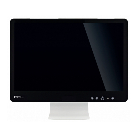
figure: OR-MD®21 with optinal desk stand

2
2 Classification and Intended Use
The unit is designed for displaying data such as patient information inside and outside of operating theaters, intensi-
ve-care wards and similar areas of application. It is intended to assist a signal source device without a display or as its
alternative display.
Following Section 6 of DIN EN 60601-1:2013 the unit is classified as below:
6.2 protective class I unit
6.3 see IP label on your unit, depending on your model IP20 or IP31
An optional IP54 upgrade is available on request for all models.
6.4 This unit is not intended for sterilization.
6.5 It is not intended for operating in an environment with enriched oxygen.
6.6 This unit is suited for permanent operation.
Third-party equipment may be connected in consideration of the restrictions in section 3.1.
The unit is considered as professional ME-Equip according to DIN EN 60601-1-2:2016, paragraph 3.23.
It not is allowed to simultaneously touch the patient and pins of signal input/output components when connecting the
unit to other devices.
The unit can be used within the patient environment.
This unit is not suited to be used in direct contact with the patient.
The patient is not supposed to operate or maintain the unit.
Furthermore, it is not allowed to use this unit in private households.
The unit is not protected against explosions.
Only instructed expert personnel may install, operate and maintain the unit.
There is no information required for activities that should avert damage to humans, animals or environment.

3
www.orpc.com
3 Setting Up and Starting Up
The unit has been cleaned before leaving our production facilities. However, the units are neither sterile nor disinfected
on arrival due to transport conditions and packing. Advices for initial cleaning can be found at section 5.1.
Make sure that the unit and its accessories are complete with the attached delivery note.
Keep the original transport box and packaging in the event that it might have to be transported back (this does not apply
to units with on-site service).
We have used a mounting solution compatible to the VESA-100 standard into the backside of the unit to flexibly and
independently integrate the it into a wide variety of environments and applications. Various manufacturers offer a whole
series of adapters or installation solutions for this. If you want, we can offer you customized installation solutions.
Only use the screws supplied and always use all fastening screws (orange) for correct and save assembly.
The unit may only be operated in an upright position (do not operate it in any direction at an inclination of more than
30° from the norm). The only unit that may be operated with a screen rotated at 90° (portrait mode) are those specially
designated as such (i.e., portrait models). It is not allowed to operate it in impermissible positions (reversed and lying on
its head, back or display) because this may damage the unit.

4
Furthermore, it is necessary to ensure appropriate unit ventilation to protect it from overheating and for reliable and
continuous operation. This is the reason why the unit should not be put in a place or under conditions where it is not
possible to offer sufficient ventilation for the unit’s housing surfaces. Finally, it is not allowed to place or suspend objects
or materials on the unit to prevent heat accumulation or an interruption of the air circulation and to protect the unit’s
mounting from excessive loads.
All service cables should be laid to make sure that nobody steps on them, trips over them or can put heavy objects on
them to prevent the hazard of injury and damage to the unit. Make sure that there is a fixed location and/or stable
suspension.
The industrial protection class of your unit can be upgraded up to IP65. If you have chosen this optional upgrade, one of
the central elements of the IP65-sealing is the cover for the connector interface on the lower side of the unit. Connect all
the required cables to the unit and insert them into the rubber sealings (blue) delivered with the unit. Insert the sealings
into the cover. Finally, fix the cover to the unit’s housing like indicated on the drawings below (orange).
If you have chosen the remote control option for your unit you should ensure to keep the IR-receiver within the opera-
ting panel freely accessible.

5
www.orpc.com
3.1 Connecting the Cables and other Units
Only use the supplied cables.
Start off by connecting the potential equalization cable (special greenish-yellow marking) to ensure a sufficient potential
equalization between the unit and the user. The unit should not be operated in medical areas without connecting up
potential equalization.
Check to see whether your power grid has the correct voltage and frequency before connecting the unit to the mains
(refer to the nameplate on the housing). Afterwards, connect all of the needed cable connectors (such as mains cable,
keyboard, mouse, serial cables, USB and network) to the unit. To prevent the risk of electrical shock, this unit may only
be connected to a supply system with a protective earth. Attaching strain reliefs to the unit is not necessary for the
customer.
If you want to completely disconnect the unit from the power system, turn off the mains switch or pull the power plug
from the outlet or. Never pull on the cable and always hold onto the plug of the cable when disconnecting the power
system connections. Do not set up the unit under conditions that impede the disconnection from the mains.
When creating an electrical connection with other devices or when operating the unit at a mobile multiple outlet,
compliance to the latest version of DIN EN 60601-1 has to be ensured. To maintain conformity in this case so-called
“decoupled connectors” are available optionally. Data can be transferred through this galvanic isolation without any
direct electrical contact. From the electrical point of view the connection of medical equipment on these decoupled
connectors is admissible.
Furthermore, a functional unit is created by exchanging data with other devices, especially if this functional unit is
intended to be used for medical purpose (i.e. unit is controlling infusion pumps or applied parts are connected). Validity
of any assured properties nor conformity to standards for the unit cannot be expanded to the newly created functional
unit. Instead, the party which is placing this unit on the market or in the clinical environment is responsible for its
conformity with all applicable standards.
Furthermore, there might be unforeseeable interactions or even malfunctions on one or both units if the unit is connec-
ted to other units.
We would be glad to provide technical support and resolve unanswered questions.
Figure: Example of a connector interface on the lower side of your OR-MD
®
Available connectors will vary depending on the configuration you have chosen for your unit.

6
3.2 Safety Instructions
Please comply with the safety instructions compiled below to prevent fire, electrical shocks, injuries and damage to the
unit.
Protect the unit from exposure to strong infrared radiation like i.e. direct impact of sunlight.
The unit may only be operated under the following ambient conditions:
Store the unit for three hours at the new operating location before commissioning if a difference in temperature of 10°C is
exceeded. The unit might be damaged due to fast changes in temperature (i.e. by condensed water).
Prevent the unit from showing the same screen content over a longer period of time because TFT displays might have
after images due to the image-sticking effect. Use the Display Off function key to turn the display off if you do not use
the unit for a longer period of time (this does not have any impact on the running programs or functions of the unit). A
LED in the operating panel indicates the fact that the display is deactivated. Alternatively a screensaver could be used.
Protect the unit from strong magnetic fields like the field close to a MRI.
Protect the unit from exposure to strong electromagnetic radiation. Operation close to HF surgery equipment is allowed
for units with optional cable cover as long as the minimum distances listed in Abschnitt 3.3 are maintained.
Protect the unit from exposure to strong ionizing radiation like i.e. the radiation at a C-arm on X-ray devices.
Furthermore, the unit shall be protected from strong impacts and ongoing vibrations.
Temperature
Storage
Humidity
Operating
0 to 40°C*1 -10 to 60°C
10 to 90%
non-condensing
Altitude
5 to 70%
non-condensing
0 to 3.048m
0 to 10.000ft
0 to 12.192m
0 to 40.000ft
Pressure 105 to 70kPa 105 to 19kPa

7
www.orpc.com
3.3 Electromagnetic Compatibility (EMC)
Using other cables than the original ones may affect the EMC. It may also affect the compliance of limiting values assured
on delivery.
Mounting the unit close to other electrical devices may cause interference effects on both devices. A sufficient distance or
shielding between these devices shall be ensured.
The unit is intended for use in an electromagnetic environment in which radiated RF disturbances are controlled. The
user of the unit can help to prevent electromagnetic interference by maintaining a minimum distance between portable
mobile RF communications equipment (transmitters) and the unit, according to the maximum output power of the
communications equipment, as shown below.
Output cables, intended for a direct connection to outdoor wiring, are not covered by the assured EMC characteristics of
the unit. Herefore, additional inspections might be necessary.
Voltage fluctuations/flicker emissions
IEC 61000-3-3
complies
Emissions Test Electromagnetic Environment - GuidanceCompliance Level
Group 1 The unit uses RF energy only for is internal function.
Therefore, is RF emissions are very low and are not likely to
cause any interference in nearby electronic equipment.
Class B
Class D The unit is suitable for other use than in domestic
establishments. The unit is suitable to be directly
connected to the public low-voltage power supply network.
RF emissions
CISPR 11
RF emissions CISPR 11
Harmonic emissions
IEC 61000-3-2
For transmitters rated at a maximum output power not listed above, the recommended separation distance (d) in meters
(m) can be determined using the equation applicable to the frequency of the transmitter, where:
- P is the maximum output power rating of the transmitter in watts (W) according to the transmitter manufacturer;
- U1 is the maximum strenght of frequency fields according to IEC 61000-4-6 ist (3V RMS outside the ISM band,
6V RMS in the ISM- and amateur radio band);
- E1 is the maximum strenght of frequency fields according to IEC 61000-4-3.
Note: These guidelines may not apply in all situations. Electromagnetic propagation is affected by absorption and
reflection from structures, objects and people.
0.23
800MHz to 2.7GHz
P
E
d
=1
7
0.74
2.33
7.38
23.33
0.01 0.12 0.12
150kHz to <80MHz
transmitter max. output
in W
separation distance according to frequency of the transmitter
in m
80MHz to <800MHz
P
U
d
=1
5.3
P
E
d
=1
5.3
0.1 0.37 0.37
11.17 1.17
10 3.69 3.69
100 11.67 11.67

8
3.4 Graphical Symbols
The signs and symbols below may have been used on your unit depending upon the equipment furnished on your
product:
Meaning
CE symbol
international protection marking
general mandatory sign
instructions available in the manual
Symbol Source
or
IEC 60529
ISO 7010-M001
ISO 7010-M002
2006/95/EG
Annex III
93/42/EWG
Annex XII
direct current
alternating current
connection to or
disconnection from the mains
protective earth
potential equalization connection
manufacturer
date of manufacturing
WEEE
barcode scanner
IEC 60417-5031
IEC 60417-5032
IEC 60417-5019
IEC 60417-5021
ISO 15223-1
ISO 15223-1
2002/96/EG
Annex IV
-
RFID scanner -
IEC 60417-5007 and IEC 60417-5008
and
do not touch none
MEDICAL - GENERAL MEDICAL EQUIPMENT
AS TO ELECTRICAL SHOCK, FIRE AND MECHANICAL HAZARDS ONLY
IN ACCORDANCE WITH
ANSI/AAMI ES60601-1: A1:2012, C1:2009/(R)2012 und A2:2010/(R)2012,
CSA CAN/CSA-C22.2 NO. 60601-1:14
EAC symbol
Underwriter Laboratories LLC
CU TR 004/2011
E500364
ACL driver set -
This equipment has been tested and found to comply with the
limits for a Class B digital device, pursuant to part 15 of the FCC Rules.
FCC ID: 2AUWB1 47 CFR Part 15

9
www.orpc.com
4 Operation
You can use the Standby button to turn the unit on and off. This does not disconnect the power supply from the mains
though.
Your unit is equipped with a capacitive operating panel. You can simply touch the glass pane above the symbol to trigger
the key. To prevent the panel from trigger events during wipe disinfection you need to hold your finger on a key for at
least 0.3.
4.1 Operating Panel
The unit operates with the operating panel on the front. The key and LED layout varies according to the equipment you
chose for your unit.
The following key functions can be included:
example figure: OR-MD
®
key panel
LED displays
kein Signal
ready to operate
red
green
on
flashing
unit operating
off
unit in standby
not connected to the mains
function keys
turn unit on/off - standby
no separation from the mains
call up the OSD menu
navigate the OSD menu

10
5 Servicing
The unit cannot be sterilized.
5.1 Tips for Care and Hygiene
All kind of wipe disinfectants that are listed below can be used for cleaning the unit. The original list with all active
substances and product names is available on the Website of the “Robert Koch-Institut “with the title “Liste der vom
Robert Koch-Institut geprüften und anerkannten Desinfektionsmittel und –verfahren“ (source: Bundesgesundheitsblatt
12/2013) or from ACL in German.
The active substances in the following table are expected to be harmless for the unit as long as the listed limits are
observed. The table does not represent a medical evaluation of the effectiveness of these substances.
The following detergents and agents are unsuitable for cleaning:
- acetone
- citric acid
- cleaning liquids basing on crude oil like petroleum, turpentine or oil
Using cleaning pads, rough sponges and cloths might damage surfaces and sealing material.
Please make sure that the unit is cleaned and disinfected with an appropriate cleanser every time it is sent back for
repair. If you are not able to do so mark the unit as contaminated and use safety foil to seal it twice.
To ensure the necessary health conditions for our employees we reserve ourselves the right to initiate suitable measures
on contaminated units at your costs or to refuse the unit at all.
100alcohol 360
Active Substance max. Concentration
in %
max. Exposure
in Minutes Example Products
Bacillol®30 Foam
Meliseptol
8biguanide 360 Incidin Plus
10
chlorine, organic or inorganic
substances with active chlorine 360 Incidin perfekt
Optisept
lye Kalkmilch
8per-compounds 360 Incidin active
Terralin PAA
6phenol or phenolic derivates 360 Helipur

11
www.orpc.com
5.2 Maintenance Intervals and Wear Parts
All units are designed for 24/7-operation. This is resulting in highest requirements to components and materials. To
ensure the reliable operation under these harsh conditions we recommend to replace the following components
prophylactically:
Component
no pretreatment requiredPanel
Exchange After Note
30.000 hours of operation
clearly visible abrasion indicates the need to change
the grommets
grommets in
cable cover if necessary
We would be glad to submit an offer for these maintenance tasks.
No consumables are required.
5.3 Faulty Signals and Alarm Signals
Shut the unit down if you discover any mechanical damage to the housing, display or service cables. You should have
service check the unit in this case because operating the unit with damaged components can cause further damage.
Disconnect the unit from the network immediately in the following cases and get in contact with the manufacturer or
authorized service technician:
- unusual odor or smoke
- a high level of heat escaping from the unit
- damage to the power cable or plug
- faulty unit functioning although you followed the operating instructions
- substantial changes in the unit’s behavior that indicate that it needs service
- mechanical damage to the unit or its frontal glass plate (such as due to a fall)
- unusual noises from the unit during operation
The unit does not have an alarm system.
Restart the unit in the following situations and check the environment for strong sources of EMC radiation and for any
non-conformities with the minimum distances from transmitters listed in section 3.3:
- picture interferences
- short sporadic signal loss
- key panel triggered without user interaction

12
5.4 Repairs
Diligent testing of the unit is guaranteed by the manufacturer. He is responsible for safety-related characteristics within
the legal limits only if repairs and modifications are performed by personnel authorized and trained or supervised by ACL
and if the unit and its accessory are used according to the rules of the intended use. Therefore, there are warranty seals
on or in your unit. Once a seal is broken an expiring warranty has to be assumed. Service personnel may be trained and
certified by ACL only.
After being trained by ACL GmbH you can execute the agreed service activities, for example exchanging several compo-
nents, on your own. Please contact the manufacturer at the address in section 6 for training and advisory as well as the
service manual.
Incorrect repairs are a safety risk. You should not apply your own setting or adjusting methods if they do not comply with
the unit’s specifications or use components not supplied or approved by ACL GmbH because that might damage the unit.
Finally, it is not allowed to make any changes or modifications in the unit or take actions to boost performance beyond
the original settings without the manufacturer’s permission.
There is one fuse for every phase of your unit. It’s characteristics are:
Manufacturer
Model
Schurter AG
5x20mm SPT series
Operating Voltage
Ampere Rating
4A
Characteristic
Breaking Capacity
1,5 kA @ 250 VAC
10 kA @ 125 VAC
250 VAC
T
To change a fuse remove the cover (orange) on your mains filter like indicated on the picture. Thereafter, you can remove
and replace your fuse.

13
www.orpc.com
5.5 Instructions for Transporting ACL Units
Please use ACL transport systems only to avoid any damages due to transportation conditions. If you need an appropriate
transport system, we can send you all required materials for your unit at net costs.
Components might be damaged if improper transport systems are used. Therefore, please take care of a careful handling
during loading and transporting processes. Ensure the compliance with the transport conditions described in the unit’s
manual and on the transport label.
Choose the appropriate transport box depending on the model name on the type plate:
OR-MD® 15 to OR-MD® 24 OR-MD® 27 and OR-MD® 32
Remove all cables, mounting systems and other
accessories.
Place the unit between the swing foils. Press both
swing foils onto each other. The unit shall not have any
space to move between the foils.
Place the accessory box on the upper swing foil.
Use a knife to cut down all four carton corners until
the swing foils have no room left for movements inside
the carton.
Close the carton.
Remove all cables, mounting systems and other
accessories.
Attach the airbags to two opposing sides of the unit
and place it in the carton.
The carton shall be fixed with tension straps onto a
pallet in an upright position. Transporting the carton in
a lying position might damage the unit!
The carton must not be larger than the pallet.

14
5.6 Environmentally Correct Disposal
This section applies for returning old electrical and electronic equipment in the countries of the European Union.
Users of electrical and electronic equipment are obliged to collect old equipment separately. Old electrical or electronic
equipment may not be disposed of together with the unsorted domestic refuse (residential waste) because separate
collection is the prerequisite for re-use, recycling and using old electrical or electronic equipment to drive down resource
utilization.
Please get in contact with the manufacturer at the address given in Section 6 or with an authorized disposal company for
returning your old units. We would be glad to advise you as to the options for disposing of your ACL unit.
Return can be refused for old equipment that constitutes a risk to human health or safety due to contamination during
usage.
The Directive of the European Union states that electrical or electronic units designated with one of the symbols below
may not be disposed of with residential waste.
returning batteries:
The directive of the European Union states that batteries designated with one of the symbols below may not be disposed
of with residential waste. The chemical symbol for the heavy metal contained in it is given below the trash dumpster
with batteries containing pollutants.
Cd cadmium
Hg mercury
Pb lead

15
www.orpc.com
6 Getting in Contact with the Manufacturer
You can get in touch with us at the following address:
ACL GmbH
Apelsteinallee 5
04416 Markkleeberg
Germany
phone: +49 (341) 23078 - 0 8 a.m. to 5 p.m. Monday-Friday
fax: +49 (341) 23078 - 99
email: servic[email protected]
website: www.orpc.com
7 Imprint
Copyright
© 2018 ACL GmbH
No part of this manual may be reproduced in any form (printing, photocopy, microfilm or any other process) without the
prior written permission of the manufacturer or processed, copied or disseminated using electronic systems. We reserve
ourselves the right to make modifications in terms of technical progress. All copyrights shall be reserved to ACL GmbH. All
rights reserved.
Editor
ACL GmbH
Apelsteinallee 5
04416 Markkleeberg
Germany
www.orpc.com
Amtsgericht Leipzig, HRB 13844
VAT-ID: DE 191 570 067
Trademarks
The trademarks used are the property of each of their owners.
All rights reserved, in particular for patents, utility models and registered designs. We reserve ourselves the right to
supply options and technical modifications reserved. The designations given in this document can be brands or registe-
red trademarks whose utilization by third parties for their own purposes may infringe upon the rights of the holder.
Product images may differ from the original product.

16
8 Warranty and Guarantee
Thank you for purchasing a quality product from ACL GmbH. We have developed our products to meet high technical and
quality standards. To maintain this quality, there are some assurances that you as a customer are entitled to claim in the
event of material or processing faults in the product you have purchased. We will use the terms guarantee, warranty and
service to describe the differences between those assurances.
“Warranties” correspond with the legal claims on product liability of the country in which you have bought your unit first
from ACL GmbH.
The “guarantee” granted establishes ACL GmbH’s own voluntary obligation as the manufacturer towards first-time
purchasers of new units. This guarantee does not extend to units that are bought as used units.
The term “service” is used through this section to state generally applicable items of information on both, guarantee and
warranty.
You can find the precise type and term of guarantee or warranty for your ACL product in the description on your original
invoice and original delivery note.
You cannot assert any other or more extensive claims from the guarantee than those described here. Regardless of this,
there may be guarantees of ACL sales partners or other third parties along with this manufacturer’s guarantee that you
can also assert against them.
8.1 The Warranty
The warranty period is 24 months and the warranty commences on the day that a customer of ACL purchases the product
for the first time (the date of the original invoice or the date of the original delivery note). Please bear the fact in mind
that you can only assert claims when you submit the original purchase voucher or original delivery note. This is the
reason why you should always store these documents. The unit’s designation and the unit’s serial number have to be
noted on the invoice/delivery note.
If you purchased your unit in one of the countries that the guarantee laws does not have a regulation for, you can see
the type of guarantee and term of the guarantee in the invoice or delivery note from the first-time sale of the product to
a final customer.
Furthermore, you have to assert warranty claims to ACL GmbH or the responsible sales or service partner without delay
after discovering the fault. This manual contains a list of important phone numbers in section 6 and you can also find a
current list of important phone numbers and contact persons on our website at www.or-pc.com.

17
www.orpc.com
8.2 The Guarantee
Finally, there is the possibility of purchasing services from ACL GmbH and its sales partners for an additional price to
expand the scope and term of the guarantee. These are the available types of guarantee:
bring-in guarantee
The customer brings the defective unit to a qualified ACL service point in consultation with ACL GmbH. In the event
bringing the guarantee into operation, ACL GmbH shall pay the costs for the worktime accumulating and the material or
replacement part needed. The transport to the qualified ACL service point and back shall be at the customer’s risk and
expense.
limited bring-in guarantee on components
The scope of the guarantee can differ from that of the product that you purchased the component with on the following
components. You can find any existing restrictions in the term of the guarantee for the following components in the
attached guarantee document or original invoice/original delivery note.
external keyboard, mouse, barcode scanner and other connection parts
storage batteries and USV
installation system, mounting device and trolley
Please bear the fact in mind that there might be a separate guarantee from another manufacturer for some components.
Please do not hesitate to get in contact with the address specified in Section 6 if you have any questions.
guarantee with on-site service
The customer reports a defective unit to ACL GmbH by email or phone. If ACL GmbH cannot correct the malfunction on the
phone, an ACL service partner will repair the fault at the customer’s location.
Please do not hesitate to get in contact with us for questions on the service territory. We have attached a list of phone
numbers to your product and you can also find a current list in internet under www.or-pc.com. In the event bringing the
guarantee into operation, ACL GmbH shall pay the costs for the working time, travel time, any necessary transport and
material or replacement part needed. Beyond this, if the guarantee with on-site services provides for a certain reaction
time, the service partner generally arrives on the customer’s premises in this time.
Any further claims of the party entitled to the guarantee beyond those explicitly specified in these guarantee conditions
shall be ruled out to the extent that ACL GmbH has a mandatory legal obligation or liability pursuant to the applicable
national law. This shall particularly extend to claims to compensation for consequential damage, lost profit, lost data,
lost information or damage due to an interruption to operations.

18
8.3 Scope of and Performing Services
In the absence of other regulations, the service includes all material and processing faults occurring for the specific term
of the guarantee. Maintained services neither extend the guarantee nor warranty period, nor do they set a new period in
motion. The period for installed replacement parts ends with the guarantee or warranty period for the entire unit.
Defects are excluded from the guarantee that result from anything else than proper operation where proper operation
means operating the product under the conditions described in the operating instructions or product documentation. The
guarantee restricts itself to manufacturing the hardware performance features and the state that the original product had
before the defect.
It shall be sufficient that the product affected complied with the test requirements in conformity with ACL's specifications
for the original product in conformity with the product data sheet. ACL GmbH’s service does not constitute restoring
customer data or software.
The Service is done by repair or replacement at ACL GmbH’s choice within the conditions above. Defective components are
replaced with new or as-new components in the event of material and/or processing faults or the entire product may be
replaced with the same or a functionally equivalent product. In any event, the value of the service shall be restricted to
the value of the faulty product.
The defective components removed from a product in the framework of an event bringing the service into operation shall
become the property of ACL GmbH.
Finally, ACL GmbH or authorized service partners shall provide services at the work times set locally that may vary based
upon national or regional customs.
8.4 The Service Procedure
If errors according to section 5.3 have occurred, in case of a complaint, when the unit is damaged or in case of return due
to routine testing or modification we have enabled a process to ensure processing as fast as possible as well as a clearly
identification of your unit.
Please choose one of the following ways establish a contact with us:
1 - Website
Please visit our Website and fulfill the form at the Support/RMA section as completely as possible:
https://www.orpc.com/en/support/
Table of contents
Other ACL Medical Equipment manuals
Popular Medical Equipment manuals by other brands

Dräger
Dräger Perseus A500 Instructions for use

medaxis
medaxis debritom+ Quick Card

Precision Medical
Precision Medical Easy Go Vac PM66 Series user manual

Maquet
Maquet VENTA MULTI CARE 16 operating instructions

Streifeneder
Streifeneder KINEGEN.air instruction manual

Sizewise
Sizewise SW Alternate user manual