ACL OR-PC Series User manual

ALWAYS A STEP AHEAD
Manual
OR-PC® series

EN
Congratulations on purchasing your
new ACL OR-PC®.
Since 1997 ACL develops and manufactures in Germany optimized IT hardware for use in the medi-
cal sector that meets the special requirements in hygiene-critical areas.
Our intelligent solutions set trends and we are always a step ahead of the competition. Those who
use ACL products receive the highest stringent reliability in tough routine operations, outstanding
quality, durability and ergonomics. The pursuit of innovation at the highest technical standards
and the realization of your individual wishes is our incentive to always deliver excellent products.
All ACL OR-PC®have a sturdy aluminum housing, which supports the highest performance require-
ments. Moreover, the material is completely recyclable and can be repeatedly returned for materi-
al recycling without loss of value or quality.
The manufacturing process is environmentally friendly, as our production is powered by our own
solar energy on the way to a climate neutral manufacturing process.
If there is any complaint about this product, our Service Team from ACL will always kindly support
you. We hope you enjoy your new ACL OR-PC®.
Thomas Wollesky
CEO
ALWAYS A STEP AHEAD 1
Table of Contents
1. General notes....................................................................2
2. Classification and intended use ...................................................2
3. Installation and commissioning ...................................................3
3.1 Cable and device connection..........................................................5
3.2 Device environment, safety and handling instructions ...................................6
3.3 Electromagnetic compatibility (EMC)...................................................7
3.4 BIOS ...............................................................................8
3.5 Graphic symbols ....................................................................9
4. Operation ......................................................................10
4.1 Keypad ............................................................................10
5. Maintenance ...................................................................11
5.1 Care and hygiene instructions .......................................................11
5.2 Maintenance intervals and wearing parts .............................................12
5.3 Malfunctions and alarm signals ......................................................12
5.4 In-house repairs....................................................................13
5.5 Transport notes for ACL devices ......................................................14
5.6 Environmentally sound disposal......................................................14
6. Manufacturer contact ...........................................................15
7. Warranty and guarantee.........................................................15
8. Applicable law ..................................................................15
9. Data protection .................................................................15
Documents
Imprint ............................................................................. 16
Test protocols and declaration ofconformity
EN

ALWAYS A STEP AHEAD 32
EN
1. General notes
This manual provides you with an overview of the necessary steps for commissioning and opera-
ting the computer system. Please read them even if you are familiar with the operation of compu-
ter systems.
We will use the term “unit” to designate the OR-PC®xx model manufactured by ACL GmbH. xx is
used to identify the display size between 09 and 55 inches.
2. Classification and intended use
The unit is designed for documenting data such as patient information inside and outside of
operating theaters, intensive-care wards and similar areas of application. It is supporting the local
software environment and it may be part of the IT network.
Following Section 6 of IEC 60601-1:2012 the unit is classified as below:
6.2 protective class I unit
6.3 see IP label on your unit, depending on your model IP20 or IP31
An optional IP65 upgrade is available on request for all models.
6.4 This unit is not intended for sterilization.
6.5 It is not intended for operating in an environment with enriched oxygen.
6.6 This unit is suited for permanent operation.
The unit is considered as professional ME-Equip according to IEC 60601-1-2:2014, paragraph 3.23.
It not is allowed to simultaneously touch the patient and pins of signal input/output components
when connecting the unit to other devices.
The unit can be used within the patient environment.
This unit is not suited to be used in direct contact with the patient.
The patient is not supposed to operate or maintain the unit.
It is not allowed to use this unit in private households.
The unit is not protected against explosions.
Only qualified expert personnel, which is familiar with the unit and its manual, may install, operate
and maintain the unit.
There is no information required for activities that should avoid damage to humans, animals or
environment.
Third-party equipment may be connected in consideration of the restrictions in Section 3.1.
3. Installation and commissioning
The unit was cleaned before leaving our production facilities. However, the units are neither sterile
nor disinfected on arrival due to transport conditions and packing. Advices for initial cleaning can
be found at Section 5.1.
Make sure that the unit and its accessories are complete according to the attached delivery note.
Keep the original transport box and packaging for the event that it might have to be transported
back (this does not apply to units with on-site service).
The integrated VESA-100 interface on the rear can be used to flexibly attach the unit to mounting
solutions and other devices. Various manufacturers offer a whole series of adapters or installation
solutions for this. We would be pleased to offer customized installation solutions on your request.
The unit may only be operated in an upright position (do not operate it in any direction at an
inclination of more than 30° from the norm). The only units that may be operated with a screen
rotated at 90° (portrait mode) are those specially designated as such (i.e., portrait models). It is not
allowed to operate it in impermissible positions (reversed and lying on its head, back or display)
because this may damage the unit.
Only use the screws supplied and always use all fastening screws (orange) for correct and save
assembly.

ALWAYS A STEP AHEAD 54
EN
3.1 Cable and device connection
Use the supplied connection cables only.
Start off by connecting the potential equalization cable (greenish-yellow marking) to ensure a
sufficient potential equalization between the unit and the user. The unit should not be operated in
medical areas without connecting up potential equalization.
Check to see whether your power grid has the correct voltage and frequency before connecting
the unit to the mains (refer to the nameplate on the housing). Afterwards, connect all of the nee-
ded cable connectors (such as mains cable, keyboard, mouse, serial cables, USB and network) to
the unit. To prevent the risk of electrical shock, this unit may only be connected to a supply system
with a protective earth. Attaching strain reliefs to the unit is not necessary for the customer.
If you want to completely disconnect the unit from the power system, turn off the mains switch or
pull the power plug from the outlet. Never pull on the cable and always hold onto the plug of the
cable when disconnecting the power system connections. Do not set up the unit under conditions
that impede the disconnection from the mains.
When creating an electrical connection with other devices or when operating the unit at a mobile
multiple outlet, compliance to the latest version of IEC 60601-1 has to be ensured. To maintain
conformity in this case so-called “decoupled connectors” are available for connections via RJ45,
RS232 or USB optionally. Data can be transferred through this galvanic isolation without any direct
electrical contact. From the electrical point of view the connection of medical equipment on these
decoupled connectors is admissible.
Furthermore, a functional unit is created by exchanging data with other devices, especially if this
functional unit is intended to be used for medical purpose (i.e. unit is controlling infusion pumps
or applied parts are connected). Validity of any assured properties nor conformity to standards
for the unit cannot be expanded to the newly created functional unit. Instead, the party which is
placing this unit on the market or in the clinical environment is responsible for its conformity with
all applicable standards..
There might be unforeseeable interactions or even malfunctions on one or both units if the unit is
connected to other units.
We would be glad to provide technical support and resolve unanswered questions.
Illustration: Example of a connector interface on the lower side of your OR-PC®
Available connectors will vary depending on the configuration you have chosen for your unit.
Furthermore, appropriate ventilation is necessary to protect the unit from overheating and to
ensure reliable and continuous operation. This is the reason why the unit should not be put in a
place or under conditions where it is impossible to offer sufficient ventilation for the unit’s housing
surfaces. Finally, it is not allowed to place or suspend objects or materials on the unit to prevent
heat accumulation or an interruption of the air circulation and to protect the unit’s mounting from
excessive loads.
All service cables should be laid to make sure that nobody steps on them, trips over them or can
put heavy objects on them to prevent the hazard of injury and damage to the unit. Make sure that
there is a fixed location and/or stable suspension.
The industrial protection class of your unit can be upgraded up to IP65. If you have chosen this
optional upgrade, one of the central elements of the IP65-sealing is the cover for the connector
interface on the lower side of the unit. Connect all the required cables to the unit and insert them
into the rubber sealings (blue) delivered with the unit. Insert the sealings into the cover. Finally, fix
the cover to the unit’s housing like indicated on the drawings below (orange).

ALWAYS A STEP AHEAD 76
EN
3.3 Electromagnetic compatibility (EMC)
Using other cables than the original ones may affect the EMC. It may also affect the compliance of
limiting values assured on delivery.
Output cables, intended for a direct connection to outdoor wiring, are not covered by the assured
EMC characteristics of the unit. Therefore, additional inspections might be necessary.
Stacking units or mounting the unit close to other electrical devices may cause interference effects
on both devices. A sufficient distance or shielding between these devices shall be ensured.
The unit is intended for use in an electromagnetic environment in which radiated RF disturbances
are controlled. The user of the unit can help to prevent electromagnetic interference by maintai-
ning a minimum distance between portable mobile RF communications equipment (transmitters)
and the unit, according to the maximum output power of the communications equipment, as
shown below.
Emissions Test Compliance Level Electromagnetic environment - Guidelines
RF emissions CISPR 11 Group 1 The unit uses RF energy only for is internal function.
Therefore, is RF emissions are very low and are not
likely to cause any interference in nearby electronic
equipment.
RF emissions CISPR 11 Class B tested for both environments (IEC 60601-1-2/5.2.1.1)
Harmonic emissions IEC
61000-3-2 Class D The unit is suitable for other use than in domestic
establishments. The unit is suitable to be directly
connected to the public low-voltage power supply
network.
Voltage fluctuations/ flicker
emissions IEC 61000-3-3 complies
Transmitter maximum
output in W Separation distance according to frequency
of the transmitter in m
150 kHz to <80 MHz 80 MHz to <800 MHz 800 MHz to 2.7 GHz
0.01 0.12 0.12 0.23
0.1 0.37 0.37 0.74
1 1.17 1.17 2.33
10 3.69 3.69 7.38
100 11.67 11.67 23.33
For transmitters rated at a maximum output power not listed above, the recommended separation
distance (d) in meters (m) can be determined using the equation applicable to the frequency of the
transmitter, where:
3.2 Device environment, safety and handling instructions
Please comply with the safety instructions compiled below to prevent fire, electrical shocks, inju-
ries and damage to the unit.
Protect the unit from exposure to strong infrared radiation like i.e. direct impact of sunlight.
Protect the unit from strong magnetic fields like the field close to a MRI.
Protect the unit from exposure to strong electromagnetic radiation. Operation close to HF surgery
equipment is allowed for units with optional cable cover as long as the minimum distances listed
in Section 3.3 are maintained.
Protect the unit from exposure to strong ionizing radiation like i.e. the radiation at a C-arm on X-
ray devices.
Furthermore, the unit shall be protected from strong impacts and ongoing vibrations.
The unit may only be operated under the following ambient conditions:
Operation Storage
Temperature 0 to 40 °C*1
32 to 104 °F -10 to 60 °C
14 to 140 °F
Humidity 10 to 90%
non-condensing 5 to 70%
non-condensing
Height 0 to 3.048 m
0 to 10,000 ft 0 to 12.192 m
0 to 40,000 ft
Pressure 105 to 70 kPa 105 to 19 kPa
*1 If you have ordered upgrades for additional cards like i.e. framegrabber cards an operating temperature
of 35°C shall not be exceeded.
Store the unit for three hours at the new operating location before commissioning if a difference
in temperature of 10°C is exceeded. The unit might be damaged due to fast changes in tempera-
ture (i.e. by condensed water).
Prevent the unit from showing the same screen content over a longer period of time because TFT
displays might have after images due to the image-sticking effect.
Use the “Display Off” function key to turn the display off if you do not use the unit for a longer
period of time (this does not have any impact on the running programs or functions of the unit). A
LED in the operating panel indicates the fact that the display is deactivated. Alternatively, a screen-
saver could be used.

ALWAYS A STEP AHEAD 98
EN
3.5 Graphic symbols
These signs and symbols below may have been used on your unit depending upon the configurati-
on of your product:
Symbol Meaning Source
CE symbol 2006/95/EC Annex III or
93/42/EEC Annex XII
www
.ul.com/marks
ULClassified Logo US und CAN
MEDICAL – GENERAL MEDICAL EQUIPMENT
AS TO ELECTRICAL SHOCK, FIRE AND MECHA-
NICAL HAZARDS ONLY IN ACCORDANCE WITH
ANSI/AAMI ES60601-1: A1:2012, C1:2009/I2012
and A2:2010/I2012, CSA CAN/CSA-C22.2 NO.
60601-1:14
Underwriter Laboratories LLC
EAC mark CU TR 004/2011
international protection code IEC 60529
instructions available in the manual ISO 7010-M002
do not open the unit none
direct current IEC 60417-5031
alternating current IEC 60417-5032
and connection to or disconnection from the mains IEC 60417-5007 resp. IEC 60417-5008
protective earth IEC 60417-5019
potential equalization connection IEC 60417-5021
fuse specification EN 60617-2/07-21-01
manufacturer ISO 15223-1
date of manufacturing ISO 15223-1
WEEE 2002/96/EG Annex IV
barcode scanner -
RFID scanner -
• P is the maximum output power rating of the transmitter in watts (W) according to the transmit-
ter manufacturer;
• U1 is the maximum strength of frequency fields according to IEC 61000-4-6 (3V RMS outside the
ISM band, 6V RMS in the ISM- and amateur radio band);
• E1 is the maximum strength of frequency fields according to IEC 61000-4-3.
Note:
These guidelines may not apply in all situations. Electromagnetic propagation is affected by ab-
sorption and reflection from structures, objects and people.
3.4 BIOS
You can call up the BIOS by pressing “Del” during start up. The BIOS settings of the unit are protec-
ted by a password in standard operation to prevent malfunctions from incorrect settings.
BIOS password ex works: asdf9
You can call up the BIOS by pressing “Del” during start up. The BIOS settings of the unit are protec-
ted by a password in standard operation to prevent malfunctions from incorrect settings.

ALWAYS A STEP AHEAD 1110
EN
5. Maintenance
5.1 Care and hygiene instructions
The unit cannot be sterilized.
All kind of wipe disinfectants that are listed below can be used for cleaning the unit. The complete
list with all active substances and product names is available on the Website of the “Robert Koch-
Institut“ with the title “Liste der vom Robert Koch-Institut geprüften und anerkannten Desinfekti-
onsmittel und –verfahren“ (source: Bundesgesundheitsblatt 10/2017) or from ACL in German.
The active substances in the following table are expected to be harmless for the unit as long as the
listed limits are observed. The table does not represent a medical evaluation of the effectiveness
of these substances.
Active substance max. concentration in % max. exposure time in
minutes Example products
Alcohol 100 360 Bacillol® 30 Foam
Meliseptol
Biguanide 8 360 Incidin Plus
Chlorine, organic or
inorganic substances with
active chlorine
10 360 Incidin perfekt
Optisept
lye - - Lime milk
Per-compounds 8 360 Incidin active
Terralin PAA
Phenol or phenol
derivatives 6 360 Helipur
The following detergents and agents are unsuitable for cleaning:
• acetone
• citric acid
• cleaning liquids basing on crude oil like petroleum, turpentine or oil
Using cleaning pads, rough sponges and cloths might damage surfaces and sealing material.
Please make sure that the unit is cleaned and disinfected with an appropriate cleanser every time
it is sent back for repair. If you are not able to do so, mark the unit as contaminated and use safety
foil to seal it twice.
To ensure the necessary health conditions for our employees we reserve ourselves the right to
initiate suitable measures on contaminated units at your costs or to refuse the unit at all.
4. Operation
You can use the Standby button to turn the unit on and off. This function is equivalent to the
soft-start switch of conventional PC’s. This does not disconnect the power supply from the mains
though.
Your unit is equipped with a capacitive operating panel. You can simply touch the glass pane above
the symbol to trigger the key. To prevent the panel from trigger events during wipe disinfection
you need to hold your finger on a key for at least 0.3s.
Input will be confirmed by a short audio signal.
4.1 Keypad
The unit operates with the operating panel on the front. The key and LED layout varies according
to the equipment you chose for your unit.
The following key functions can be included:
Function keys LED indicators
Unit on/off – standby
no separation from the mains LED indicators in the key
panel
Brightness control: brighter Unit disconnected from the
mains
Brightness control: darker Unit in standby
Turn display and touch screen on/off Unit operating
Barcode reader is activated for 10s Access mass storage
Volume regulation: louder min./max. brightness set
Volume regulation: quieter
Illustration: example of a keypad on the OR-PC®

ALWAYS A STEP AHEAD 1312
EN
5.2 Maintenance intervals and wearing parts
All units are designed for 24/7-operation. This results in highest requirements to components and
materials. To ensure the reliable operation under these harsh conditions we recommend to repla-
ce the following components prophylactically:
Component Replacement after Notes
Mass storage 30.000 hours of operation*1 data backup is recommended
Display panel 30.000 hours of operation no pretreatment required
Grommets in cable cover if necessary clearly visible abrasion indicates the need to change the
grommets
*1 The lifetime of your flash memory depends on various external aspects. High ambient temperature, a high storage utili-
zation as well as a large number of writing operations, especially when writing lots of smaller files, will strain your memory
additionally. Depending on your operation environment other intervals might be reasonable. We would be glad to submit
an offer for these maintenance tasks.
No consumables are required.
5.3 Malfunctions and alarm signals
Shut the unit down if you discover any mechanical damage to the housing, display or service
cables. The unit should be checked by a qualified service partner in this case because operating
the unit with damaged components can cause further damage.
Disconnect the unit from the network immediately in the following cases and get in contact with
the manufacturer or authorized service technician:
• unusual odor or smoke
• a high level of heat escaping from the unit
• damage to the power cable or plug
• faulty unit functioning although you followed the operating instructions
• substantial changes in the unit’s behavior that indicate that it needs service
• mechanical damage to the unit or to its frontal glass plate (such as due to a fall)
• unusual noises from the unit during operation
Restart the unit in the following situations and check the environment for strong sources of EMC
radiation and for any non-conformities with the minimum distances from transmitters listed in
Section 3.3:
• picture interferences
• short sporadic signal loss
• key panel triggered without user interaction
The unit does not have an alarm system.
5.4 In-house repairs
Diligent testing of the unit is guaranteed by the manufacturer. He is responsible for safety-related
characteristics within the legal limits only if repairs and modifications are performed by personnel
authorized and trained or supervised by ACL and if the unit and its accessory are used according
to the rules of the intended use. Therefore, there are warranty seals on or in your unit. Once a seal
is broken an expiring warranty has to be assumed. Service personnel may be trained and certified
by ACL only.
The units are designed to enable the customers’ technical personnel that is capable to deal with
electrical installations to exchange the components listed in this section. Other components shall
be exchanged by ACL GmbH or certified service partners only. Please contact the manufacturer at
the address in Section 6 for training and advisory as well as for the service manual.
Incorrect repairs are a safety risk. You should not apply your own setting or adjusting methods
if they do not comply with the unit’s specifications or use components not supplied or approved
by ACL GmbH because that might damage the unit. Finally, it is not allowed to make any changes
or modifications in the unit or take actions to boost performance beyond the original settings
without the manufacturer’s permission.
If you are about to do a fresh installation on your unit due to maintenance or repairs you can find
all necessary drivers after login in with your customer access data on the ACL website. Informati-
on about the required ACL driver set can be found on the side of your unit next to the download
symbol. You can also ask for the correct driver set at the contact data in Section 6 with your units’
serial number.
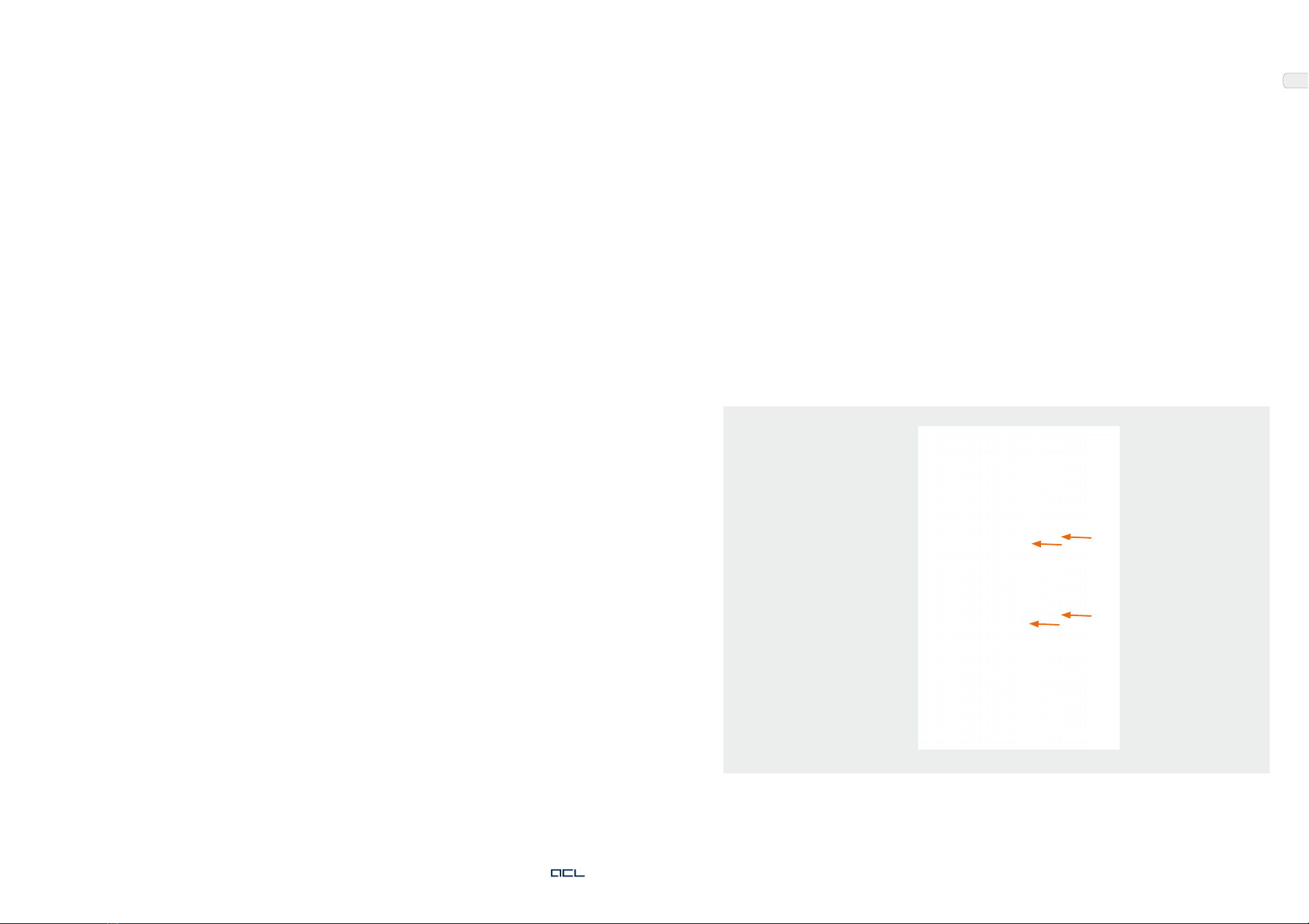
There is one fuse for every phase within the mains filter of your unit. Its characteristics are:
Manufacturer Schurter AG
Model 5X20 mm SPT series
Operating voltage 250V AC
Ampere rating 4A
Characteristic T
Breaking capacity 1.5kA @ 250V AC
10kA @ 125V AC
To change a fuse, remove the cover (orange) on your mains filter like indicated on the picture. The-
reafter, you can remove and replace your fuse.

ALWAYS A STEP AHEAD 1514
EN
6. Manufacturer contact
We are at your disposal at the following address:
ACL GmbH
Apelsteinallee 5
04416 Markkleeberg
Germany
Phone: +49 (341) 23078 - 60 Monday to Friday 8:00 am to 5:00 pm CET
Fax: +49 (341) 23078 - 99
Email: service@acl.de
Internet: www.acl.de/en
7. Warranty and guarantee
We will be happy to provide you with all information on warranty conditions, types of warranty,
repair procedures and exclusions of liability upon request. Our contact details can be found in
Section 6.
8. Applicable law
This guarantee shall be subject to the applicable law in the country where the final customer first
purchased the product from the dealer and it shall be interpreted in agreement with it. The con-
vention on treaties for the international sale of goods shall not apply.
9. Data protection
We would like to point out that data collected from you in the course of processing your order
or preparing an offer will be electronically recorded, processed and evaluated for the purpose
of quality assurance. We assure you that this data will be treated in accordance with the German
General Data Protection Regulation (GDPR).
At your request, we will be happy to inform you free of charge whether and what personal data is
stored about you.
If, in individual cases, you do not wish your personal data to be stored, used and/or transmitted
within the scope of the aforementioned quality assurance measures beyond the immediate war-
ranty processing, you can inform us of this at any time.
For our complete privacy policy, please visit the website mentioned in Section 6.
5.5 Transport notes for ACL devices
To avoid transport damage, please use only the original ACL transport packaging. If you need sui-
table transport packaging, we will be happy to send you suitable materials for your device at short
notice at cost price.
Improper packaging may result in damage to individual components. Therefore, ensure careful
handling during transport and loading operations. Ensure compliance with the transport condi-
tions as described in the device manual and on the package label.
Detailed instructions on how to pack your unit, e.g. for return transport during a repair, can be
found on the ACL website at: https://www.acl.de/en/rma-request
5.6 Environmentally sound disposal
This section applies for returning old electrical and electronic equipment in the countries of the
European Union.
Users of electrical and electronic equipment are obliged to collect old equipment separately. Old
electrical or electronic equipment may not be disposed of together with the unsorted domestic
refuse (residential waste) because separate collection is the prerequisite for re-use, recycling and
using old electrical or electronic equipment to drive down resource utilization.
Please get in contact with the manufacturer at the address given in Section 6 or with an authorized
disposal company for returning your old units. We would be glad to advise you as to the options
for disposing of your ACL unit. Return can be refused for old equipment that constitutes a risk to
human health or safety due to contamination during usage.
The directive of the European Union states that electrical or electronic units designated with one
of the symbols below may not be disposed with residential waste.
Return of batteries:
Batteries marked with one of these symbols must not be disposed of with household waste in ac-
cordance with the EU directive. For batteries containing harmful substances, the chemical symbol
for the heavy metal contained is indicated below the waste garbage can.
Cd Cadmium
Hg Mercury
Pb Lead
For Germany:
The end user is obliged to return defective or used batteries to the distributor or to the
manufacturer's address listed in Section 6.

Imprint
Copyright
© 03/2021 ACL GmbH V5.0
Manual Article Number: 184-00024
No part of these operating instructions may be reproduced in any form (print, photocopy,
microfilm or other processes) or processed, duplicated or distributed using electronic
systems without the prior written consent of the manufacturer. Changes in the sense of
technical improvements are reserved. All copyrights are reserved by ACL GmbH.
Publisher
ACL GmbH
Apelsteinallee 5
04416 Markkleeberg,
Germany
www.acl.de/en
Local court Leipzig, HRB 13844
VAT ID No.: DE 191 570 067
Trademarks
Trademarks used are the property of their respective owners.
All rights reserved, in particular for patents, utility models and design patents, deli-
very possibilities and technical changes. The designations reproduced in this document
may be trademarks or registered trademarks whose use by third parties for their own
purposes may infringe the rights of the owners. Product illustrations may differ from the
original product.
Climate neutral printed on certified FSC® recycling paper in Leipzig, Germany.
16
Imprint
Copyright
© 02/2021 ACL GmbH V1.0
Manual Article Number: 184-00032
No part of these operating instructions may be reproduced in any form (print, photocopy,
microfilm or other processes) or processed, duplicated or distributed using electronic
systems without the prior written consent of the manufacturer. Changes in the sense of
technical improvements are reserved. All copyrights are reserved by ACL GmbH.
Publisher
ACL GmbH
Apelsteinallee 5
04416 Markkleeberg,
Germany
www.acl.de/en
Local court Leipzig, HRB 13844
VAT ID No.: DE 191 570 067
Trademarks
Trademarks used are the property of their respective owners.
All rights reserved, in particular for patents, utility models and design patents, deli-
very possibilities and technical changes. The designations reproduced in this document
may be trademarks or registered trademarks whose use by third parties for their own
purposes may infringe the rights of the owners. Product illustrations may differ from the
original product.
Climate neutral printed on certified FSC® recycling paper in Leipzig, Germany.
336
Here you can find the documents of your device.
BIOS password (default): asdf9
The device drivers and the digital manual can be downloaded
from the login area on the ACL website:
www.acl.de/en
One-time registration required.
Imprint
Copyright
© 02/2021 ACL GmbH V1.0
Manual Article Number: 184-00032
No part of these operating instructions may be reproduced in any form (print, photocopy,
microfilm or other processes) or processed, duplicated or distributed using electronic
systems without the prior written consent of the manufacturer. Changes in the sense of
technical improvements are reserved. All copyrights are reserved by ACL GmbH.
Publisher
ACL GmbH
Apelsteinallee 5
04416 Markkleeberg,
Germany
www.acl.de/en
Local court Leipzig, HRB 13844
VAT ID No.: DE 191 570 067
Trademarks
Trademarks used are the property of their respective owners.
All rights reserved, in particular for patents, utility models and design patents, deli-
very possibilities and technical changes. The designations reproduced in this document
may be trademarks or registered trademarks whose use by third parties for their own
purposes may infringe the rights of the owners. Product illustrations may differ from the
original product.
Climate neutral printed on certified FSC® recycling paper in Leipzig, Germany.
336

www.acl.de
ALWAYS A STEP AHEAD
Table of contents
Other ACL Medical Equipment manuals
Popular Medical Equipment manuals by other brands

Performance Health
Performance Health Performa Combin8 Quattro user manual

GERATHERM
GERATHERM Bodystik Instructions for use

Erbe
Erbe ESM 2 Service manual

Path medical
Path medical SENTIERO DESKTOP SOD100497 quick start guide

FujiFilm
FujiFilm Sonosite PX System Quick reference guide

Avanos
Avanos ON-Q PAIN RELIEF SYSTEM PATIENT GUIDELINES