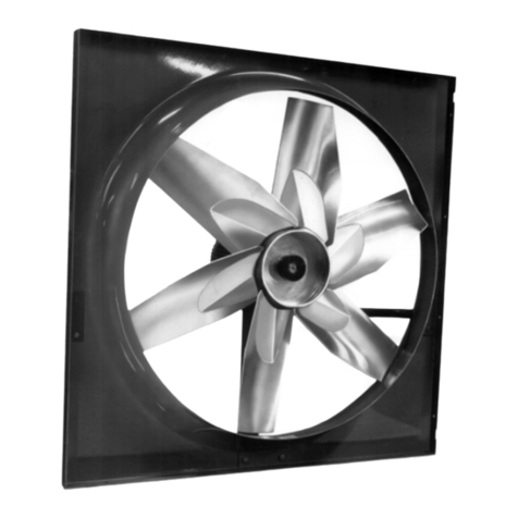
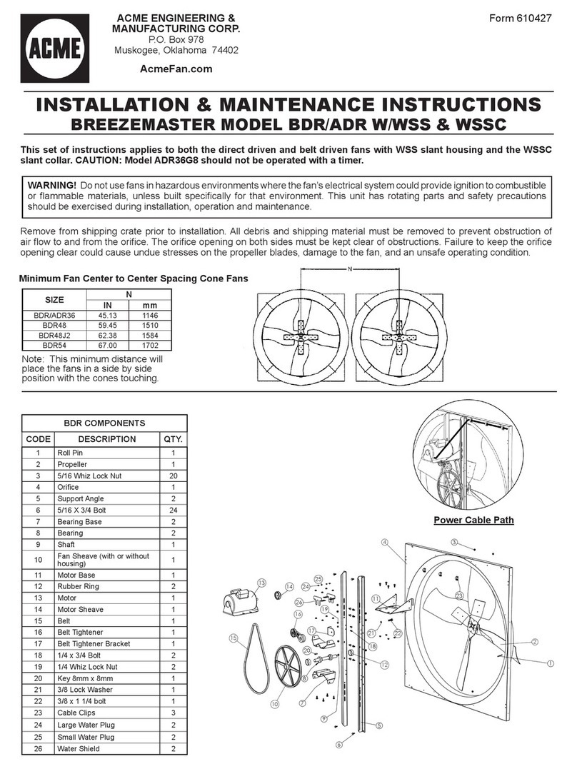
ACME VQL100 User manual

Page 1
MODELS VQL100 • VQL150
VQL200 • VQL250 • VQL300
ACME ENGINEERING & MANUFACTURING CORP.
P.O. Box 978
Muskogee, Oklahoma 74402
!
WARNING
TO REDUCETHE RISK OF FIRE, ELECTRIC SHOCK, OR INJURY
TO PERSONS, OBSERVE THE FOLLOWING:
1. Use this unit only in the manner intended by the manufacturer. If
you have questions, contact the manufacturer at the address or
telephone number listed in the warranty.
2. Before servicing or cleaning unit, switch power off at service panel
and lock the service disconnecting means to prevent power from
being switched on accidentally.When the service disconnecting
means cannot be locked, securely fasten a prominent warning
device, such as a tag, to the service panel.
3. Installation work and electrical wiring must be done by a qualified
person(s) in accordance with all applicable codes and standards,
including fire-rated construction codes and standards.
4. Sufficient air is needed for proper combustion and exhausting of
gases through the flue (chimney) of fuel burning equipment to pre-
vent backdrafting. Follow the heating equipment manufacturer’s
guideline and safety standards such as those published by the
National Fire Protection Association (NFPA), and the American
Society for Heating, Refrigeration and Air Conditioning Engineers
(ASHRAE), and the local code authorities.
5. When cutting or drilling into wall or ceiling, do not damage electri-
cal wiring and other hidden utilities.
6. Ducted fans must always be vented to the outdoors.
7. To reduce the risk of fire, use only metal ductwork.
8. If this unit is to be installed over a tub or shower, it must be marked
as appropriate for the application and be connected to a GFCI
(Ground Fault Interrupter) - protected branch circuit.
9. Never place a switch where it can be reached from a tub or
shower.
10. This unit must be grounded.
CAUTION
1. For general ventilating use only. Do not use to exhaust hazardous
or explosive materials and vapors.
2. To avoid motor bearing damage and noisy and/or unbalanced
impellers, keep drywall spray, construction dust, etc. off power
unit.
3. If ventilator is installed in an unconditioned space (such
as an attic): Surround the ventilator with thermal insulation - to
minimize possible condensation.
4. Please read specification label on product for further information
and requirements.
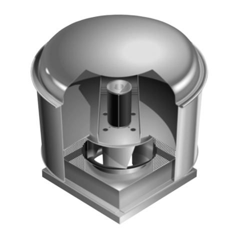
IN-LINE
VENTILATORS
READ AND SAVE THESE INSTRUCTIONS
TABLE OF CONTENTS
This manual is divided into sections as follows:
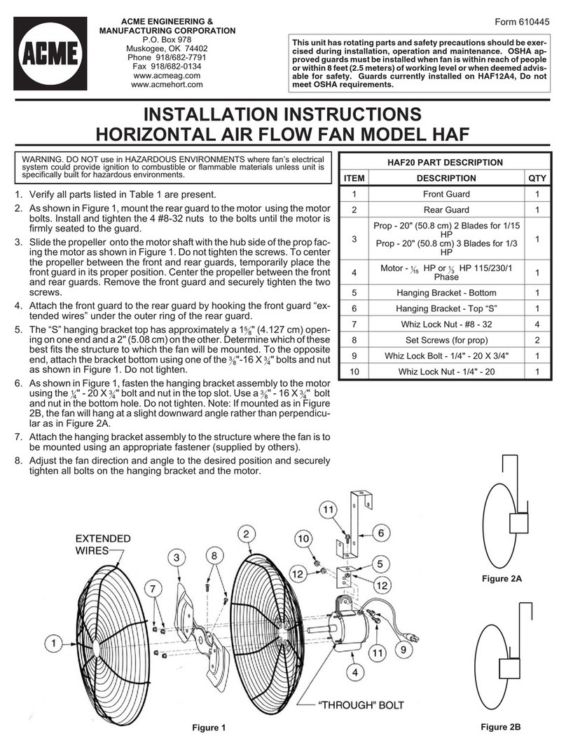
“TYPICAL INSTALLATION”
This section shows a common installation in new and existing,
frame construction.
- Mounting (new construction)
- Mounting (existing construction)
- Wiring
- Ducting (straight through blower discharge)
“MOUNTING OPTIONS”
“WIRING OPTIONS”
-Wiring Plate Position
“DUCTING OPTIONS”
- Blower Discharge Positions
- Ducting (right angle blower discharge)
“USE AND CARE”
“SERVICE PARTS”
“WARRANTY”
Installer: Leave this manual with the homeowner.
Homeowner: Use and Care information on page 3.
Page 1

Page 2
MODELS VQL100 • VQL150
VQL200 • VQL250 • VQL300
ACME ENGINEERING & MANUFACTURING CORP.
P.O. Box 978
Muskogee, Oklahoma 74402
TYPICAL INSTALLATION
MOUNTING (New Frame Construction)
CEILING JOIST
(16” centers shown)
ROUND DUCT*
Factory-shipped unit installed in new construction.
MOUNTING
SCREW
Blower factory-shipped
in straight through
discharge position.
Mounting brackets
factory-shipped in
position for ½” ceil-
ing material.
ADDITIONAL
1½” FRAMING
MOUNTING (Existing Frame Construction)
Factory-shipped unit installed in existing construction.
TYPICAL INSTALLATION
WIRING
WIRING
PLATE
WHITE
TO
WHITE
BLACK
TO
BLACK TOP / BACK
OF HOUSING
120 VAC LINE IN
GROUND TO
WIRING PLATE
ROUND DUCT*
FINISHED
CEILING
MATERIAL
CEILING JOIST
(16” centers
shown)
2 X 4 FRAMING
(wide side down)
MOUNTING
BRACKETS
(Attached to
opposite sides
of housing &
upside-down)
DUCTING (Horizontal blower discharge)
Two ways to connect ductwork to a factory-shipped unit.
Ventilator can be wired from outside of housing.
Use UL approved connectors to wire per local codes.
ROOF CAP
ROUND
ELBOW*
ROUND DUCT*
WALL
CAP
IMPORTANT:
Remove shipping tape from damper
Remove the shipping tape from the damper flap and make sure that
damper flap opens and closes freely inside the ductwork. Use duct
tape to make ductwork connections secure and air-tight.
Remove shipping ring from blower inlet
Remove the shipping ring from the blower inlet before operating
the ventilator.
* VQL100 & VQL150 use 6” round duct.
VQL200, VQL250 & VQL300 use 8” round duct.
* VQL100 & VQL150 use 6” round duct.
VQL200, VQL250 & VQL300 use 8” round duct.

Page 3
MODELS VQL100 • VQL150
VQL200 • VQL250 • VQL300
ACME ENGINEERING & MANUFACTURING CORP.
P.O. Box 978
Muskogee, Oklahoma 74402
12¼"
9
1
/
2
"
to
10
1
/
2
"
ADUSTABLE FOR VARIOUS CEILING THICKNESSES
12¼"
1½"
to
2½"
INSTALLATION FROM ABOVE FINISHED CEILING
MOUNTING OPTIONS
WIRING OPTIONS
DUCTING OPTIONS
12¼"
1
1
/
8
"
MAX.
ADUSTABLE FOR VARIOUS CEILING THICKNESSES
Mounting brackets in
factory-shipped position.
(Outlet parallel to joists.)
(New construction)
12¼"
10 3
/
4
"
to
11 3
/
4
"
INSTALLATION FROM ABOVE FINISHED CEILING
12¼"
INSTALLATION WITH DUCTWORK
RUNNING ACROSS JOISTS
¼-20 hex nuts secure mounting brackets to housing. Loosen and
re-tighten or remove and replace nuts as necessary for desired
mounting bracket position.
Mounting brackets ipped
over and mounted to outlet
sides of housing.
(Outlet parallel to joists.)
(Existing construction)
Mounting brackets mounted
to outlet sides of housing.
(Outlet perpendicular to joists.)
(New construction)
Mounting brackets ipped
over and mounted to top of
sides of housing.
(Outlet parallel to joists.)
(New or existing construction)
12¼"
1
1
/
2
"
to
2
1
/
2
"
ADUSTABLE FOR VARIOUS CEILING THICKNESSES
Mounting brackets ipped
over to give approx. 1”
more clearance.
(Outlet parallel to joists.)
(New construction)
Mounting brackets mounted
to top of sides of housing.
(Outlet parallel to joists.)
(New or existing construction)
BLOWER DISCHARGE POSITIONS
WIRING PLATE
POSITION
Wiring plate mounts to side or top of housing.
HORIZONTAL POWER
CABLE CONNECTION
VERTICAL
POWER CABLE
CONNECTION
Blower and duct connector
in straight through dis-
charge position.
(Factory shipped)
DUCT
CONNECTOR DUCT
CONNECTOR
Blower and duct connector
in right angle discharge
position.
BLOWER
DUCTING (Right angle blower discharge)
Typical ductwork connection to a ventilator converted to
right angle discharge.
ROOF CAP
ROUND
DUCT*
WARNING: To reduce the risk of electric shock,
disconnect from power supply before servicing.
To clean blower assembly: Remove access panel, unplug blower
from housing, remove blower mounting nuts, and carefully remove
blower from housing. Use appropriate vacuum attachment or a soft
cloth and mild soap or detergent to clean blower discharge area and
wheel. DO NOT ALLOW WATER TO ENTER MOTOR. Make sure
blower assembly is completely dry before reinstalling.
Motor is permanently lubricated. Do not oil or disassemble motor.
USE AND CARE
Ventilator is designed for continuous operation. If desired, it may be
controlled using an on/off switch or an electronic, variable speed
control. Follow wiring instructions packed with control, and adhere
to all local and state codes, and the National Electrical Code.
* VQL100 & VQL150 use 6” round duct.
VQL200, VQL250 & VQL300 use 8” round duct.
Change
blower
& duct
connector
positions for
right angle
discharge.
BLOWER

Page 4
MODELS VQL100 • VQL150
VQL200 • VQL250 • VQL300
ACME ENGINEERING & MANUFACTURING CORP.
P.O. Box 978
Muskogee, Oklahoma 74402
SERVICE PARTS SERVICE PARTS
WARRANTY
KEY NO. PART NO. DESCRIPTION
1 97014735 Housing Assembly (VQL100 & VQL150)
97014736 Housing Assembly (VQL200, VQL250, & VQL300)
2 97014728 Mounting Bracket (2 req.)
3 97014760 Damper Assembly (6” dia.)
97014761 Damper Assembly (8” dia.)
4 99390098 Duct Connector (6” dia.)
99390099 Duct Connector (8” dia.)
5 99150415 Screw, 8-18 x ¼ (12 req.)*
6 98005513 Wire Box Cover
7 99400035 Strain Relief Bushing
8 98005512 Wiring Plate
9 99150471 Ground Screw, 10-32 x ½ (2 req.)
10 97014774 Scroll Assembly (VQL100 & VQL150)
97014775 Scroll Assembly (VQL200, VQL250, & VQL300)
11 98009399 Inlet Ring
12 99110805 Blower Wheel
13 99080481 Motor (VQL100)
99080482 Motor (VQL150)
99080483 Motor (VQL200)
99080484 Motor (VQL250)
99080485 Motor (VQL300)
14 99260558 Lock Nut, 8-32 (4 req.)*
15 99250959 Washer (4 req.)*
16 99100491 Grommet (4 req.)
Blower Assembly, Complete
(Includes Key Nos. 10-16)
97014800 (VQL100)
97014801 (VQL150)
97014802 (VQL200)
97014803 (VQL250)
97014804 (VQL300)
17 99260477 Nut, ¼-20 (6 req.)*
18 97006039 Wire Harness
19 98009417 Access Panel
20 99420470 Cover Nut (2 req.)
21 99150472 Cover Mounting Screw (2 req.)
22 99150591 Screw, 10-16 x 7/8 (4 req.)*
Order replacement parts by PART NO. - not by KEY NO.
* Standard hardware - may be purchased locally.
1
2
3
5
6
7
8
9
10
11
12
13
14
15
18
19
20
21
17
16
5
22
22
16
55
5
4
BLOWER AS-
SEMBLY
610602 March 2006 99042746F
LIMITED WARRANTY
WARRANTY AND DISCLAIMER: the Company extends this limited warranty to the original purchaser and warrants that products supplied by the Company, shall be free from original defects in workmanship and materials
for two years from date of shipment (except for the warranty periods noted for products listed below), provided same have been properly handled, stored, installed, serviced, maintained and operated. This warranty shall
not apply to products which have been altered or repaired without the Companys express authorization, or altered or repaired in any way so as, in the Companys judgment, to affect its performance or reliability, nor which
have been improperly installed or subjected to misuse, negligence, or accident, or incorrectly used in combination with other substances. The Purchaser assumes all risks and liability for results of use of all products.
LIMITATION OF REMEDY AND DAMAGES: All claims under this warranty must be made in writing and delivered to P. O. Box 978, Muskogee, Oklahoma, 74402, within 15 days after discovery of the defect and prior to the
expiration of two years from the date of shipment by the Company of the product claimed defective, and Purchaser shall be barred from any remedy if Purchaser fails to make such claim within such period.
Within 30 days after receipt of a timely claim, the Company shall have the option either to inspect the product while in Purchaser’s possession or to request Purchaser to return the product to the Company at Purchaser’s
expense for inspection by the Company. The Company shall replace, or at its option repair, free of charge, any product it determines to be defective, and it shall ship the repaired or replacement product to Purchaser F.O.B.
point of shipment; provided, however, if circumstances are such as in the Companys judgment to prohibit repair or replacement to remedy the warranted defects, the Purchaser’s sole and exclusive remedy shall be a refund
to the Purchaser of any part of the invoice price, paid to the Company, for the defective product or part.
The Company is not responsible for the cost of removal of the defective product or part, damages due to removal, or any expenses incurred in shipping the product or part to or from the Companys plant, or the installation
of the repaired or replaced product or part.
The warranties set forth above do not apply to any components, accessories, parts or attachments manufactured by other manufacturers; such being subject to the manufacturers warranty, if any. To the extent not prohibited
by the manufacturers warranty, the Company shall pass through to Purchaser such manufacturers warranty.
THE COMPANYS WARRANTY IS IN LIEU OF ALL OTHER WARRANTIES, EXPRESS OR IMPLIED, ARISING BY LAW OR OTHERWISE, INCLUDING WITHOUT LIMITATION THE IMPLIEDWARRANTIES OF MERCHANT-
ABILITY AND FITNESS FOR A PARTICULAR PURPOSE, WHICH ARE HEREBY EXPRESSLY DISCLAIMED AND WAIVED. THIS WARRANTY CONSTITUTES THE COMPANYS SOLE AND EXCLUSIVE WARRANTY
FOR DEFECTIVE GOODS AND PURCHASERS SOLE AND EXCLUSIVE REMEDY FOR DEFECTIVE PRODUCTS.
No employee, agent, dealer, or other person is authorized to give any warranties on behalf of the Company or to assume for the Company any other liability in connection with any of its products except in writing and
signed by an officer of the Company.
REPLACEMENT PARTS If replacement parts are ordered, purchaser warrants that the original components in which these replacement parts will be placed are in satisfactory working condition, and when said replacement
parts are installed, the resultant installation will operate in a safe manner, at speeds and temperatures for which the original product was purchased.
TECHNICAL ADVICE AND RECOMMENDATIONS, DISCLAIMER: Notwithstanding any past practice or dealings or any custom of the trade, sales shall not include the furnishing of technical advice or assistance or system
design. Any such assistance shall be at the Companys sole option and may be subject to additional charge.
The Company assumes no obligation or liability on account of any recommendations, opinions or advice as to the choice, installation or use of products. Any such recommendations, opinions or advice are given and shall
be accepted at Purchaser’s and End User’s risk and shall not constitute any warranty or guarantee of such products or their performance.
LIMITATION OF LIABILITY The cumulative liability of the Company to the Purchaser and any other persons for all claims in any way relating to or arising out of the products, including, but not limited to, any cause of action
sounding in contract, tort, or strict liability, shall not exceed the total amount of the purchase price paid for those products which are the subject of any such claim. This limitation of liability is intended to apply without regard
to whether other provisions of this agreement have been breached or have proven ineffective even if the Company has been advised of the possibility of such claims or demands. In no event shall the Company be liable
to the Purchaser or any other person for any loss of profits or any incidental, special, exemplary, or consequential damages for any claims or demands brought by the Purchaser or such other persons.
INDEMNITY The Companys maximum liability to Purchaser and to any end user is as set forth above. The Company makes no warranty to anyone for any products not manufactured by the Company and shall have
no liability for any use or installation of any products (whether manufactured by the Company or other manufacturers) not specifically authorized by this sale. Purchaser acknowledges various warnings by the Company
regarding the products and its installation and use. If the Company incurs any claims, lawsuits, settlements, or expenses (including attorney fees) for any loss, injury, death or property damage including, but not limited to,
claims arising out of the Purchasers or any end users installation or use of the products, the Purchaser shall indemnify and hold the Company harmless.
Acme products are designed and manufactured to provide reliable performance but they are not guaranteed to be 100% free of defects. Even reliable products will experience occasional failures and this possibility should
be recognized by the Purchaser and all End Users. If these products are used in a life support ventilation system where failure could result in loss or injury, the Purchaser and all End Users should provide adequate back-up
ventilation, supplementary natural ventilation or failure alarm system, or acknowledge willingness to accept the risk of such loss or injury.
WARNING DO NOT use in HAZARDOUS ENVIRONMENTS where fans electrical system could provide ignition to combustible or flammable materials unless unit is specifically built for hazardous environments. Comply with
all local and national safety codes including the National Electrical Code (NEC) and National Fire Protection Act (NFPA).
CAUTION Guards must be installed when fan is within reach of personnel or within eight (8) feet (2.5 m) of working level or when deemed advisable for safety.
DISCLAIMER The Company has made a diligent effort to illustrate and describe the products accurately in all Company literature; however such illustrations and descriptions are for the sole purpose of identification and do
not express or imply any warranty.
WARNING
Page 1
ACME ENGINEERING & MANUFACTURING CORP.
P.O. Box 978
Muskogee, Oklahoma 74402 MODELS VQL400 • VQL500 • VQL700
!
WARNING
TO REDUCETHE RISK OF FIRE, ELECTRIC SHOCK, OR INJURY
TO PERSONS, OBSERVE THE FOLLOWING:
1. Use this unit only in the manner intended by the manufacturer. If
you have questions, contact the manufacturer at the address or
telephone number listed in the warranty.
2. Before servicing or cleaning unit, switch power off at service panel
and lock the service disconnecting means to prevent power from
being switched on accidentally. When the service disconnecting
means cannot be locked, securely fasten a prominent warning
device, such as a tag, to the service panel.
3. Installation work and electrical wiring must be done by a qualified
person(s) in accordance with all applicable codes and standards,
including fire-rated construction codes and standards.
4. Sufficient air is needed for proper combustion and exhausting of
gases through the flue (chimney) of fuel burning equipment to pre-
vent backdrafting. Follow the heating equipment manufacturer’s
guideline and safety standards such as those published by the
National Fire Protection Association (NFPA), and the American
Society for Heating, Refrigeration and Air Conditioning Engineers
(ASHRAE), and the local code authorities.
5. When cutting or drilling into wall or ceiling, do not damage electri-
cal wiring and other hidden utilities.
6. Ducted fans must always be vented to the outdoors.
7. To reduce the risk of fire, use only metal ductwork.
8. If this unit is to be installed over a tub or shower, it must be marked
as appropriate for the application and be connected to a GFCI
(Ground Fault Interrupter) - protected branch circuit.
9. Never place a switch where it can be reached from a tub or
shower.
10. This unit must be grounded.
CAUTION
1. For general ventilating use only. Do not use to exhaust hazardous
or explosive materials and vapors.
2. To avoid motor bearing damage and noisy and/or unbalanced
impellers, keep drywall spray, construction dust, etc. off power
unit.
3. If ventilator is installed in an unconditioned space (such
as an attic): Surround the ventilator with thermal insulation - to
minimize possible condensation.
4. Please read specification label on product for further information
and requirements.
IN-LINE
VENTILATORS
READ AND SAVE THESE INSTRUCTIONS
TABLE OF CONTENTS
This manual is divided into sections as follows:
“TYPICAL INSTALLATION”
This section shows a common installation in new and existing,
frame construction.
- Mounting (new construction)
- Mounting (existing construction)
- Wiring
- Ducting (straight-through blower discharge)
“MOUNTING OPTIONS”
“WIRING OPTIONS”
-Wiring Plate Position
“DUCTING OPTIONS”
- Blower Discharge Positions
- Ducting (right angle blower discharge)
“USE AND CARE”
“SERVICE PARTS”
“WARRANTY”
Installer: Leave this manual with the homeowner.
Homeowner: Use and Care information on page 3.
Page 1

MODELS VQL400 • VQL500 • VQL700
Page 2
ACME ENGINEERING & MANUFACTURING CORP.
P.O. Box 978
Muskogee, Oklahoma 74402
TYPICAL INSTALLATION
MOUNTING (New Frame Construction)
CEILING
JOIST
(24” centers
shown)
10” ROUND DUCT
Factory-shipped unit installed in new construction.
MOUNTING
SCREW
Blower factory-shipped
in horizontal
discharge position.
Mounting brackets
factory-shipped in
position for ½” ceil-
ing material.
MOUNTING (Existing Frame Construction)
Factory-shipped unit installed in existing construction.
TYPICAL INSTALLATION
WIRING
WIRING
PLATE
WHITE
TO
WHITE
BLACK
TO
BLACK TOP / BACK
OF HOUSING
120 VAC LINE IN
GROUND TO
WIRING PLATE
10” ROUND
DUCT
FINISHED
CEILING
MATERIAL
CEILING JOIST
(24” centers
shown)
2 X 4 FRAMING
(wide side down)
MOUNTING
BRACKETS
(Attached to
opposite sides
of housing &
upside-down,
so housing is
flush with
finished ceiling)
DUCTING (Straight-through blower discharge)
Two ways to connect ductwork to a factory-shipped unit.
Ventilator can be wired from outside of housing.
Use UL approved connectors to wire per local codes.
ROOF CAP
10”
ROUND
ELBOW
10”
ROUND
DUCT
WALL
CAP
NOTE: Make sure the shipping tape is removed from the damper flap
and that damper flap opens and closes freely inside the ductwork.
Use duct tape to make ductwork connections secure and air-tight.
4½” X 18½”
TO 10” ROUND
TRANSITION
MOUNTING
SCREW
4½” X 18½”
TO 10” ROUND
TRANSITION
4½” X 18½”
TO 10” ROUND
TRANSITION
10” ROUND
DUCT
4½” X 18½”
TO 10” ROUND
TRANSITION
10” ROUND
DUCT
4½” X 18½” TO 10”
ROUND TRANSITION
10”
ROUND
DUCT

Page 3
ACME ENGINEERING & MANUFACTURING CORP.
P.O. Box 978
Muskogee, Oklahoma 74402 MODELS VQL400 • VQL500 • VQL700
ADUSTABLE FOR VARIOUS CEILING THICKNESSES
21½"
9
1
/
2
" to
10
1
/
2
"
21½"
ADUSTABLE FOR VARIOUS CEILING THICKNESSES
10 3
/
4" to
11 3
/
4"
MOUNTING OPTIONS
WIRING OPTIONS
DUCTING OPTIONS
21½"
1
1
/
8
"
MAX.
ADUSTABLE FOR VARIOUS CEILING THICKNESSES
Mounting brackets in
factory-shipped position.
(Outlet parallel to joists.)
(New construction)
12¼"
INSTALLATION WITH DUCTWORK
RUNNING ACROSS JOISTS
¼-20 hex nuts secure mounting brackets to housing. Loosen and
re-tighten or remove and replace nuts as necessary for desired
mounting bracket position.
Mounting brackets mounted
to outlet sides of housing.
(Outlet perpendicular to joists.)
(New construction)
Mounting brackets ipped
over and mounted to top of
sides of housing.
(Outlet parallel to joists.)
(New or existing construction)
1
1
/
2
"
to
2
1
/
2
"
21½"
ADUSTABLE FOR VARIOUS CEILING THICKNESSES
Mounting brackets ipped
over to give approx. 1”
more clearance.
(Outlet parallel to joists.)
(New construction)
Mounting brackets mounted
to top of sides of housing.
(Outlet parallel to joists.)
(New or existing construction)
BLOWER DISCHARGE POSITIONS
WIRING PLATE
POSITION
Wiring plate mounts to side or top of housing.
HORIZONTAL POWER
CABLE CONNECTION
VERTICAL
POWER CABLE
CONNECTION
Blower and duct connector
in straight-through dis-
charge position. (Factory
shipped)
DUCT CONNECTOR
Blower and duct connector
in right angle discharge
position.
BLOWER
Change
blower
& duct
connector
positions for
right angle
discharge.
DUCTING (Right angle blower discharge)
Typical ductwork connection to a ventilator converted to
right angle discharge.
ROOF CAP
10”
ROUND
DUCT
WARNING: To reduce the risk of electric shock,
disconnect from power supply before servicing.
To clean blower assembly: Remove access panel, unplug blower
from housing, remove blower mounting nuts, and carefully remove
blower from housing. Use appropriate vacuum attachment or a soft
cloth and mild soap or detergent to clean blower discharge area and
wheel. DO NOT ALLOW WATER TO ENTER MOTOR. Make sure
blower assembly is completely dry before reinstalling.
Motor is permanently lubricated. Do not oil or disassemble motor.
USE AND CARE
Ventilator is designed for continuous operation. If desired, it may
be controlled using an on/off switch or a solid-state, variable speed
control. Follow wiring instructions packed with control, and adhere
to all local and state codes, and the National Electrical Code.
4½” X 18½”
TO 10” ROUND
TRANSITION
INSTALLATION FROM ABOVE FINISHED CEILING
21½"
1½"
to
2½"
Mounting brackets ipped
over and mounted to outlet
sides of housing.
(Outlet parallel to joists.)
(Existing construction)
DUCT CONNECTOR
BLOWER

MODELS VQL400 • VQL500 • VQL700
Page 4
ACME ENGINEERING & MANUFACTURING CORP.
P.O. Box 978
Muskogee, Oklahoma 74402
SERVICE PARTS SERVICE PARTS
KEY NO. PART NO. DESCRIPTION
1 97014744 Housing Assembly
2 97014728 Mounting Bracket (2 req.)
3 98009449 Duct Connector (2 req.)
4 97014822 Damper Flap Assembly (2 req.)
5 99150415 Screw, 8-18 x ¼ (18 req.)*
6 98005512 Wiring Plate
7 99150471 Ground Screw, 10-32 x ½ (2 req.)
8 98005513 Wire Box Cover
9 99400035 Strain Relief Bushing
10 97006039 Wire Harness
11 99260477 Nut, ¼-20 (12 req.)*
12 97014745 Scroll Assembly (2 req.)
13 99110805 Blower Wheel, (2 req.)
14 98009399 Inlet Ring (2 req.)
15 99080486 Motor (VQL400)
99080487 Motor (VQL500)
99080488 Motor (VQL700)
16 97014794 Motor Mounting Bracket
17 99100497 Rubber Isolator (4 req.)
18 99160380 Screw, 10-24 x 7/8 (4 req.)*
19 99250399 Washer (4 req.)*
20 99260306 Nut, Hex 10-24 (4 req.)*
21 99250254 Washer (4 req.)*
22 93260456 Nut, Hex Flange 3/8-16
23 98009461 Scroll Mounting Channel
--- ------------- Blower Assembly, Complete
(Includes Key Nos. 5 & 11-23)
97014817 (VQL400)
97014819 (VQL500)
97014821 (VQL700)
24 98009464 Access Panel
25 99420470 Access Panel Nut (4 req.)
26 99150472 Access Panel Mounting Screw (4 req.)
27 99150591 Screw, 10-16 x 7/8 (4 req.)
Order replacement parts by PART NO. - not by KEY NO.
* Standard hardware - may be purchased locally.
1
2
3
5
23
13
14
12 12
8
6
9
24
15
7
14
13
16
17
18
19
20
21
22
11
10
26
25
5
5
211
27
4
11
5
11
3
WARRANTY
5
BLOWER
ASSEMBLY
610603 March 2006 99042755F
LIMITED WARRANTY
WARRANTY AND DISCLAIMER: the Company extends this limited warranty to the original purchaser and warrants that products supplied by the Company, shall be free from original defects in workmanship and materials
for two years from date of shipment (except for the warranty periods noted for products listed below), provided same have been properly handled, stored, installed, serviced, maintained and operated. This warranty shall
not apply to products which have been altered or repaired without the Companys express authorization, or altered or repaired in any way so as, in the Companys judgment, to affect its performance or reliability, nor which
have been improperly installed or subjected to misuse, negligence, or accident, or incorrectly used in combination with other substances. The Purchaser assumes all risks and liability for results of use of all products.
LIMITATION OF REMEDY AND DAMAGES: All claims under this warranty must be made in writing and delivered to P. O. Box 978, Muskogee, Oklahoma, 74402, within 15 days after discovery of the defect and prior to the
expiration of two years from the date of shipment by the Company of the product claimed defective, and Purchaser shall be barred from any remedy if Purchaser fails to make such claim within such period.
Within 30 days after receipt of a timely claim, the Company shall have the option either to inspect the product while in Purchaser’s possession or to request Purchaser to return the product to the Company at Purchaser’s
expense for inspection by the Company. The Company shall replace, or at its option repair, free of charge, any product it determines to be defective, and it shall ship the repaired or replacement product to Purchaser F.O.B.
point of shipment; provided, however, if circumstances are such as in the Companys judgment to prohibit repair or replacement to remedy the warranted defects, the Purchaser’s sole and exclusive remedy shall be a refund
to the Purchaser of any part of the invoice price, paid to the Company, for the defective product or part.
The Company is not responsible for the cost of removal of the defective product or part, damages due to removal, or any expenses incurred in shipping the product or part to or from the Companys plant, or the installation
of the repaired or replaced product or part.
The warranties set forth above do not apply to any components, accessories, parts or attachments manufactured by other manufacturers; such being subject to the manufacturers warranty, if any. To the extent not prohibited
by the manufacturers warranty, the Company shall pass through to Purchaser such manufacturers warranty.
THE COMPANYS WARRANTY IS IN LIEU OF ALL OTHER WARRANTIES, EXPRESS OR IMPLIED, ARISING BY LAW OR OTHERWISE, INCLUDING WITHOUT LIMITATION THE IMPLIEDWARRANTIES OF MERCHANT-
ABILITY AND FITNESS FOR A PARTICULAR PURPOSE, WHICH ARE HEREBY EXPRESSLY DISCLAIMED AND WAIVED. THIS WARRANTY CONSTITUTES THE COMPANYS SOLE AND EXCLUSIVE WARRANTY
FOR DEFECTIVE GOODS AND PURCHASERS SOLE AND EXCLUSIVE REMEDY FOR DEFECTIVE PRODUCTS.
No employee, agent, dealer, or other person is authorized to give any warranties on behalf of the Company or to assume for the Company any other liability in connection with any of its products except in writing and
signed by an officer of the Company.
REPLACEMENT PARTS If replacement parts are ordered, purchaser warrants that the original components in which these replacement parts will be placed are in satisfactory working condition, and when said replacement
parts are installed, the resultant installation will operate in a safe manner, at speeds and temperatures for which the original product was purchased.
TECHNICAL ADVICE AND RECOMMENDATIONS, DISCLAIMER: Notwithstanding any past practice or dealings or any custom of the trade, sales shall not include the furnishing of technical advice or assistance or system
design. Any such assistance shall be at the Companys sole option and may be subject to additional charge.
The Company assumes no obligation or liability on account of any recommendations, opinions or advice as to the choice, installation or use of products. Any such recommendations, opinions or advice are given and shall
be accepted at Purchaser’s and End User’s risk and shall not constitute any warranty or guarantee of such products or their performance.
LIMITATION OF LIABILITY The cumulative liability of the Company to the Purchaser and any other persons for all claims in any way relating to or arising out of the products, including, but not limited to, any cause of action
sounding in contract, tort, or strict liability, shall not exceed the total amount of the purchase price paid for those products which are the subject of any such claim. This limitation of liability is intended to apply without regard
to whether other provisions of this agreement have been breached or have proven ineffective even if the Company has been advised of the possibility of such claims or demands. In no event shall the Company be liable
to the Purchaser or any other person for any loss of profits or any incidental, special, exemplary, or consequential damages for any claims or demands brought by the Purchaser or such other persons.
INDEMNITY The Companys maximum liability to Purchaser and to any end user is as set forth above. The Company makes no warranty to anyone for any products not manufactured by the Company and shall have
no liability for any use or installation of any products (whether manufactured by the Company or other manufacturers) not specifically authorized by this sale. Purchaser acknowledges various warnings by the Company
regarding the products and its installation and use. If the Company incurs any claims, lawsuits, settlements, or expenses (including attorney fees) for any loss, injury, death or property damage including, but not limited to,
claims arising out of the Purchasers or any end users installation or use of the products, the Purchaser shall indemnify and hold the Company harmless.
Acme products are designed and manufactured to provide reliable performance but they are not guaranteed to be 100% free of defects. Even reliable products will experience occasional failures and this possibility should
be recognized by the Purchaser and all End Users. If these products are used in a life support ventilation system where failure could result in loss or injury, the Purchaser and all End Users should provide adequate back-up
ventilation, supplementary natural ventilation or failure alarm system, or acknowledge willingness to accept the risk of such loss or injury.
WARNING DO NOT use in HAZARDOUS ENVIRONMENTS where fans electrical system could provide ignition to combustible or flammable materials unless unit is specifically built for hazardous environments. Comply with
all local and national safety codes including the National Electrical Code (NEC) and National Fire Protection Act (NFPA).
CAUTION Guards must be installed when fan is within reach of personnel or within eight (8) feet (2.5 m) of working level or when deemed advisable for safety.
DISCLAIMER The Company has made a diligent effort to illustrate and describe the products accurately in all Company literature; however such illustrations and descriptions are for the sole purpose of identification and do
not express or imply any warranty.
WARNING
Page 1
ACME ENGINEERING & MANUFACTURING CORP.
P.O. Box 978
Muskogee, Oklahoma 74402 MODELS VQL900 • VQL1500
!
WARNING
TO REDUCETHE RISK OF FIRE, ELECTRIC SHOCK, OR INJURY
TO PERSONS, OBSERVE THE FOLLOWING:
1. Use this unit only in the manner intended by the manufacturer. If
you have questions, contact the manufacturer at the address or
telephone number listed in the warranty.
2. Before servicing or cleaning unit, switch power off at service panel
and lock the service disconnecting means to prevent power from
being switched on accidentally. When the service disconnecting
means cannot be locked, securely fasten a prominent warning
device, such as a tag, to the service panel.
3. Installation work and electrical wiring must be done by a qualified
person(s) in accordance with all applicable codes and standards,
including fire-rated construction codes and standards.
4. Sufficient air is needed for proper combustion and exhausting of
gases through the flue (chimney) of fuel burning equipment to pre-
vent backdrafting. Follow the heating equipment manufacturer’s
guideline and safety standards such as those published by the
National Fire Protection Association (NFPA), and the American
Society for Heating, Refrigeration and Air Conditioning Engineers
(ASHRAE), and the local code authorities.
5. When cutting or drilling into wall or ceiling, do not damage electri-
cal wiring and other hidden utilities.
6. Ducted fans must always be vented to the outdoors.
7. To reduce the risk of fire, use only metal ductwork.
8. If this unit is to be installed over a tub or shower, it must be marked
as appropriate for the application and be connected to a GFCI
(Ground Fault Interrupter) - protected branch circuit.
9. Never place a switch where it can be reached from a tub or
shower.
10. This unit must be grounded.
CAUTION
1. For general ventilating use only. Do not use to exhaust hazardous
or explosive materials and vapors.
2. To avoid motor bearing damage and noisy and/or unbalanced
impellers, keep drywall spray, construction dust, etc. off power
unit.
3. If ventilator is installed in an unconditioned space (such
as an attic): Surround the ventilator with thermal insulation - to
minimize possible condensation.
4. Please read specification label on product for further information
and requirements.
IN-LINE
VENTILATORS • 120V
READ AND SAVE THESE INSTRUCTIONS
TABLE OF CONTENTS
This manual is divided into sections as follows:
“TYPICAL INSTALLATION”
This section shows a common installation in new and existing,
frame construction.
- Mounting (new construction)
- Mounting (existing construction)
- Wiring
- Ducting (straight-through blower discharge)
“MOUNTING OPTIONS”
“WIRING OPTIONS”
-Wiring Plate Position
“DUCTING OPTIONS”
- Blower Discharge Positions
- Ducting (right-angle blower discharge)
“USE AND CARE”
“SERVICE PARTS”
“WARRANTY”
Installer: Leave this manual with the homeowner.
Homeowner: Use and Care information on page 3.
Page 1

Page 2
ACME ENGINEERING & MANUFACTURING CORP.
P.O. Box 978
Muskogee, Oklahoma 74402 MODELS VQL900 • VQL1500
TYPICAL INSTALLATION
MOUNTING (New Frame Construction)
CEILING
JOIST
(24” cen-
ters
shown)
12” ROUND
DUCT
(OUTLET)
ACCESS
PANEL
Factory-shipped unit installed in new construction.
MOUNTING
SCREWS
ACCESS
PANEL SCREW
Ventilator factory-shipped
in straight-through
discharge position.
MOUNTING
BRACKETS
MOUNTING (Existing Frame Construction)
Factory-shipped unit installed in existing construction.
TYPICAL INSTALLATION
WIRING
WIRING
PLATE
WHITE
TO
WHITE
BLACK
TO
BLACK EDGE
OF HOUSING
120 VAC LINE IN
GROUND TO
WIRING PLATE
ACCESS
PANEL
SCREW DUCTING (Straight-through blower discharge)
Two ways to connect ductwork to a factory-shipped unit.
Ventilator can be wired from outside of housing.
Use UL approved connectors to wire per local codes.
ROOF CAP
12” ROUND
ELBOW
12”
ROUND
DUCT
WALL
CAP
IMPORTANT:
Remove shipping tape from damper
Remove the shipping tape from the damper flap and make sure that
damper flap opens and closes freely inside the ductwork. Use duct
tape to make ductwork connections secure and air-tight.
8” X 12”
TO
12” ROUND
TRANSITIONS
8” X 12” TO 12” ROUND
TRANSITIONS
12” ROUND DUCT
(OUTLET)
FINISHED
CEILING MA-
TERIAL
Ventilator
factory-shipped
in straight-through
discharge position.
MOUNTING
BRACKETS
8” X 12” TO
12” ROUND
TRANSITIONS
CEILING
JOIST
(24” centers
shown)
ACCESS PANEL
12” ROUND
DUCT
(INTAKE)
12” ROUND
DUCT (INTAKE)
12”
ROUND
DUCT
GRILLE NUT
(Install into square
holes in housing)
GRILLE NUT
(Install into
square holes in
housing)

Page 3
ACME ENGINEERING & MANUFACTURING CORP.
P.O. Box 978
Muskogee, Oklahoma 74402 MODELS VQL900 • VQL1500
18"
1½"
to
2½"
18"
1½"
to
2½"
22"
ADUSTABLE FOR VARIOUS CEILING THICKNESSES
22"
11
/
8"
MAX.
ADUSTABLE FOR VARIOUS CEILING THICKNESSES
MOUNTING OPTIONS
WIRING OPTIONS
DUCTING OPTIONS
Mounting brackets in
factory-shipped position -
mounted directly to joists.
(Outlet parallel to joists.)
(New construction)
¼-20 hex nuts secure mounting brackets to housing. Loosen and
re-tighten or remove and replace nuts as necessary for desired
mounting bracket position.
Mounting brackets ipped
over and mounted to ad-
ditional framing.
(Outlet perpendicular to joists.)
(New or Existing construction)
BLOWER DISCHARGE POSITIONS
WIRING PLATE
POSITION
Wiring plate mounts to side or top of housing.
HORIZONTAL POWER
CABLE CONNECTION
VERTICAL
POWER CABLE
CONNECTION
Ventilator shown in
straight-through discharge
position. (Factory shipped)
DUCT
CONNECTOR
(intake)
Ventilator shown in right-
angle discharge position.
(Change movable panel to
new location as shown.)
MOVABLE
PANEL
DUCTING (Vertical blower discharge)
Typical ductwork connection to a ventilator converted to
right-angle discharge.
ROOF CAP
12” ROUND
DUCT
WARNING: To reduce the risk of electric shock,
disconnect from power supply before servicing.
To clean blower assembly: Remove access panel, unplug blower
from housing, remove blower mounting nuts, and carefully remove
blower from housing. Use appropriate vacuum attachment or a soft
cloth and mild soap or detergent to clean blower discharge area and
wheel. DO NOT ALLOW WATER TO ENTER MOTOR. Make sure
blower assembly is completely dry before reinstalling.
Motor is permanently lubricated. Do not oil or disassemble motor.
USE AND CARE
Ventilator is designed for continuous operation. If desired, it may
be controlled using an on/off switch or a solid-state, variable speed
control. Follow wiring instructions packed with control, and adhere
to all local and state codes, and the National Electrical Code.
Factory-Shipped
Straight-Through
Discharge
Factory-Shipped
Straight-Through
Discharge
Housing Con-
verted to Right-
Angle Discharge
Mounting brackets ipped
over and mounted to ad-
ditional framing.
(Outlet vertical.)
(New or Existing construction)
Mounting brackets ipped
over and mounted to top of
housing. Housing secured
with cables.
(Outlet parallel to joists.)
(New or Existing construction)
Factory-Shipped
Straight-Through
Discharge
MOVABLE
PANEL
(Change to this
location)
8” X 12” TO
12” ROUND TRANSITIONS
DUCT
CONNECTOR
(outlet)
DUCT
CONNECTOR
(intake)
DUCT
CONNECTOR
(outlet)
Housing
rotated & mov-
able panel cov-
ers previous
open side.
12” ROUND
DUCT

Page 4
ACME ENGINEERING & MANUFACTURING CORP.
P.O. Box 978
Muskogee, Oklahoma 74402 MODELS VQL900 • VQL1500
SERVICE PARTS SERVICE PARTS
WARRANTY
KEY NO. PART NO. DESCRIPTION
1 97014853 Damper Flap
2 99150415 Screw, #8B x ¼* (16 req.)
3 98009520 Duct Connector (2 req.)
4 97014784 Housing Assembly
5 97014728 Mounting Bracket (2 req.)
6 99150591 Mounting Screw (4 req.)
7 97006142 Wiring Harness
8 99150471 Ground Screw, #10-32 x ½* (2 req.)
9 98005512 Wiring Adapter Plate
10 99420470 Access Panel Nut (4 req.)
11 98009531 Movable Housing Panel
12 93150487 Screw, #10-24 x .375* (8 req.)
13 98005513 Outlet Box Cover
14 99400035 Strain Relief Bushing
15 97014788 Motor Bracket
16 99260477 Whiz Nut, ¼-20* (11 req.)
17 99200202 Screw, ¼-20 x ½* (5 req.)
18 97014785 Blower Scroll
19 99080490 Motor (VQL900)
99080491 Motor (VQL1500)
20 93260447 Nut, Hex Flange 5/16-18* (5 req.)
21 98009516 Support Bracket
22 99680019 Wheel Clamp
23 99020274 Blower Wheel (Includes Key No. 22)
24 98009514 Inlet Ring
25 99150417 Screw, #8-18 x ¼* (5 req.)
26 98009513 Scroll Support Channel
+ 97014848 Blower Assembly Complete (VQL900)
(Includes Key Nos. 15 thru 26)
+ 97014849 Blower Assembly Complete (VQL1500)
(Includes Key Nos. 15 thru 26)
27 98009532 Access Cover
28 99150472 Access Cover Screw (4 req.)
Order replacement parts by PART NO. - not by KEY NO.
* Standard hardware - may be purchased locally.
+ Not shown assembled.
610604 March 2006 99042774F
LIMITED WARRANTY
WARRANTY AND DISCLAIMER: the Company extends this limited warranty to the original purchaser and war-
rants that products supplied by the Company, shall be free from original defects in workmanship and materials
for two years from date of shipment (except for the warranty periods noted for products listed below), provided
same have been properly handled, stored, installed, serviced, maintained and operated.This warranty shall not
apply to products which have been altered or repaired without the Companys express authorization, or altered
or repaired in any way so as, in the Companys judgment, to affect its performance or reliability, nor which have
been improperly installed or subjected to misuse, negligence, or accident, or incorrectly used in combination with
other substances. The Purchaser assumes all risks and liability for results of use of all products.
LIMITATION OF REMEDYAND DAMAGES: All claims under this warranty must be made in writing and delivered
to P. O. Box 978, Muskogee, Oklahoma, 74402, within 15 days after discovery of the defect and prior to the expi-
ration of two years from the date of shipment by the Company of the product claimed defective, and Purchaser
shall be barred from any remedy if Purchaser fails to make such claim within such period.
Within 30 days after receipt of a timely claim, the Company shall have the option either to inspect the product
while in Purchaser’s possession or to request Purchaser to return the product to the Company at Purchaser’s
expense for inspection by the Company. The Company shall replace, or at its option repair, free of charge, any
Acme products are designed and manufactured to provide reliable performance but they are not guaranteed to be 100% free of defects. Even reliable products will experience occasional failures and this possibility should
be recognized by the Purchaser and all End Users. If these products are used in a life support ventilation system where failure could result in loss or injury, the Purchaser and all End Users should provide adequate back-up
ventilation, supplementary natural ventilation or failure alarm system, or acknowledge willingness to accept the risk of such loss or injury.
WARNING DO NOT use in HAZARDOUS ENVIRONMENTS where fans electrical system could provide ignition to combustible or flammable materials unless unit is specifically built for hazardous environments. Comply
with all local and national safety codes including the National Electrical Code (NEC) and National Fire Protection Act (NFPA).
CAUTION Guards must be installed when fan is within reach of personnel or within eight (8) feet (2.5 m) of working level or when deemed advisable for safety.
DISCLAIMER The Company has made a diligent effort to illustrate and describe the products accurately in all Company literature; however such illustrations and descriptions are for the sole purpose of identification and
do not express or imply any warranty.
WARNING
product it determines to be defective, and it shall ship the repaired or replacement product to Purchaser F.O.B. point of shipment; provided, however, if circumstances are such as in the Companys judgment to prohibit
repair or replacement to remedy the warranted defects, the Purchaser’s sole and exclusive remedy shall be a refund to the Purchaser of any part of the invoice price, paid to the Company, for the defective product or part.
The Company is not responsible for the cost of removal of the defective product or part, damages due to removal, or any expenses incurred in shipping the product or part to or from the Companys plant, or the installation
of the repaired or replaced product or part.
The warranties set forth above do not apply to any components, accessories, parts or attachments manufactured by other manufacturers; such being subject to the manufacturers warranty, if any. To the extent not prohibited
by the manufacturers warranty, the Company shall pass through to Purchaser such manufacturers warranty.
THE COMPANYS WARRANTY IS IN LIEU OF ALL OTHER WARRANTIES, EXPRESS OR IMPLIED, ARISING BY LAW OR OTHERWISE, INCLUDING WITHOUT LIMITATION THE IMPLIEDWARRANTIES OF MERCHANT-
ABILITY AND FITNESS FOR A PARTICULAR PURPOSE, WHICH ARE HEREBY EXPRESSLY DISCLAIMED AND WAIVED. THIS WARRANTY CONSTITUTES THE COMPANYS SOLE AND EXCLUSIVE WARRANTY
FOR DEFECTIVE GOODS AND PURCHASERS SOLE AND EXCLUSIVE REMEDY FOR DEFECTIVE PRODUCTS.
No employee, agent, dealer, or other person is authorized to give any warranties on behalf of the Company or to assume for the Company any other liability in connection with any of its products except in writing and
signed by an officer of the Company.
REPLACEMENT PARTS If replacement parts are ordered, purchaser warrants that the original components in which these replacement parts will be placed are in satisfactory working condition, and when said replacement
parts are installed, the resultant installation will operate in a safe manner, at speeds and temperatures for which the original product was purchased.
TECHNICAL ADVICE AND RECOMMENDATIONS, DISCLAIMER: Notwithstanding any past practice or dealings or any custom of the trade, sales shall not include the furnishing of technical advice or assistance or system
design. Any such assistance shall be at the Companys sole option and may be subject to additional charge.
The Company assumes no obligation or liability on account of any recommendations, opinions or advice as to the choice, installation or use of products. Any such recommendations, opinions or advice are given and shall
be accepted at Purchaser’s and End User’s risk and shall not constitute any warranty or guarantee of such products or their performance.
LIMITATION OF LIABILITY The cumulative liability of the Company to the Purchaser and any other persons for all claims in any way relating to or arising out of the products, including, but not limited to, any cause of action
sounding in contract, tort, or strict liability, shall not exceed the total amount of the purchase price paid for those products which are the subject of any such claim. This limitation of liability is intended to apply without regard
to whether other provisions of this agreement have been breached or have proven ineffective even if the Company has been advised of the possibility of such claims or demands. In no event shall the Company be liable
to the Purchaser or any other person for any loss of profits or any incidental, special, exemplary, or consequential damages for any claims or demands brought by the Purchaser or such other persons.
INDEMNITY The Companys maximum liability to Purchaser and to any end user is as set forth above. The Company makes no warranty to anyone for any products not manufactured by the Company and shall have
no liability for any use or installation of any products (whether manufactured by the Company or other manufacturers) not specifically authorized by this sale. Purchaser acknowledges various warnings by the Company
regarding the products and its installation and use. If the Company incurs any claims, lawsuits, settlements, or expenses (including attorney fees) for any loss, injury, death or property damage including, but not limited to,
claims arising out of the Purchasers or any end users installation or use of the products, the Purchaser shall indemnify and hold the Company harmless.
BLOWER
ASSEMBLY

Page 5
ACME ENGINEERING & MANUFACTURING CORP.
P.O. Box 978
Muskogee, Oklahoma 74402 MODELS VQL900 • VQL1500
VENTILATEURS MONTAGE
DANS LIGNE • 120V
LIRE ET CONSERVER CES INSTRUCTIONS
Installateur: Remetez ce manuel
au propriétaire de maison.
Propriétaire de maison: Mode
d’utilisation et soin à la page 7.
AVERTISSEMENT
POUR RÉDUIRE LE RISQUE D’INCENDIE, DE CHOC ÉLEC-
TRIQUE OU DE BLESSURES PERSONNELLES, OBSERVEZ
CE QUI SUIT:
1. Utilisez cette unité seulement de la facon prévue par le fabricant.
Pour d’autres renseignements, contactez le fabricant à l’adresse
ou au numéro de téléphone qui se trouve dans la garantie.
2. Avant d’effectuer une réparation ou un entretien sur cet appareil,
coupez le courant au tableau d’alimentation et verrouillez celui-
cipour empêcher que la tension soit remise accidentellement.
Lorsque le verrouillage de la déconnexion n’est pas possible,
mettez bien en vue un signal d’avertissement telle qu’une
étiquette, sur le panneau d’alimentation.
3. L’installation et la pose des fils électriques doivent être effectuées
pa une ou des personnes qualifiées conformément à tous les
codes et normes applicables, incluant les normes de construc-
tion en rapport aux incendies.
4. II faut suffisamment d’air pour une combustion appropirée
et l’échappement des gas par le tuyau de la cheminée de
l’équipement brûlant du combustible pour prevenir un contre-
courant. Suivez les instructions du fabricant l’equipement de
chauffage et les normes de sécurite telles que celles publiées
par la National Fire Protection Association (NFPA) et l’American
Society for Heating, Refrigeration and Air Conditioning Engi-
neers (ASHRAE) et des autorités du code local.
5. Lors de la coupe ou du percage dans un mur ou un plafond,
prenez soin de ne pas endommager les fils électriques et les
autres utilités dissimulées.
6. La décharge des ventilateurs à conduit par l’event doit toujours
se faire à l’extérieur.
7. Pour réduire le rsque d’incendie, utilisez seulement des donduits
de ventilation en métal.
8. Si cette unité doit être installée au-dessus d’une baignoire ou
d’une douche, elle doit être marquée comme étant appropriée
pour l’application et être connectée à un circuit dérivé protége
GFCI (interrupteur de circuit en cas de défaut de mise à la terre
du netre).
9. Ne placez jamais un interrupteur dans un endroit où il peut être
rejoint d’une baignoire ou d’une douche.
10. Cette unité doit être mise à la terre.
!
TABLE OF CONTENTS
Ce manual se divise comme suit:
INSTALLATION TYPIQUE
Cette section montre une installation standard dans bâtiment
en cours de construction du déjà construit.
- Montage (construction en cours)
- Montage (construction terminée)
- Câblage
- Installation des conduits (décharge de soufflerie dans ligne)
OPTIONS DE MONTAGE
OPTIONS DE CÂBLAGE
- Position de la plaque de câblage
OPTIONS D’INSTALLATION DES CONDUITS
- Positions de la décharge de la sourfflerie
- Installation des conduits (décharge de soufflerie droit angle)
UTILISATION ET ENTRETIEN
PIÉCES DE RECHANGE
GARANTIE
ATTENTION
1. Pour ventilation générale seulement. Ne l’utilisez pas pour
évacuer les vapeurs ou materiaux dangereux ou qu peuvent
exploser.
2. Pour éviter d’endommager les coussinets du moteur et des tur-
bines bruyantes et/ou mal équilibrées, assurez que l’unité motrice
est exempte de poussière provenant des murs en pierres sèches
et la construction.
3. Si le ventilateur est installé un endroit non conditionné (tel
qu’un grenier): Entourez le ventilateur d’un isolant thermique
afin de réduire toute condensation éventuelle.
4. Veuillez lire l’étqiuette de spécifications sur le produit pour d’autres
renseigements et exigences.
MODÈLES

Page 6
ACME ENGINEERING & MANUFACTURING CORP.
P.O. Box 978
Muskogee, Oklahoma 74402 MODELS VQL900 • VQL1500
INSTALLATION TYPIQUE
MONTAGE (Construction en cours)
INSTALLATION TYPIQUE
CÂBLAGE
PLAQUE
DE
CÂBLAGE
BLANC AU
BLANC
NOIR AU
NOIR BORD DU
BOÎTER
ENTRÉE 120 VCA
FIL DE TERRE
À PLAQUE DE
CÂBLAGE
VIS DE
PANNEAU
D’ACCESS
Le ventilateur peut être branché depuis l’extérieur de
boîter. Utiliser des connecteurs homologués UL pour les
branchements, conformément aux codes locaux en vigueur.
CONDUIT CIRCULAIRE DE 12 po (3.5 cm) (sortie)
Soufflerie préas-
semblée en position
de décharge de
soufflerie dans
ligne
SUPPORTS
TRANSITION DE 8 x 12
po au 12 po circulaire
(20,3 x 30,5 cm au
30,5 cm circulaire)
SOLVE DE PLA-
FOND
(24 po / 61 cm
centre)
PANNEAU
D’ACCESS
CONDUIT
CIRCULAIRE DE
12 po (30,5 cm)
(prise)
ÉCROU DE GRILLE
(Installez sur les trous
carrés dans le loge-
ment.)
Appareil installé dans une bâtiment en cours de construction.
CONDUIT
CIRCU-
LAIRE DE
12 po (30,5
cm) (sortie)
TRANSITIONS DE 8 x 12 po
au 12 po circulaire (20,3
x 30,5 cm circulaire)
PANNEAU
D’ACCESS
VIS DE
PANNEAU
D’ACCESS
Soufflerie préassemblée
en position de décharge
de soufflerie droit angle.
SUPPORTS
MONTAGE (construction terminée)
Appareil installé dans un batiment déjà construit.
SUPPORTS préassemblés
pour plafonds de ½ po
(1,27 cm) d’épaisseur.
MATÉRIAU DE
PLAFOND FINI
ÉCROU DE
GRILLE
(Installez sur
les trous carrés
dans le loge-
ment.)
VIS DE
SUPPORTS
CONDUIT CIRCULAIRE DE
12 po (30,5 cm) (prise)
INSTALLATION DES CONDUITS (Décharge de
soufflerie dans ligne)
Deux mainères de raccorder les conduits à un appareil prémonté.
CHAPEAU DE TOIT
COUDE CIRCULAIRE DE
12 po (30,5 cm)
CONDUIT
CIRCULAIRE DE
12 po (30,5 cm)
CHAPEAU
DE MUR
IMPORTANT:
Retirez la bande d’expédition de l’amortisseur.
Veiller à retirer le ruban adhésif d’expédition du volet du reigstre et
s’assurer que ce dernier s’ouvre et se ferme librement à l’intérieur
du conduit. Utiliser du ruban adhésif pour assurer et étancher les
raccords des conduits.
TRANSITION CIRCU-
LAIRE
8 x 12 po
(20,3 x 30,5 cm) AU 12 po
(30,5 cm)
CONDUIT CIR-
CULAIRE DE 12
po
(30,5 cm)
MODÈLES

Page 7
ACME ENGINEERING & MANUFACTURING CORP.
P.O. Box 978
Muskogee, Oklahoma 74402 MODELS VQL900 • VQL1500
18"
1½"
to
2½"
18"
1½"
to
2½"
22"
ADUSTABLE FOR VARIOUS CEILING THICKNESSES
22"
11
/
8"
MAX.
ADUSTABLE FOR VARIOUS CEILING THICKNESSES
OPTIONS DE MONTAGE
OPTIONS DE CÂBLAGE
OPTIONS D’INSTALLATION DES CONDUITS
Supports en position
préassemblée
(Sortie parallèle aux solives)
(Bâtiment en cours
de construction)
Des écrous à six pans ¼-20 fixent les supports au boîtier. Desserrer
et resserrer ou retirer et replacer les écrous si néecessaire, selon
la position désirée pour le support.
POSITIONS DE LA DE’CHARGE DE LA SOUFFLERIE
POSITION DE LA
PLAQUE DE CÂBLAGE
La plaque de câblage se xe sur le côté ou sur le dessus du
boîtier.
BRANCHEMENT
DU CÂBLE
D-ALIMENTATION
À L’HORIZONTALE
Ventilateur illustré
en position de
décharge de
souferie dans ligne.
(Préassemblé)
CONNECTEUR DU
CONDUIT (prise)
Ventilateur illustré en position
de décharge de décharge de
souferie droit angle. (Changer
la position du panneau
amovible tel qu’illustré.)
PANNEAU
AMOVIBLE
INSTALLATION DES CONDUITS ( décharge de souferie droit angle)
Raccordement de conduit typique à un ventilateur converti
en décharge verticale
CHAPEAU DE TOIT
CONDUIT CIRCULAIRE
DE 12 po (30,5 cm)
AVERTISSEMENT: Pour diminuer les risques
de décharge électrique, débrancher la source
d’alimentation avant toute opération d’entretien.
Pour nettoyer la soufflerie: Retirer la panneau d’access, dé-
brancher la soufflerie du boîtier, retirer les écrous de fixation de
la soufflerie et retirer délicatement la soufflerie du boîter. Utiliser
un accessoire d’aspirateur approprié ou retirer la grille et nettoyer
à l’aide d’un chiffon doux et de savon ou de détergent doux pour
nettoyer la zone de décharge de la soufflerie et la roue. NE PAS
LAISSER D’EAU S’INFILTRER DANS LE MOTEUR. S’assurer que
la soufflerie est complètement séche avant de la réinstaller.
Le moteur est lubrifié en permanence.Ne pas lubrifier ou démonter
le moteur.
UTILISATION ET ENTRETIEN
Le ventilateur a été concur pour une utilisation continue.
Si désiré, il peut être commandé à l’aide d’un interrupteur marche/
arrêt ou d’un régulateur de vitesse à semi-conducteurs. Suivre les
instructions de câblage fournies avec le régulateur et respecter tous
les codes locaux et provinciaux en vigueur, de même que le Code
national de l’électricité.
Décharge
de soufflerie dans
ligne
préassemblée
Supports retournés et xés à
un cadre supplémentaire.
(Sortie droit angle.)
(Construction neuve ou
existante)
Supports retournés et xés
en haut du boîtier. Boîtier
suspendu par des câbles.
(Sortie parallèle aux solives)
(Construction neuve ou
existante)
TRANSITIONS
CIRCULAIRE DE
8 x 12 po AU 12 po (20,3 x 30,
5 au 30,5 cm)
CONNECTEUR
DU CONDUIT
(sortie)
Le panneau
tourné et
panneau
amovibl couvre
le côte ouvert
précédent.
CONDUIT CIRCULAIRE
DE 12 po (30,5 cm)
CONNECTEUR
DU CONDUIT
(sortie)
CONNECTEUR DU
CONDUIT (prise)
PANNEAU AMO-
VIBLE (à placer
ici)
Dêcharge
de soufflerie dans
ligne
préassemblée
22 po
(55,9 cm) 18 po
(45,7 cm)
22 po
(55,9 cm)
18 po
(45,7 cm)
Dêcharge
de soufflerie dans
ligne
préassemblée
BoÎter converti
en décharge
de soufflerie droit
angle
Supports retournés et xés à
un cadre supplémentaire.
(Sortie perpendiculaire aux
solives)
(Construction neuve ou existante)
BRANCHEMENT
DU CÂBLE
D-ALIMENTA-
TION
À LA VERTICALE
1-1/8 po
(28, 6 mm)
Max.
1½ au
2½
po
(38, 1 a
63.5 mm)
1½ au
2½
po
(38, 1 a
63.5 mm)
MODÈLES

Page 8
ACME ENGINEERING & MANUFACTURING CORP.
P.O. Box 978
Muskogee, Oklahoma 74402 MODELS VQL900 • VQL1500
PIÉCES DE CHANGE PIÉCES DE CHANGE
GARANTIE
LÉGENDE NO DE RÉF. DESCRIPTION
1 97014853 Clapet
2 99150415 Vis, #8B x ¼* (16 oblig.)
3 98009520 Registre (2 oblig.)
4 97014784 Boîter
5 97014728 Support (2 oblig.)
6 99150591 Vis, 10-16 x 7/8 (4 oblig.)
7 97006142 Harnais à fils
8 99150471 Vis de terre, 10-32 x ½* (2 oblig.)
9 98005512 Plaque de câblage
10 99420470 Écrou de panneau d’access (4 oblig.)
11 98009531 Panneau amovible du boîter
12 93150487 Vis, #10-24 x .375* (8 oblig.)
13 98005513 Couvercle de la boîte de câblage
14 99400035 Réducteur de tension
15 97014788 Support de moteur
16 99260477 Écrou, ¼-20* (11 oblig.)
17 99200202 Vis, ¼-20 x ½* (5 oblig.)
18 97014785 Volute
19 99080490 Moteur (VQL900)
99080491 Moteur (VQL1500)
20 93260447 Écrou hexagonal à collerette 5/16-18* (5 oblig.)
21 98009516 Support
22 99680019 Pince de roue
23 99020274 Roue de soufflereie (inclut no légende 22)
24 98009514 Bague d’arrivée
25 99150417 Vis, #8-18 x ¼* (5 oblig.)
26 98009513 Support de volute
+ 97014848 Soufflerie, ensemble (VQL900)
(Inclut no légende 15 à 26))
+ 97014849 Soufflerie, ensemble (VQL1500)
(Inclut no légende 15 à 26)
27 98009532 Panneau de access
28 99150472 Vis de fixation de panneau de access (4 oblig.)
Commander les pièces de rechange par numéro de reféréence et non à l’aide
du numéro de légende.
* Visserie standard - peut être achetée localement.
+ Non montré assemblé.
610604 March 2006 99042774F
ENSEMBLE DE
SOUFFLERIE
MODÈLES
GARANTIE LIMITÉE
GARNATIE ET CLAUSE D’EXONÉRATION: La société étend la présente garantie limité à l’acheteur original et
garantit que les produits fournis par la société seront exempts de défauts de fabrication et de matériaux pendant
deux ans à compter de la date d’expédition (hormis pour les périodes de garantie mentionnées pour les produits
répertoriés ci-dessous), à condition que lesdits produits ont été manipulés, entreposés, installés, réparés, entretenus
et utilisés correctement. La présente garantie ne s’applique pas aux produits qui ont été modifiés ou réparés sans
l’autorisation expresse de la société ou modifiés ou réparés de façon à, selon le jugement de la société, affecter leur
fonctionnement ou leur fiabilité ou qui ont été installés incorrectement ou soumis à une mauvaise utilisation, une
négligence ou un accident ou utilisés incorrectement en conjonction avec d’autres substances. L’acheteur assume la
totalité des risques et de la responsabilité pour les résultats de l’utilisation de tous les produits.
LIMITATION DU REMÈDE ET DES DOMMAGES: Toutes les réclamations au titre de la présente garantie doivent
être effectuées par écrit et adressées à P.O. Box 978, Muskogee, Oklahoma, 74402, USA, dans les 15 jours qui
suivent la découverte du défaut et avant l’expiration de la période de deux ans à compter de la date d’expédition
par la société du produit déclaré défectueux et l’acheteur n’aura droit à aucun remède s’il manque à effectuer ladite
réclamation pendant ladite période.
Dans les 30jours qui suivent la réception d’une réclamation envoyée dans les délais impartis, la société disposera
de l’option soit d’inspecter le produit alors qu’il est en possession de l’acheteur soit de demander à l’acheteur de
renvoyer le produit à la société aux frais de l’acheteur pour inspection par la société. Laociété remplacera, à sa
seule option, réparera, gratuitement, tout produit qu’elle jugera défectueux et elle expédiera le produit réparé ou de
remplacement au point d’expédition franco à bord de l’acheteur; à condition cependant que, si les circonstances sont
telles que, dans le jugement de la société, la réparation ou le remplacement sont impossibles pour remédier aux défauts couverts par la garantie, le seul et exclusif remède de l’acheteur sera un remboursement à l’acheteur de toute portion du
prix facturé versé à la société pour le produit ou la pièce défectueux.
La société n’est pas responsable du coût du retrait du produit ou de la pièce défectueux, des dommages dus au retrait ou de toute dépense engagée dans l’expédition du produit ou de la pièce vers ou depuis l’usine de la société ou l’installation
du produit ou de la pièce réparé ou remplacé.
Les garanties définies ci-dessus ne s’appliquent pas aux composants, accessoires, pièces ou attachements fabriqués par d’autres fabricants; ces éléments sont sujets à la garantie de leur fabricant, le cas échéant. Dans la mesure où la garantie
du fabricant ne l’interdit pas, la société passera à l’acheteur lesdites garanties de fabricant.
LA GARANTIE DE LA SOCIÉTÉ REMPLACETOUTES LES AUTRES GARANTIES, QU’ELLES SOIENT EXPRESSES OU IMPLICITES, IMPOSÉES PAR LA LOI OU NON,Y COMPRIS, MAIS SANS S’Y LIMITER, LES GARANTIES IMPLICITES
RELATIVES À LA QUALITÉ MARCHANDE ET À L’APTITUDE À UNE UTILISATION PARTICULIÈRE QUI SONT EXPRESSÉMENT REJETÉES ET DÉROGÉES. LA PRÉSENTE GARANTIE CONSTITUE LA SEULE ET EXCLUSIVE GARANTIE
DE LA SOCIÉTÉ POUR DES MARCHANDISES DÉFECTUEUSES ET LE SEUL ET EXCUSIF REMÈDE DE L’ACHETEUR POUR DES PRODUITS DÉFECTUEUX.
Aucun employé, agent, revendeur ou autre personne n’est autorisé à offrir la moindre garantie au nom de la société ou à assumer la moindre responsabilité supplémentaire pour la société en relation avec un produit quelconque, sauf lorsque
cela s’effectue par écrit et avec la signature d’un représentant de la société.
PIÈCES DE REMPLACEMENT: Si des pièces de remplacement sont commandées, l’acheteur garantit que les composants originaux dans lesquels seront placées ces pièces de remplacement sont dans un état de fonctionnement satisfaisant
et que, lorsque lesdites pièces de remplacement seront installées, l’installation résultante fonctionnera d’une manière sécuritaire, aux vitesses et aux températures pour lesquelles le produit original avait été acheté.
CONSEILS ET RECOMMANDATIONSTECHNIQUES, CLAUSE D’EXONÉRATION:Nonobstant toutes pratiques ou opérations passées ou toute coutume du secteur, les ventes n’incluront pas la fourniture de conseils ou d’assistance techniques
ou la conception de système. Toute assistance de ce type sera à la seule option de la société et peut faire l’objet d’une tarification supplémentaire.
La société n’assume aucune obligation ou responsabilité en ce qui concerne toute recommandation, opinion ou conseil relatifs au choix, à l’installation ou à l’utilisation des produits. Les recommandations, opinions et conseils de ce type sont
donnés et seront acceptés aux risques de l’acheteur et de l’utilisateur final et ne constitueront pas une garantie d’aucune sorte desdits produits ou de leur fonctionnement.
LIMITATION DE RESPONSABILITÉ: La responsabilité cumulée de la société envers l’acheteur ou toute autre personne pour les réclamations de toutes sortes relatives aux produits ou en découlant, comprenant, mais sans s’y limiter, toute
cause d’action s’appliquant au contrat, à un délit civil ou à une responsabilité stricte, ne dépassera pas le montant total du prix d’achat payé pour les produits qui font l’objet de ladite réclamation. Cette limitation de responsabilité est destinée à
s’appliquer sans égard pour le fait de savoir si d’autres provisions du présent accord ont été rompues ou se sont avérées inefficaces même si la société a été avisée de la possibilité de telles réclamations ou demandes. La société ne sera en
aucun cas responsable envers l’acheteur ou toute autre personne de toute perte de profits ou de tout dommage accidentel, spécial, exemplaire ou indirect pour toute réclamation ou demande formulée par l’acheteur ou lesdites autres personnes.
INDEMNISATION: La responsabilité maximale de la société envers l’acheteur et tout utilisateur final est telle qu’elle est définie ci-dessus. La société n’offre aucune garantie à quiconque pour tout produit non fabriqué par la société et n’assumera
aucune responsabilité pour toute utilisation ou installation de tout produit (qu’il soit fabriqué par la société ou par un autre fabricant) qui n’est pas autorisé de façon spécifique pour cette vente. L’acheteur reconnaît les divers avertissements
donnés par la société au sujet des produits et de leurs installation et utilisation. Si la société est sujette à une réclamation, un procès, un règlement ou des dépenses (y compris des frais d’avocat) pour toute perte, blessure, décès ou dégât
matériel incluant, mais sans s’y limiter, des réclamations provenant de l’installation ou de l’utilisation des produits par l’acheteur ou tout utilisateur final, l’acheteur indemnisera et dédommagera la société.
AVERTISSEMENT
Les produits ACME sont conçus et fabriqués pour fournir un fonctionnement fiable mais ils ne sont pas garantis comme étant exempts de défauts à 100%. Même des produits fiables peuvent subir des défaillances occasionnelles et cette possibilité
doit être reconnue par l’acheteur et tous les utilisateurs finaux. Si ces produits sont utilisés dans un système de ventilation pour le maintien des fonctions vitales où une défaillance pourrait entraîner une perte ou une blessure, l’acheteur et tous les
utilisateurs finaux doivent fournir une ventilation de secours adéquate, une ventilation naturelle d’appoint ou un système d’alarme en cas de défaillance ou admettre qu’ils sont disposés à accepter le risque de ladite perte ou blessure.
AVERTISSEMENT: N’utilisez PAS dans des ENVIRONNEMENTS DANGEREUX où le système électrique du ventilateur pourrait provoquer l’allumage de matériaux combustibles ou inflammables sauf si l’appareil est construit spécialement
pour des environnements dangereux. Conformez-vous à tous les codes de sécurité locaux et nationaux incluant le Code électrique national (National Electrical Code ou NEC) et la Loi nationale sur la protection contre les incendies (National Fire
Protection Act ou NFPA).
ATTENTION: Des protections doivent être installées lorsque le ventilateur est à la portée du personnel ou dans un rayon de huit(8) pieds (2,5m) d’un plan de travail ou lorsque cela est jugé souhaitable pour la sécurité.
CLAUSE D’EXONÉRATION: La société a fait des efforts diligents pour illustrer et décrire avec exactitude le produit dans toute la littérature de la société; cependant, lesdites illustrations et descriptions sont données à seule fin d’identification et
n’expriment ou n’impliquent aucune garantie.

MODELS VQL2000 • VQL3500
Page 1
ACME ENGINEERING & MANUFACTURING CORP.
P.O. Box 978
Muskogee, Oklahoma 74402
!
WARNING
TO REDUCETHE RISK OF FIRE, ELECTRIC SHOCK, OR INJURY
TO PERSONS, OBSERVE THE FOLLOWING:
1. Use this unit only in the manner intended by the manufacturer. If
you have questions, contact the manufacturer at the address or
telephone number listed in the warranty.
2. Before servicing or cleaning unit, switch power off at service panel
and lock the service disconnecting means to prevent power from
being switched on accidentally. When the service disconnecting
means cannot be locked, securely fasten a prominent warning
device, such as a tag, to the service panel.
3. Installation work and electrical wiring must be done by a qualified
person(s) in accordance with all applicable codes and standards,
including fire-rated construction codes and standards.
4. Sufficient air is needed for proper combustion and exhausting of
gases through the flue (chimney) of fuel burning equipment to pre-
vent backdrafting. Follow the heating equipment manufacturer’s
guideline and safety standards such as those published by the
National Fire Protection Association (NFPA), and the American
Society for Heating, Refrigeration and Air Conditioning Engineers
(ASHRAE), and the local code authorities.
5. When cutting or drilling into wall or ceiling, do not damage electri-
cal wiring and other hidden utilities.
6. Ducted fans must always be vented to the outdoors.
7. This unit must be grounded.
CAUTION
1. For general ventilating use only. Do not use to exhaust hazardous
or explosive materials and vapors.
2. To avoid motor bearing damage and noisy and/or unbalanced
impellers, keep drywall spray, construction dust, etc. off power
unit.
3. Please read specification label on product for further information
and requirements.
IN-LINE CABINET
VENTILATORS
READ AND SAVE THESE INSTRUCTIONS
Installer: Leave this manual with the homeowner.
Homeowner: Use and Care information on page 3.
MOUNTING
CHANNELS
Factory shipped ready to be installed as a ceiling
ventilator with right-angle discharge.
MOUNTING (In-line Configuration)
Converted for in-line applications.
EXHAUST
CEILING
3/8” MIN.
THREADED ROD
(By Others)
ACCESS
PANEL
DUCT
FLANGES INTAKE GRILLE KIT
EXHAUST
3/8” MIN.
THREADED ROD
(By Others)
ACCESS
PANEL
DUCT
FLANGES
ADJUSTABLE
BRACKET
INTAKE
INTAKE
PLAN INSTALLATION
MOUNTING (Right-angle Discharge)

MODELS VQL2000 • VQL3500
Page 2
ACME ENGINEERING & MANUFACTURING CORP.
P.O. Box 978
Muskogee, Oklahoma 74402
PLAN INSTALLATION (cont.) MOUNTING OPTIONS
CONVERTING FROM RIGHT-ANGLETO IN-LINE
Remove and reverse duct anges and access panel
positions on housing.
For correct intake and exhaust duct size, see Table 1.
TABLE 1
ACCESS
PANEL
INTAKE DUCT
FLANGES
EXHAUST
DUCT FLANGE
EXHAUST
DUCT FLANGE
Typical mounting with threaded rod through
mounting channels on top of housing.
3/8” MIN.
THREADED RODS
(By Others)
DIM. VQL2000 VQL3500
C 12-5/8” 12-5/8”
D 39-5/8” 47-3/8”
Mounting with threaded rod through adjustable
mounting brackets located at top of housing.
3/8” MIN. THREADED RODS
(By Others)
DIM. VQL2000 VQL3500
A 7-3/4” 10-1/4”
B 33-3/4” 41-3/4”
Mounting with threaded rods through adjustable
mounting brackets located at bottom of housing.
Mounting brackets can be bolted to housing ends in a variety of
configurations. Use screws and nuts provided in parts bag.
If installing unit as a ceiling ventilator, make sure that either duct
flanges or housing will be flush with finished ceiling.Duct flanges may
be removed and discarded if they interfere with a ceiling installation.
MOUNTING OPTIONS
MODEL INTAKE DUCT SIZE EXHAUST DUCT SIZE
VQL2000 12-3/8” x 35-3/4” 7-3/4” x 33-3/4”
VQL3500 14-1/2” x 43-1/2” 9-3/4” x 41-3/8”
Provide solid support to minimize sound leves.There are two basic
mounting methods for these units.

MODELS VQL2000 • VQL3500
Page 3
ACME ENGINEERING & MANUFACTURING CORP.
P.O. Box 978
Muskogee, Oklahoma 74402
WARNING: To reduce the risk of electric shock,
disconnect from power supply before servicing.
To clean grille: Use appropriate vacuum attachment or remove
grille and clean with a soft cloth and mild soap or detergent. Dry
grille thoroughly before reinstalling.
To clean blower assembly: Remove either access panel or ceiling
grille. Unplug blower assembly. Provide safe support for blower as-
sembly. Remove blower mounting screws and lift blower assembly
out of housing.Gently vacuum housing and blower motor.Vacuum or
gently wash blower wheels and housings.DO NOT ALLOW WATER
TO ENTER MOTOR. Make sure blower assembly is completely dry
before reinstalling. Replace blower assembly in housing and plug
assembly in. Replace grille and/or access panel.
Motor is permanently lubricated. Do not oil or disassemble motor.
USE AND CARE
Ventilator is designed for continuous operation. If desired, it may
be controlled using an on/off switch or a solid-state, variable speed
control. Follow wiring instructions packed with control, and adhere
to all local and state codes, and the National Electrical Code.
MOUNTING OPTIONS
EXHAUST
ACCESS
PANEL
INTAKE
SLEEPER
1-1/4”
Typical wall mounting with 3/8” threaded fasteners
(by others) through mounting brackets.
Connect electrical power cable to housing with proper connector for
type of cable used. Provide 6” leads inside wiring box.
ELECTRICAL CONNECTIONS
MOTORMOTOR
MOTOR
MODEL
VQL3500
MODEL
VQL2000
SPEED CONTROL
OR SWITCH
SPEED CONTROL
OR SWITCH
LINE IN
120 VAC
60 HZ
LINE IN
240 VAC
60 HZ
1 PHASE
WHITE
GND
BLK
RED
GND
BLK
ACCESSORY INSTALLATIONS
Install damper ap using rod provided.
Snap screw bushings into square openings around intake
opening. Install grille with screws provided.
NOTE: If duct flanges around intake opening interfere with instal-
lation, remove them. Make sure that housing is flush with finished
ceiling when ventilator is mounted.
OUTSIDE
DAMPER BUSHING
(Snaps over rod)
INSIDE DAMPER
BUSHING
(Inside of frame)
DAMPER FLAP
(Should open freely)
CABINET FLUSH
CEILING
GRILLE
NUTS
GRILLE
SCREWS
If ventilator will discharge directly outside, install adamper kit to
prevent backdrafts. A grille kit is available for applications where
ventilator is installed with direct or remote room air intake.
ROD
(Inserts into inside bushing)
DUCT FLANGES
DAMPER GRILLE SPEED VIBRATION
MODEL KIT KIT CONTROL HANGER
VQL2000 D100 G102 72V / 72W V104
VQL3500 D101 G103 75V V104
ACCESSORIES

MODELS VQL2000 • VQL3500
Page 4
ACME ENGINEERING & MANUFACTURING CORP.
P.O. Box 978
Muskogee, Oklahoma 74402
KEY MODEL VQL2000 MODEL VQL3500
NO. PART NO. QTY. PART NO. QTY. DESCRIPTION
1 99420466 27 99420466 27 Insulation Clip
2 99170261 16 99170261 18 #5/16 - 18 x ½
Serrated Hex
Head Screw
3 98006462 2 98006462 2 Mounting Bracket
4 97008107 1 97008108 1 Cabinet Body
5 93260447 12 93260447 14 #5/16 - 18 Lock
Nut
6 99150471 2 ---- -- #10-32 x ½ Green
Ground Screw
7 99150490 42 99150490 44 #10B x 3/8
Serrated Pan
Head Screw
8 99270658 1 99270658 1 Outlet Box Cover
9 99160319 2 99160319 2 #6-32 x 3/8
Machine Screw
10 99270656 1 99270657 1 Receptacle
11 99270659 1 99270659 1 Outlet Box
12 98006364 2 98006376 2 Duct Inlet Flange -
short
13 98006363 2 98006375 2 Duct Inlet Flange -
long
14 99500335 2 99500339 2 Bottom Panel
Insulation
15 99500333 1 99500337 1 Back Panel
Insulation
16 99500334 2 99500338 2 End Panel
Insulation
17 98006699 1 98006700 1 Access Panel
18 99500336 1 99500340 1 Access Panel
Insulation
19 97007450 1 97007451 1 Blower Platform
20 98006475 4 98006476 4 Venturi Ring
21 97007453 1 97007455 1 Right Hand Scroll
22 99020172 1 99020174 1 Blower Wheel -
clockwise
23 99260477 10 99260477 12 ¼-20 Lock Nut
24 98006365 1 98006377 1 Blower Support
Channel
25 99080194 1 99080195 1 Motor
26 98006381 1 98006382 1 Motor Platform
27 99020173 1 99020175 1 Blower Wheel -
counter-clockwise
28 97007452 1 97007454 1 Left Hand Scroll
29 G-102 1 G-103 Grille Kit (contains
Key Nos. 30, 31
& 32)
30 99420470 8 99420470 8 Grille Nut
31 98006477 1 98006478 1 Grille
32 99150472 8 99150472 8 #8-18 x 1¼ Grille
Screw
33 D-100 1 D-101 1 Damper Kit
(contains Key
Nos. 34, 35, 36
& 37)
34 99100379 4 99100379 4 Damper Bushing
35 98006479 2 98006480 2 Damper Flap
36 98006481 2 98006472 2 Damper Rod
37 99760002 2 99760002 2 Damper Flap
Magnet
** 97007448 1 97007448 1 Parts Bag
(contains 4 ea. of
Key Nos. 2 & 5)
Order replacement parts by PART NO. - not by KEY NO.
** Not Shown
SERVICE PARTS SERVICE PARTS
WARRANTY
610605 March 2006 99042785C
LIMITED WARRANTY
WARRANTY AND DISCLAIMER: the Company extends this limited warranty to the original purchaser and warrants that products supplied
by the Company, shall be free from original defects in workmanship and materials for two years from date of shipment (except for the warranty
periods noted for products listed below), provided same have been properly handled, stored, installed, serviced, maintained and operated.
This warranty shall not apply to products which have been altered or repaired without the Companys express authorization, or altered or
repaired in any way so as, in the Companys judgment, to affect its performance or reliability, nor which have been improperly installed or
subjected to misuse, negligence, or accident, or incorrectly used in combination with other substances. The Purchaser assumes all risks
and liability for results of use of all products.
LIMITATION OF REMEDY AND DAMAGES: All claims under this warranty must be made in writing and delivered to P. O. Box 978, Muskogee,
Oklahoma, 74402, within 15 days after discovery of the defect and prior to the expiration of two years from the date of shipment by the Company
of the product claimed defective, and Purchaser shall be barred from any remedy if Purchaser fails to make such claim within such period.
Within 30 days after receipt of a timely claim, the Company shall have the option either to inspect the product while in Purchaser’s posses-
sion or to request Purchaser to return the product to the Company at Purchaser’s expense for inspection by the Company. The Company
shall replace, or at its option repair, free of charge, any product it determines to be defective, and it shall ship the repaired or replacement
product to Purchaser F.O.B. point of shipment; provided, however, if circumstances are such as in the Companys judgment to prohibit repair
or replacement to remedy the warranted defects, the Purchaser’s sole and exclusive remedy shall be a refund to the Purchaser of any part of
the invoice price, paid to the Company, for the defective product or part.
The Company is not responsible for the cost of removal of the defective product or part, damages due to removal, or any expenses incurred in
shipping the product or part to or from the Companys plant, or the installation of the repaired or replaced product or part.
The warranties set forth above do not apply to any components, accessories, parts or attachments manufactured by other manufacturers;
such being subject to the manufacturers warranty, if any. To the extent not prohibited by the manufacturers warranty, the Company shall pass
through to Purchaser such manufacturers warranty.
THE COMPANYS WARRANTY IS IN LIEU OF ALL OTHER WARRANTIES, EXPRESS OR IMPLIED, ARISING BY LAW OR OTHERWISE, INCLUD-
ING WITHOUT LIMITATION THE IMPLIED WARRANTIES OF MERCHANTABILITY AND FITNESS FOR A PARTICULAR PURPOSE, WHICH ARE
HEREBY EXPRESSLY DISCLAIMED AND WAIVED. THIS WARRANTY CONSTITUTES THE COMPANYS SOLE AND EXCLUSIVE WARRANTY
FOR DEFECTIVE GOODS AND PURCHASERS SOLE AND EXCLUSIVE REMEDY FOR DEFECTIVE PRODUCTS.
No employee, agent, dealer, or other person is authorized to give any warranties on behalf of the Company or to assume for the Company any
other liability in connection with any of its products except in writing and signed by an officer of the Company.
REPLACEMENT PARTS If replacement parts are ordered, purchaser warrants that the original components in which these replacement
parts will be placed are in satisfactory working condition, and when said replacement parts are installed, the resultant installation will operate
in a safe manner, at speeds and temperatures for which the original product was purchased.
TECHNICAL ADVICE AND RECOMMENDATIONS, DISCLAIMER: Notwithstanding any past practice or dealings or any custom of the
trade, sales shall not include the furnishing of technical advice or assistance or system design. Any such assistance shall be at the Companys
sole option and may be subject to additional charge.
The Company assumes no obligation or liability on account of any recommendations, opinions or advice as to the choice, installation or use
of products. Any such recommendations, opinions or advice are given and shall be accepted at Purchaser’s and End User’s risk and shall not
constitute any warranty or guarantee of such products or their performance.
LIMITATION OF LIABILITY The cumulative liability of the Company to the Purchaser and any other persons for all claims in any way
relating to or arising out of the products, including, but not limited to, any cause of action sounding in contract, tort, or strict liability, shall
not exceed the total amount of the purchase price paid for those products which are the subject of any such claim. This limitation of liability
is intended to apply without regard to whether other provisions of this agreement have been breached or have proven ineffective even if the
Company has been advised of the possibility of such claims or demands. In no event shall the Company be liable to the Purchaser or any
other person for any loss of profits or any incidental, special, exemplary, or consequential damages for any claims or demands brought by
the Purchaser or such other persons.
INDEMNITY The Companys maximum liability to Purchaser and to any end user is as set forth above. The Company makes no warranty
to anyone for any products not manufactured by the Company and shall have no liability for any use or installation of any products (whether
manufactured by the Company or other manufacturers) not specifically authorized by this sale. Purchaser acknowledges various warnings
by the Company regarding the products and its installation and use. If the Company incurs any claims, lawsuits, settlements, or expenses
(including attorney fees) for any loss, injury, death or property damage including, but not limited to, claims arising out of the Purchasers or
any end users installation or use of the products, the Purchaser shall indemnify and hold the Company harmless.
Acme products are designed and manufactured to provide reliable performance but they are not guaranteed to be 100% free of defects. Even
reliable products will experience occasional failures and this possibility should be recognized by the Purchaser and all End Users. If these products
are used in a life support ventilation system where failure could result in loss or injury, the Purchaser and all End Users should provide adequate
back-up ventilation, supplementary natural ventilation or failure alarm system, or acknowledge willingness to accept the risk of such loss or injury.
WARNING DO NOT use in HAZARDOUS ENVIRONMENTS where fans electrical system could provide ignition to combustible or flammable
materials unless unit is specifically built for hazardous environments. Comply with all local and national safety codes including the National
Electrical Code (NEC) and National Fire Protection Act (NFPA).
CAUTION Guards must be installed when fan is within reach of personnel or within eight (8) feet (2.5 m) of working level or when deemed
advisable for safety.
DISCLAIMER The Company has made a diligent effort to illustrate and describe the products accurately in all Company literature; however
such illustrations and descriptions are for the sole purpose of identification and do not express or imply any warranty.
WARNING
This manual suits for next models
4
Table of contents
Languages:
Other ACME Fan manuals

ACME
ACME YH-40A-0 User manual

ACME
ACME HAF User manual

ACME
ACME VQ80 User manual

ACME
ACME BreezeMaster BDR36 W/WSS Installation and operating instructions

ACME
ACME QBR Installation and operating instructions

ACME
ACME FQ Installation and operating instructions

ACME
ACME VQ080ESa User manual

ACME
ACME PVD EC Installation and operating instructions
Popular Fan manuals by other brands

Vents
Vents VKM 100 user manual

STI
STI EZ-Path 44+ Series Installation sheet

Parrot Uncle
Parrot Uncle F6237110 Installation & operating instructions

HIRED-HAND
HIRED-HAND MEGA-FLOW CONE FAN Installation

Stirling
Stirling FS1-40DC instruction manual

Fantech
Fantech PBW110 Installation, operation and maintenance manual