Acoustic Research AV100 B User manual

AV100 B/C
AM/FM RADIO WITH iPod
DOCKING FEATURE
Owner’s Manual

2AV100
Thank you for purchasing theAcoustic ResearchAV100AM/FM Radio Receiver System with iPod compatibility.
The B or C suffix after the model number indicates a black (B) or cherrywood (C) cabinet. Besides featuring
standardAM andFM radioreception withdedicatedantenna inputconnections, theAV100 alsoprovides aniPod
dockingconnector forlistening to downloadedmaterial fromtheinternet whenthe iPod modeis selected.
AdditionalfeaturesincludeAUX1andAUX2inputsfor connectionofexternaldevicessuchasCDandMP3players
andanaudiooutputjack forconnectiontoanexternal subwoofer speaker. AMand FM tuningisachievedusingthe
precision vernier tuning knob on the front of the unit, while volume level is adjusted with a continuous 360°rotary
volumecontrol.
Congratulations
1. Keep these instructions.
2. Heedallwarnings.
3. Follow all instructions.
4. Donot usethis apparatus nearwater.
5. Clean only with dry cloth.
6. Donot block anyventilation openings.Install in accordancewith themanufacture'sinstructions.
7. Do not install near any heat source such as radiators, heat registers, stoves, or other apparatus (including
amplifiers)that produce heat.
8. Donot defeatthesafety purposeofthe polarizedor grounding-type plug.Apolarized plughastwo blades
withone widerthanthe other.Agrounding type plughas twobladesand athirdgrounding prong.Thewide
bladeor thethirdprong areprovided for yoursafety. If theprovided plug doesnot fitintoyou outlet.Consult
anelectrician forreplacementof theobsolete outlet.
9. Protectthe powercordfrom beingwalkedon orpinched particularly atplugs, convenience receptacles,
and the point where they exit from the apparatus.
10. Onlyuse attachments/accessories specifiedby themanufacturer.
11. Use only with the cart, stand, tripod, bracket, or table specified by the manufacturer, or sold with the
apparatus.When acart is used,use cautionwhenmoving thecart/apparatus combination toavoid injury
fromtip-over.
12. Unplugthis apparatusduringlightning stormsorwhen unusedfor long periodsof time.
13. Refer all servicingtoqualified service personal.Servicingis required whentheapparatus has beendam
aged in any way, such sa power-supply cord or plug is damaged, lipuid has been spilled or objects have
fallen into the apparatus, the apparatus has been exposed to rain or moisture, does not operate normally,
orhasbeen dropped.
14. The apparatus shall not be exposed to dripping or splashing and no objects filled with liquids, such as
vases,shall beplaced on theapparatus.
15. The appliance couplerusedas disconnectdeviceshall remain readilyoperable.
16. To reduce the risk of fire or electric shock, do not expose this apparatus to rain or moisture.
IMPORTANT-----Read These Instructions

AV100 3
FCC Information
Note: This equipment has been tested and found to comply with the limits for a Class B digital device, pursuant
toPart15oftheFCC Rules. Theselimits aredesignedtoprovidereasonableprotectionagainstharmful in-
terferencein aresidentialinstallation. Thisequipmentgenerates, usesandcan radiateradio frequency
energyand, ifnot installed andused inaccordancewith theinstructions, may causeharmful interference
toradio communications.However, thereis no guaranteethat interferencewillnot occurina particular
installation.If thisequipmentdoes causeharmfulinterference toradioor television reception,which
canbe determinedbyturning theequipmentoff oron, the useris encouraged totry to correctthe interfer-
enceby oneormore ofthe following measures:
— Reorientorrelocate the receivingantenna.
— Increasetheseparationbetweentheequipmentand receiver.
— Connect the equipment into an outlet on a circuit different from that to which
thereceiver is connected.
— Consultthe dealer oranexperienced Radio/TVtechnicianfor help.
This device complies with Part 15 of the FCC Rules. Operation is subject to the following two conditions: (1) This
device may not cause harmful interference, and (2) this device must accept any interference received, including
interferencethat may causeundesiredoperation.
Theuser iscautioned thatchangesor modificationsnot expresslyapproved by XM®SatelliteRadio, Inc.can void
the user’s authority to operate this device.
Byadhering tothesewarnings andsafetyconsiderations, accidentsand/or personal injurycan be avoided.
Safety Precautions
zDo not expose the device and the remote control to water or moisture.
zOnlyoperate the devicein the specifiedtemperature range of0°Cto 40°C.
zMakesure thereis sufficient ventilationfor thedevice.There mustbe a minimumgap of10 cm between
objects tothe side,to therear andabove thedevice.
zInthe eventof contact with moistureor liquidsremovethe mainsadapter immediately.
zOnly clean the device using a dry cloth. Do not use any cleaning agents or chemical solvents when
cleaning,as thesecould damage thesurface ofthedevice.
zNeveropenthedevice.
zThedevice shouldnot continue tobe operatedif thereisvisible damageto themains cable.Adamaged
cable should not be repaired, but must be replaced.
zAlwaysrefer toa qualified specialistfor any maintenanceor repairwork.

4AV100
AV100 SystemComponents
AV100AM/FMRadio with iPodDocking Feature
(iPodNotIncluded) Remote Control with Battery
FM Antenna AM Antenna
AC Line Power Cord

AV100 5
AV100 Control Features
TheAV100 provides3 controlbuttons,plus avolumecontrol wheeland a tuningknob (SeeFigurex.)
Power On/Off:
1. Press the Line Power rocker switch at the rear of the unit to the on ( I) position; the mode LEDs flash for
2 seconds and go out.
2. With the line power switch on, power is applied to the radio system when the Power ( ) button on top of
theAV100 or on the Remote Control is momentarily pressed; the mode LED indicating the last system
mode in effect prior to turnoff lights blue, and the Radio system is ready for use.
3. Poweris turnedoffwhen thePower buttonis momentarily pressed;the mode LEDsflash once andtheunit
powersdown asevidencedby theaudiooutput tubesturningoff .
Installing and Setting Up the AV100
You can begin to enjoy yourAV100 Radio system as soon as the installation is completed as follows:
1. Determine the desired area where the unit is to be installed; i.e., table top, stereo cabinet, etc.
Note: If possible, the unit should be positioned near a window to achieve the best reception with the AM
andFMantennae.
2. Make sure the line power rocker switch at the rear of the unit is in the off (O) position. Then plug the
power cable into the mating connector located to the right of the switch. Plug the other end of the cable
into a walloutlet supplying120volts, 60Hz.
Note: If the line switch is in the on (I) position when the power cord is plugged into the outlet, the mode
LED indicators on top of the unit will all flash on for 2 seconds and then go out. If the switch is
then turned off, the indicators will momentarily flash on and go out.
3. Connect the FM antenna lead to the FMANTENNA(F) connector at the rear of the unit.
4. Construct theAM antenna stand:
a. Holdthe antenna loopupsidedown.
b. Fold the stand piece up and over, mating the slot on this piece with the three tabs on the bottom of
the antenna. Press until the two pieces snap together, making sure the antenna lead wire exits
cleanly through the side of the stand.
5. Connect theAM antenna lead wires into the 300-OhmAMANTENNAterminals at the rear of the unit.
6. Press the line power rocker switch on the rear of the unit to the on ( I ) position; the mode LEDs flash on
for 2 seconds and then go out.
7. Momentarily press the POWER ( ) button on top of the unit; the audio power output vacuum tubes
visible through each window at the front of the unit light up, indicating the unit is powered on. In addition,
the mode LED on the top will light indicating the mode in affect prior to power turnoff.

6AV100
MODE Button
Each time the MODE button is pressed, the operating status of the unit changes in sequence fromAM through
AUX 2; as the mode changes, the associated blue LED lights accordingly. When the AV100 is turned off, the
last operating mode in effect at the time is re-established when the unit is again turned on.
VOLUME Control
TheVOLUME controlprovidesa continuouslyadjustable( 360°)audio level; whenrotated clockwise (CW),the
volumelevelincreases, andcounterclockwise(CCW)rotation decreases thevolumelevel.
Tuning Knob
Thetuning knobhas topand bottomdial graduations indicatingFM andAMfrequency settings,respectively.
The amber TUNE LED indicator to the right of the control lights as each station is selected on the associated
dial; the brightness of the indicator varies in proportion to both the strength of the station signal and the station
tuning accuracy. The indicator is the brightest when the station signal strength is maximum and when optimum
station tuning is achieved. When the FM station is broadcasting in stereo, the green STEREO LED indicator to
theleft ofthe controlcomes on providedsignal strengthis adequate.
Remote Control Features
Theremote controlprovidescontrol of AV100operation using aninfrared (IR) transmitterwhosesignal ispicked
up by the IR receiver at the front of the unit.
1. MONO/STEREO Button: When pressed,alternately selects
stereoor mono modeoperation forAV100;the STEREO LED
indicator lights green on the front of the unit.
2. POWERButton:This button turnsAV100 poweron and off.
3. MUTE Button: When pressed, this button mutes the audio
outputfrom theAV100.
4. Play/Pause Button ( ) : When pressed in iPod mode,
alternatelyplays orpausesplayback ofaudio/videodata.
5. MENU Button: When pressed in iPod mode, jumps to
nexthigher selectionmenu.
6. Up/Down ( / ) Buttons: When pressed, these buttons
provideup/downnavigationthrough the currentiPodmenu.
7. Skip to Previous/Next Track ( / ): When pressed in
iPodmode, initiatesskip tothe previous ornext audio/video
track.
8. ENTERButton:When pressediniPod mode, provides
selection of highlighted item in the current menu.
9. VOL +/- Buttons: When pressed, these buttons increase or
decreasethe audio outputlevel from theAV100.
10. MODE Button:When pressed, providessequentialselection
ofAV100modeof operationfromAMthroughAUX2.
12
3
4
5
6
10
9
8
7

AV100 7
Functions of Controls, Indicators and Connectors
AV100 Radio System, Rear View
AV100 Radio System, Top View
AV100 Radio System, Front View
20
21
2223
24
25
9
10
11
12131415
16
17
18
19
1
2
3
4
5
67
8

8AV100
1. POWER ON/OFF Rocker Switch: When pressed to the ON ( I ) position,AC input power is applied to the
radio system, placing it in the standby mode.
2. AC IN Power Connector: 2-prongmalepower connectorforpower cable connectionto120V, 60Hzpower.
3. SUB OUT AudioConnector:FemaleRCAaudio output connectortoexternal subwooferspeaker.
4. L / R AUX 2 INPUT Connectors: Female RCA audio input connectors for connection to external audio
equipment such as a CD player or other audio output source.
5. S-VIDEO Connector: Provides videooutputsignal fromavideo iPod* toanexternalTV or monitor.
6. AMANTENNA/ 300 OHM Terminals:Provideconnection for theAMloopantenna forAM signalreception.
7. FM ANTENNA / 75 OHM Connector: Providesconnectionfor theFMantenna Fconnectorfor FMsignal
reception.
8. Protective Cover: Covers the iPod connector bay when iPod is not in use.
9. VOLUMEControl:Continuous rotary controlwheelfor increasinganddecreasingthe volumeoftheaudio
outputlevel; clockwise (CW)rotation increases volume,counterclockwise (CCW) rotationdecreases
volume.
10. POWER () Pushbutton : Momentarily pressing this button applies power to the radio system, switching
fromthe standby toonmode andvice-versa.
11. AUX 2 Indicator: This LED indicator lights blue when theAUX 2 mode is selected using the MODE
switch.
12. AUX 1 Indicator: This LED indicator lights blue when theAUX 1 mode is selected using the MODE
switch.
13. iPod Indicator: This LED indicator lights blue when the iPod mode is selected using the MODE switch.
14. FM Indicator: This LED indicator lights blue when the FM mode is selected using the MODE switch.
15. VentilationPort:Provides coolingairfor theaudiopower output vacuumtubes.
16. AM Indicator: This LED indicator lights blue when theAM mode is selected using the MODE switch.
17. MODE Pushbutton: Each time this button is pressed, the radio system operating mode switches in
sequencefromAM through AUX 2 and backagain.
18. iPod Connector Bay: Provides male multi-pin connection to an installed iPod; connection compatibility is
achievedwith thesuppliediPod adapteror with theadapter includedwiththe iPod.
19. TUNE Indicator: Intensity of this amber LED is proportional to station tuning accuracy; the brighter the
LED, the more optimum the reception.
20. Tuning Dial:Thisverniercontrol providesselective tuning oftheAMand FMstations;the upper dial
indicates the FM frequency range from 87.5MHz to 108MHz, while the bottom dial indicates theAM fre-
quencyrange from 530kHzto 1710kHz.
21. AudioPowerTube Windows:Thesewindowsprovide ameansofobserving the leftandright channel
poweroutputvacuum tubes.
22. AudioHeadphone ( ) Jack:Providesa 3.5mmconnectionfor audio headphones.
23. Infrared(IR)Window: IR receiverforcommandsfrom the remotecontrol.
24. AUX 1 Input Jack: Provides a 3.5mm stereo input connection for an MP3 player or similar device.
25. STEREO Indicator:This greenLED illuminateswhenthe FMstation is broadcastingin stereomode.
*Refer to iPod compatibility list on page 9.
Functions of Controls, Indicators and Connectors (Cont)

AV100 9
AV100 Operation
Preoperational Considerations
Priorto operation, performthefollowing steps:
1. Removethe protective filmfrom the batterycompartment of theremotecontrol.
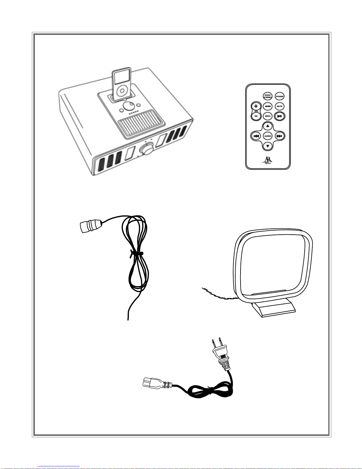
2. Connectthe powerandantenna cablestotheAV100 asoutlined previously.
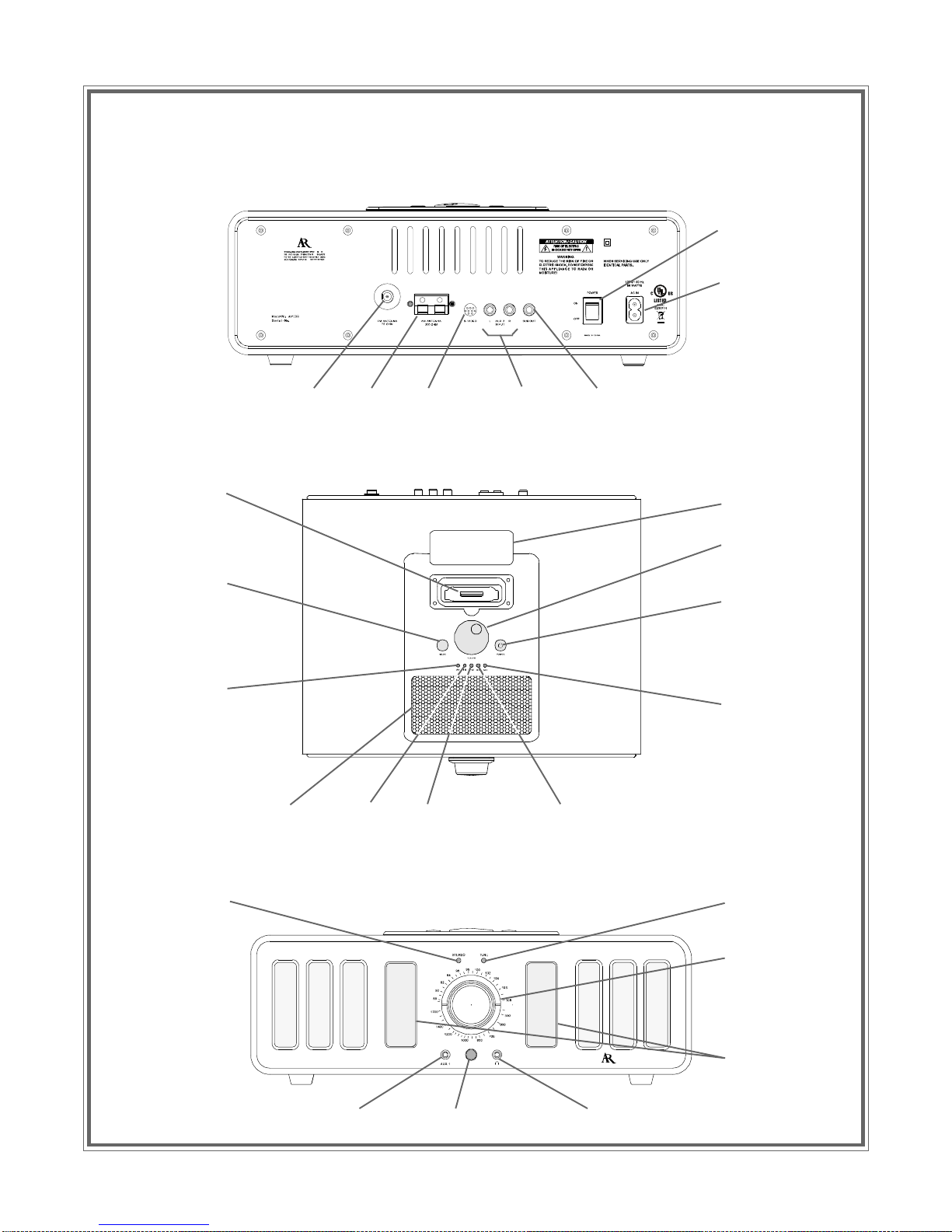
3. Apply line power to theAV100 by pressing the line power rocker switch on the rear of the unit to the on (I)
position; the mode LEDs flash on for 2 seconds and then go out. TheAV100 is now in the standby mode.
4. Press the POWER button on the top of the unit or on the remote control to turn the unit on; the last
operating mode in effect prior to shutdown is indicated by the blue LED on top of the unit, unless the
AV100 is being turned on for the first time.
Note: Despite a low degree of energy consumption in the standby mode, it is recommended that the line
switch be set to the off (O) position if theAV100 is not going to be used for a prolonged period.
5. Select an input source using the MODE button.
Note: If an external subwoofer is to be incorporated into theAV100 system, connect the subwoofer to the
SUB OUT plug at the rear of the unit using an RCA cable with a male RCA jack.
Using the Radio
1. FM Operation: With the supplied FM antenna connected to the FMANTENNAjack at the rear of the unit,
press the MODE switch so the blue FM indicator is lit. Set the FM radio to the desired station using the
uppertuning knobdial,and adjustthe volume tothe desiredlisteninglevel. Ifheadphonesare tobe used,
connect them to the headphones jack ( ) at the front of the unit.
2. AM Operation: With the suppliedAM antenna connected to theAMANTENNAjack at the rear of the unit,
press the MODE switch so the blueAM indicator is lit. Set theAM radio to the desired station using the
bottomtuning knobdial, andadjustthe volumeto thedesired listening level.If headphonesare to beused,
connect them to the headphones jack ( ) at the front of the unit.
Using the AUX Inputs
1. AUX 1 Input: If an external audio source is to be used, such as MP3 player, etc., connect the device to
theAUX 1 input at the front of the unit using a 3.5mm male stereo plug.
2. AUX 2 Input: If an external audio source such as a CD player or other compatible device is to be used,
connect the device to theAUX 2 Land R plugs using an RCAcable with male RCAjacks.
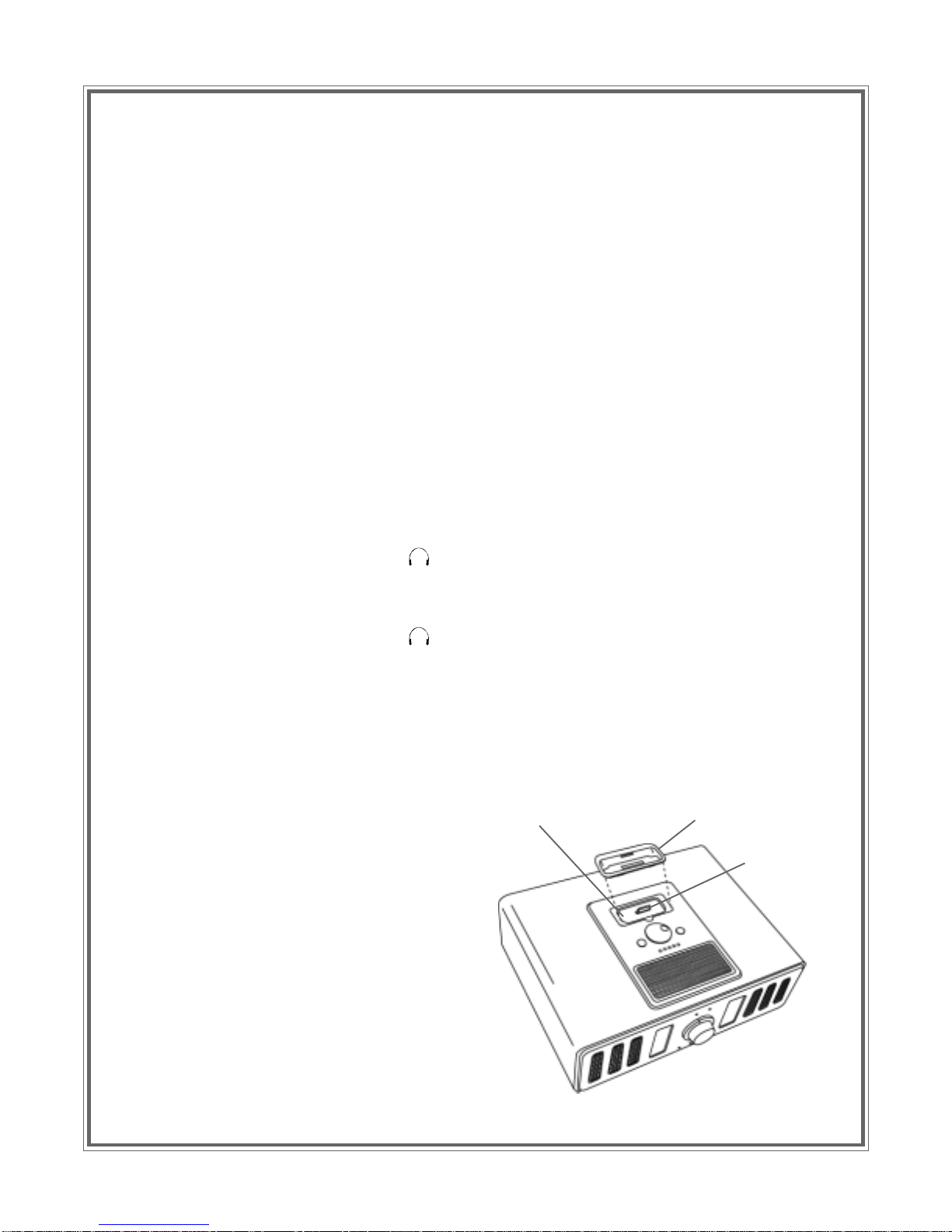
Using the iPod Dock
1. Removetheprotectivecoverfromthe
iPod system connector bay.
2. Choosethecompatibleadapter/holder
for your iPod model and install it in the bay.
Note: TheAV100comesequipped withan
iPod adapter installed in place in the iPod
bay,plus an additionaladapter if needed.
Most iPods come with their own (original)
adapters which can also be used if necessary.
3. Install the iPod carefully onto the iPod
connector and press down lightly until the
iPod bottoms into the recess. The iPod will
be inclined slightly to the rear of theAV100.
ADAPTER/HOLDER
iPodCONNECTORBAY
iPod
CONNECTOR

10 AV100
SpecialAV100 iPod Features
TheAV100 iPodfeature iscompatiblewiththefollowing models:
Thefollowing iPodmodelsare compatibleviatheAUX 1inputand anadditional3.5 stereojack:
------- and other MP3 players
Remote Control Battery Replacement / Disposal
If the remote control stops working properly, the battery may need to be changed as shown below. Use a lithium
button cell (CR2025) and pay attention to the correct polarity.
BatteryReplacement
1. Removethebatteryholder.
2. Insert the battery into the battery holder and insert the battery holder into the remote. Be sure to
observethe correct polarity.
3. Align the battery holder with the remote control and push in until the holderclicks.
BatteryDisposal
Oldbatteries arehazardous waste andmust bedisposed of inaccordance withcurrent regulations.
CR2025
Ö
Charging the iPod:The iPod’s battery is charged when theAV100 is switched on (independent of the input
source selected). This charging function is not supported in the standby mode.
iPod-Classic
5th generation (color display)
20GB 30GB
NOT COMPATIBLE
iPod Video Nano-Classic
3rd generation
1GB 2GB 4GB
NOT COMPATIBLE

AV100 11
Specifications
FrequencyRange:
AM(UL) 530kHz- 1710kHz
FM(UL) 87.5MHz- 108MHz
PowerAmplifier: 2” x 3” magnetic shielded speaker,
10 W RMS @ 10% THD,
FrequencyResponse: 80Hz -20kHz
Input/Output:
Input 120VAC 60Hzpower supply
300 Ohm twin lead to connect theAM antenna
75 Ohm F-connector to connect the FM antenna
RCA-typejackAUX 1 forexternal audio inputsource
3.5mmstereoAUX2 INPUTjack forexternal audio source
input
Output Analogoutput for connectiontoan external subwoofer
S-Video jack for CVBS output
Dimensions (W x H x D) 350mm x 120mm x 290mm
(13.78” x 4.7” x 11.4”)

12 AV100
©2007AudiovoxElectronics Corporation,150 MarcusBlvd., Hauppauge,NY11788
128-8246
This manual suits for next models
1
Table of contents
Other Acoustic Research Docking Station manuals

Acoustic Research
Acoustic Research ARS35I User manual

Acoustic Research
Acoustic Research ARS2I User manual

Acoustic Research
Acoustic Research ARS28I User manual

Acoustic Research
Acoustic Research ARS1i User manual

Acoustic Research
Acoustic Research ARS20i User manual

Acoustic Research
Acoustic Research ARS35I User manual

Acoustic Research
Acoustic Research ARS13 User manual

Acoustic Research
Acoustic Research ARS28I User manual