General Service Instructions
Models 125 and 150 Recorders
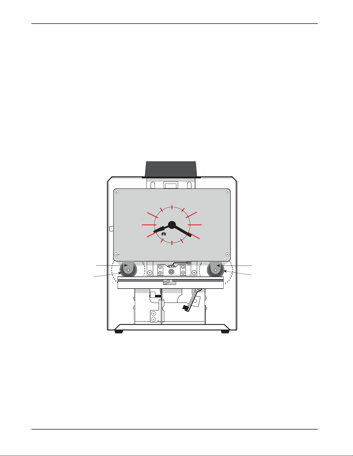
To Remove Case Cover
1) Turn key one quarter turn clockwise.
2) Li t case cover up then orward.
3) Reverse procedure to replace cover.
To Set Time and/or Date
NOTE: Unless your recorder is equipped with
continental (0-23) hours, all PM hours on the time
card will be printed underscored (Ex.: 1:00). To
change the time and/or date ollow these steps:
1) Unplug recorder and remove Case Cover.
2) To Set Day/Date
A) Make sure current time setting is between
midnight and noon (see note above).
B) Push down and release Yellow Lever (see
Figure 1) to set correct day/date.
C) Plug in recorder and punch card to veri y correct
setting. Repeat steps A-C i reading is incorrect
3) To Set Time
A) Push down and release Black Minute Lever
to set the correct time (see Figure 1). I
minute lever does not work, plug in recorder
and wait or minute hand to advance, then
unplug recorder and try lever again. DO NOT
MOVE CLOCK HANDS TO SET THE TIME.
4) To Set Month (i so equipped)
A) Turn Month Knob (see Figure 1) counter-
clockwise to select correct month.
B) Plug in recorder and punch card to veri y correct
setting. Repeat steps A-B i reading is incorrect.
) To Set Year (i so equipped)
A) Insert point o pen into spoke on side o year
wheel and rotate counter-clockwise.
B) Plug in recorder and punch card to veri y correct
setting. Repeat steps A-B i reading is incorrect.
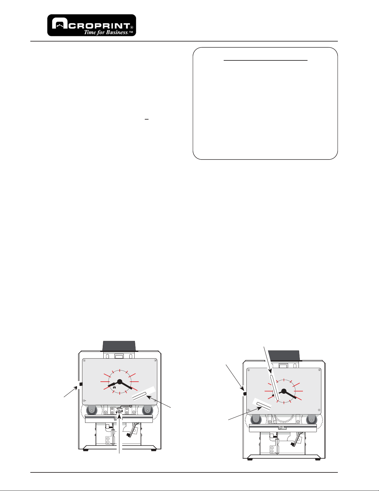
Figure 1
(cover removed)
Month Knob (turn counter-clockwise)
I2 I2
3
4
6
7
8
9
I0 II
CR
O
PR
I
T
N
RALEIGH, N.C. USA
IMPORTANT NOTES
1) The date setting (i so equipped) MUST
be manually reset to the irst o the
month each month, ollowing any month
with less than 31 days.
2) The month and year settings (i so
equipped) MUST be manually reset
every month/year.
3) To reset your recorder a ter a power
ailure ollow the steps 1-5.
4) HINT: I clock is set slightly ahead o actual
time, you may unplug it until it matches the
correct time.
To Set Time and/or Date for Left Print Models
1) Unplug recorder and remove Case Cover.
2) To Set Day/Date
A) Follow the same steps as or standard models,
but note the di erent location o Yellow Day/Date
lever in Figure 2.
3) To Set Time
A) Follow the same steps as or standard models.
4) To Set Month (i so equipped)
A) Move Month Lever (see Figure 2) to extreme
le t position then return slowly to right until an
audible "click" is heard.
B) Plug in recorder and punch card to veri y correct
setting. Repeat steps A-B i reading is incorrect.
) To Set Year (i so equipped)
A) Note that year set lever is located at the rear
o the typehead assembly. Follow the same
steps as or setting the month on le t print
models.
Figure 2
(left print models)
Month Lever
I2 I2
3
4
6
7
8
9
I0 II
CR
O
PR
I
T
N
RALEIGH, N.C. USA
Black Minute
Lever
Yellow
Day/Date
Lever
Black
Minute
Lever Yellow
Day/Date
Lever
Note: Day/Date & Month levers
are shown in cut-away views.
The levers are behind the clock
dial.