Ridetech 41583000 User manual

1997-2004 C5 Corvette Harness Bar
Installation Instructions
812-482-2932
www.ridetech.com
Table of contents
Page 2......... Included components and Hardware List
Page 3......... Getting Started
Page 4......... Bracket Installation
Page 5......... Panel Modification
Page 6......... Finishing Harness Bar
Page 7......... Lap Belt Bracket
Page 8......... Template
Recommended Tools
Installation
Instructions
Part # 41583000 - 1997-2004 C5 Corvette Harness Bar
SOME INTERIOR PANELS WILL NEED TO BE MODIFIED TO INSTALL THIS HARNESS BAR.

1
2
3
4
56
7
8
9
10
11
12
11
13
812-482-2932
www.ridetech.com
2
Installation
Instructions
Installation
Instructions
Major Components .....In the box
Item
#Part # Description QTY
1 41583001 Harness Bar Assembly 1
2 41580001 Harness Bar Bracket -Driver 1
3 41580002 Harness Bar Bracket -Passenger 1
4 90002492 Harness Bar Bracket Clamping Spacer 2
5 41580003 Lap Belt Bracket 1
6 99000007 Lap Belt Eye Bolt 2
7 70012334 Lap Belt Bracket Spacer 2
8 90002493 Lap Belt Bracket Nut 2
Hardware List .....In the box
Item
#QTY Part Number Description Location
9 2 49990008 1/2”-20 x 1 1/2” 12 Point Bolt Harness Bar to Bracket
10 2 49990009 1/2”-20 Locking Flange Nut Harness Bar to Bracket
11 4 99433006 7/16” MIL Spec Washer Eye Bolt to Bracket
12 2 99432002 7/16”-20 Nylok Nut Eye Bolt to Bracket
13 2 99503001 1/2” SAE Flatwasher Lap Belt Bracket Nut

3
Installation
Instructions
812-482-2932
www.ridetech.com
Installation
Instructions
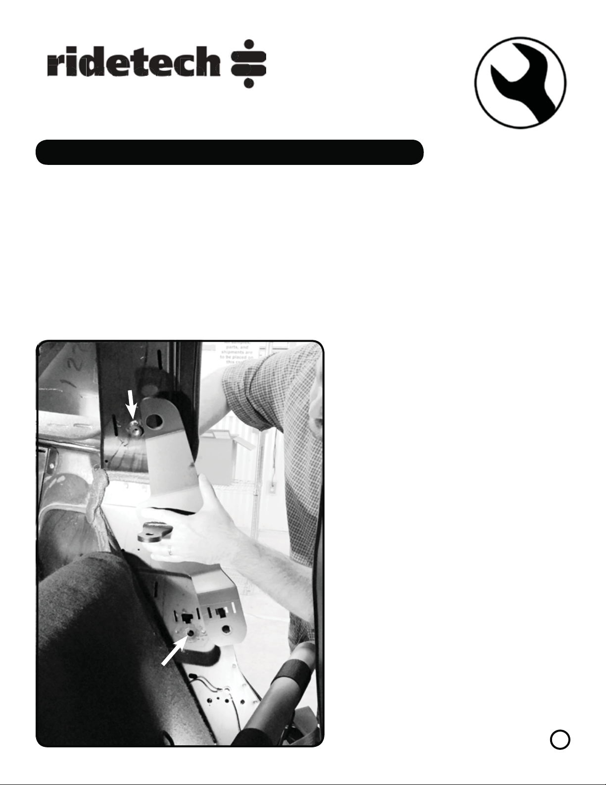
2. Once the Panels are removed from the car,
remove the Shoulder Belt Retractor Assembly.
The kit contains a Driver and Passenger Brack-
et. The straightest edge of the Bracket, is po-
sitioned to the FRONT of the car. The Brack-
et is designed to slip over the Shoulder Belt
Bung and sandwiched behind the Shoulder
Belt Retractor. Driver Side Bracket is shown in
Diagram “2”. Install the Bracket by slipping
the larger Upper Hole over the Shoulder Belt
Bung. Align the Lower Mounting Hole with
the Retractor Mounting Hole.
Getting Started.........
IT IS NECESSARY TO MODIFY SOME INTERIOR PANELS TO INSTALL THE HARNESS BAR BRACKETS,
A TEMPLATE IS PROVIDED IN THESE INSTRUCTIONS.
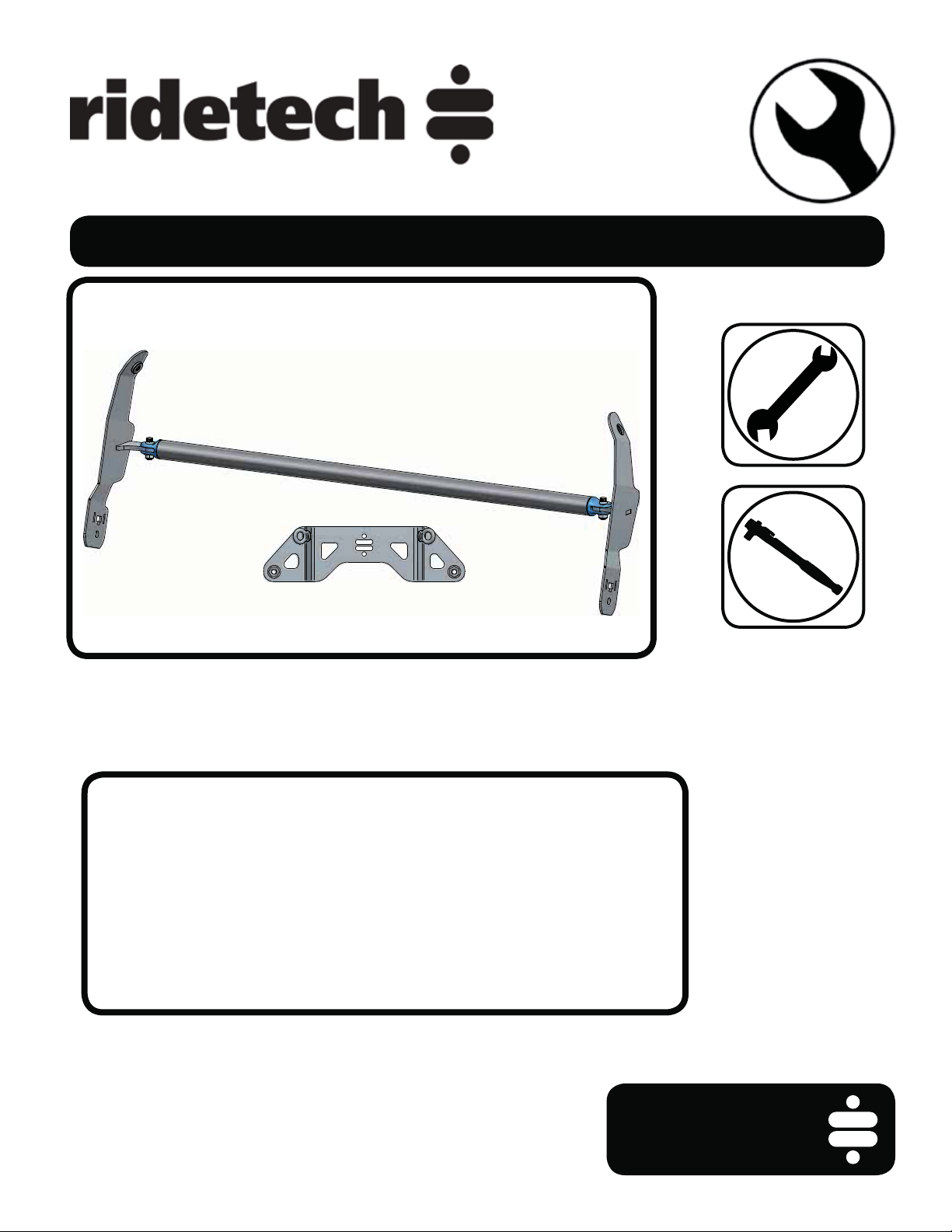
1. The Harness Bar will fit the Coupe and Hardtop, the only difference in the install procedure is the re-
moval and installation of the interior panels. The Panels that will need to be removed are the; Seal Plate/
Kick Panel and both B-Pillar Panels. These panels are all held in by clips that are reusable. Refer to the Fac-
tory Service Manual for Removal & Install Procedure. DO NOT DISCARD ANY HARDWARE OR PARTS.
A second Lap Belt Bracket can be purchased for the Passenger Side from your Ridetech Dealer or
Ridetech, The Kit number is 41583002.
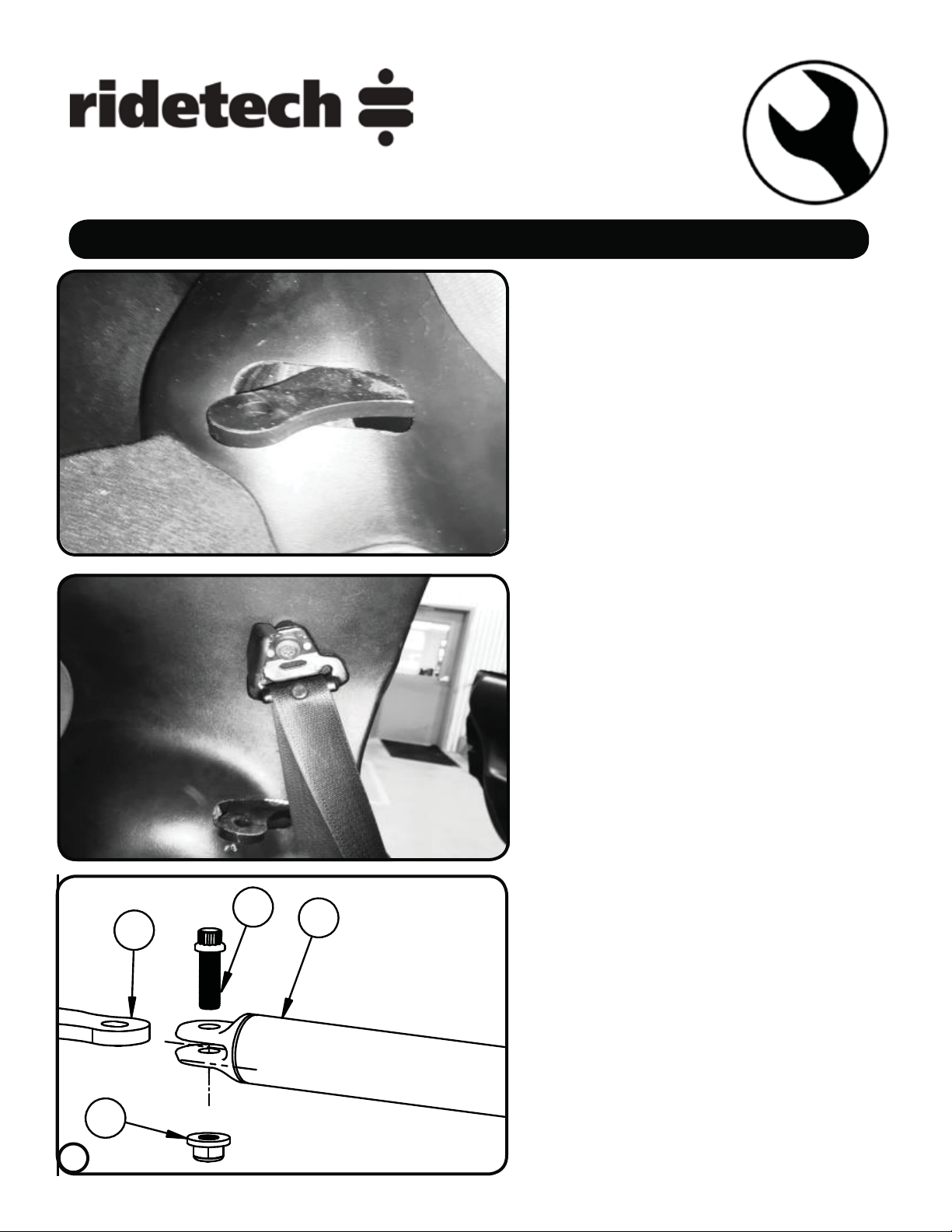
2.
BUNG
RETRACTOR
MOUNTING
LOCATION

812-482-2932
812-482-2932
Installation
Instructions
www.ridetech.com
Installation
Instructions
Bracket Installation
3. Reinstall the Retractor using the OEM Bolt.
DO NOT TIGHTEN until the Upper Clamp is in-
stalled.
NOTE: Make sure the Belt is not twisted and
in the correct Orientation when installing the
Retractor.
4. Install the Upper Clamp on the Shoulder
Belt Bung. The Upper Clamp is Flat on 1 side
and Counter bored on the other. The Counter
bored side goes over the Bung with the Flat
Side out. With the Clamp held in place, in-
sert the Shoulder Belt Bolt. The Shoulder Belt
Mount DOES NOT GET REINSTALLED AT
THIS TIME. Tighten the Retractor Mounting
Bolt and SNUG the Shoulder Belt Bolt, it will
need to be removed and reinstalled later.
5. The Hole for the OEM Shoulder Harness Bolt
will need to be enlarged to 1”. This can be
done with a Uni-Bit or using a Die Grinder.
5.
4
3.
4.
CLAMP

812-482-2932
812-482-2932
Installation
Instructions
www.ridetech.com
Installation
Instructions
Panel Modifications
6. One of the Retaining Clip Posts will need
to cut off of the backside of the Panel. Use
Diagram “6”, “7”, & “8” to aid in location.
7. Diagram “7” shows the Panel with the Post
removed.
8. The Template for Cutting the Panel is lo-
cated on Page 8 of these instructions. First,
verify the size of the template by measuring
the Scale on the Template. Cut the Template
out. Also, cut out the outlined hole in the
Template. Place the Template on the back
side of the Panel, aligning it with the Bottom
Edge and against the Inside Front Edge of the
Panel. Mark the Hole in the Template on the
Panel. This Marked Hole will get Cut Out.
Take your time and make a clean Cut.
8.
5
6.
7.
BOTTOM EDGE
INSIDE FRONT EDGE

1
29
10
812-482-2932
812-482-2932
Installation
Instructions
www.ridetech.com
Installation
Instructions
Finishing Harness Bar
9. Repeat Steps 2 - 8 for Opposite side and Re-
install Panels. The Shoulder Belt Bolt will stay
in place until ALL PANELS are installed. The en-
larged hole will slide over the Bolt. Once the
Panels are installed, the Bar Tab should stick
through the Cut Out Hole looking similar to
Diagram “9”.
10. Remove the Shoulder Belt Bolt. The Panels
will hold the Clamp in place until you Reinstall
the Bolt. Insert the Bolt into the OEM Shoulder
Belt Mount, reattaching the Mount to the Car.
Tighten the Shoulder Harness Mounting Bolt.
Snap the Bolt Cover back on, covering the Bolt
Head.
11. Install the Harness Bar[1] onto the Bracket
Tabs[2] that are sticking through the Panels.
Align the Harness Bar Mounting Holes with
the Tab Holes. Apply Anti-Sieze to the 1/2”-
20 x 1 1/2” Bolts[9] and insert them into the
holes. Next, install the 1/2”-20 Flange Nuts[10]
on the Bolts and Torque them to 75 ftlbs.
11.
6
9.
10.

5
8
13
5
6
11
12
11
812-482-2932
812-482-2932
Installation
Instructions
www.ridetech.com
Installation
Instructions
Lap Belt Bracket Installation
Start by sliding the Drivers Seat forward
and removing the (2) Tracking Mounting
Nuts.
12. Install (1) 7/16” Washer[11] on the Lap
Belt Eye Bolt[6] and insert it into the Lap Belt
Bracket[5]. Install a 2nd 7/16” Washer[11]
on the bottom side of the Bracket and finally
a 7/16”-20 Nylok Nut[12]. Tighten the Nut
with the Eyebolt parallel with the Bracket.
13. Install a Lap Belt Bracket Spacer[7] on
each Seat Track Stud sticking up. Center the
Spacer on the Stud.
14. Sit the Bracket[5] on the Spacer with the
holes centered over the Seat Studs. Center
the Spacers and Bracket on the Studs. Install
a 1/2” Flatwasher on each of the Shoulder
Nut[8]. Thread the Nuts on the Studs with the
Hex up. The Shank side of the Nut will Thread
onto the Studs with the Shank going through
the Bracket and Spacer. Tighten Both Nuts.
If you purchased a 2nd Bracket for the
Passenger side, install in now following
Steps 12-14.
14.
7
12.
13.
FRONT

0”
1”
2”
8
Table of contents
Other Ridetech Automobile Accessories manuals