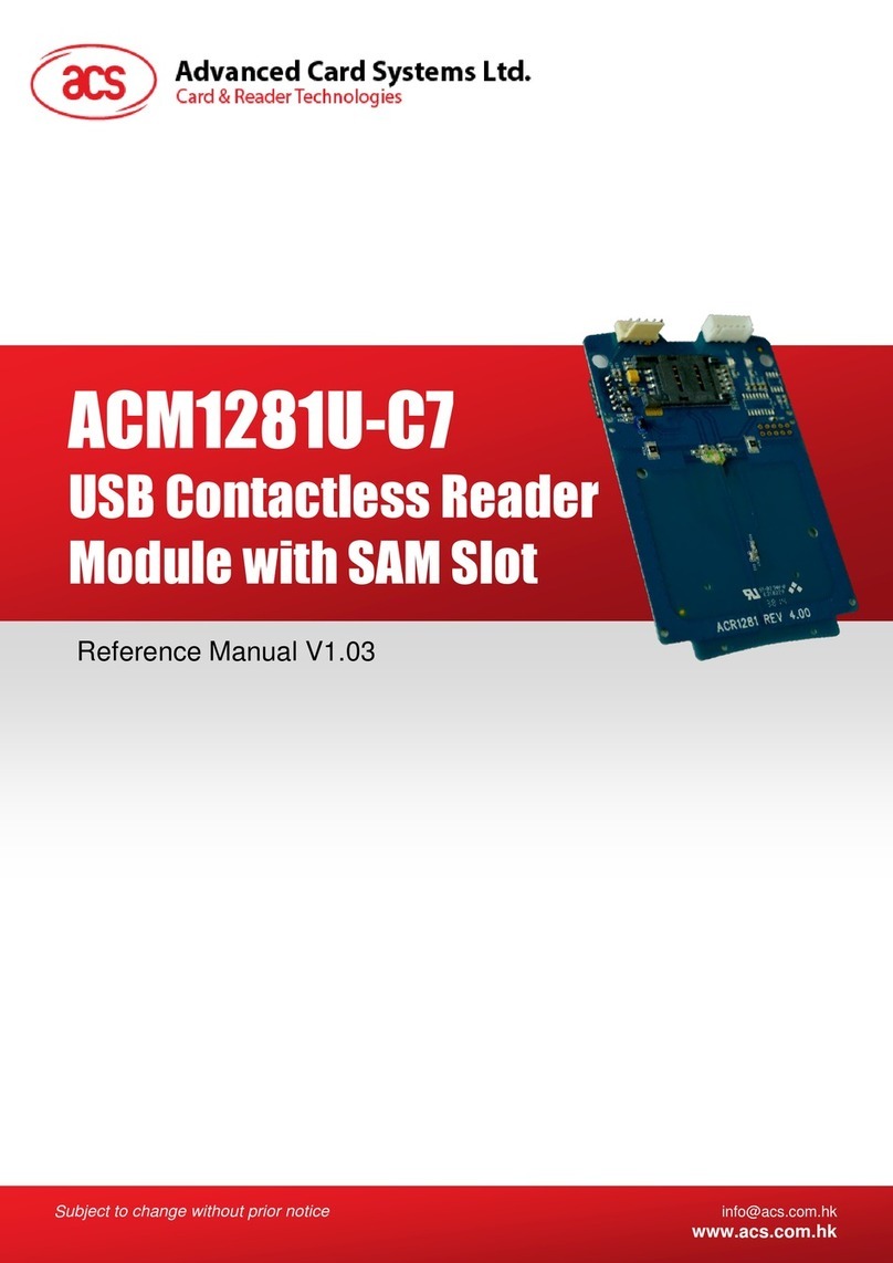
ACS ACM1252U-Y3 User manual

Reference Manual V1.03
ACM1252U-Y3
USB NFC Reader
Module

Page 2 of 92
www.acs.com
.hk
Revision History
Release Date
Revision Description
Version Number
2015-02-13
●Initial Release
1.00
2015-03-26
●Updated Marketing Name
●Updated Section 1.0: Introduction
●Updated Section 2.0: Features
●Updated Section 5.4.2.8: Set Parameter
Data Object
●Updated Section 5.5.2: Authentication for
MIFARE Classic 1K/4K
●Updated Section 5.5.4: Update Binary
Blocks
●Updated Section 5.10: NFC Card Emulation
Mode-related Commands
●Updated Section 5.11.3: Get the PICC
Operating Parameter
1.01
2017-09-20
●Updated Section 1.0: Introduction
●Updated Section 2.0: Features
1.02
2020-03-17
●Updated MIFARE Trademarks
●Re-organized Section 5.0
●Updated Section 5.1 PCSC API
●Updated Section 5.2.4.1 Load
Authentication Keys
●Updated Section 5.2.4.7 Copy Value Block
●Updated Section 5.3.8 Set Automatic PICC
Polling
●Updated Section 5.3.9 Read Automatic
PICC Polling
●Added Section 5.3.12 Set Auto PPS
●Added Section 5.3.13 Read Auto PPS
●Added Section 5.3.14 Read Serial Number
●Updated Section 5.5.4 Set Card Emulation
of MIFARE Ultralight UID
●Updated Section 5.5.5 Set Card Emulation
FeliCa IDm
●Updated Section 5.5.6 Set Card Emulation
Lock Data in NFC
●Added Appendix B. Escape Command
Example
1.03

Page 3 of 92
www.acs.com
.hk
Table of Contents
1.0. Introduction .............................................................................................................5
2.0. Features...................................................................................................................6
3.0. Acronyms and Abbreviations.................................................................................7
4.0. Architecture.............................................................................................................8
5.0. Host Programming (PC-linked) API........................................................................9
5.1. PCSC API.........................................................................................................................9
5.1.1. SCardEstablishContext.............................................................................................9
5.1.2. SCardListReaders..................................................................................................10
5.1.3. SCardConnect........................................................................................................11
5.1.4. SCardControl..........................................................................................................12
5.1.5. SCardTransmit.......................................................................................................14
5.1.6. SCardDisconnect....................................................................................................16
5.1.7. APDU Flow.............................................................................................................17
5.1.8. Escape Command Flow..........................................................................................18
5.2. Contactless Smart Card Protocol ....................................................................................19
5.2.1. ATR Generation .....................................................................................................19
5.2.2. Pseudo APDU for Contactless Interface..................................................................22
5.2.3. APDU Commands for PCSC 2.0 Part 3 (version 2.02 or above)..............................23
5.2.4. PICC Commands for MIFARE® Classic (1K/4K) Memory Cards.............................34
5.2.5. Accessing PCSC-compliant tags (ISO 14443-4)......................................................43
5.2.6. Accessing FeliCa tags............................................................................................45
5.3. Peripherals Control.........................................................................................................46
5.3.1. Get Firmware Version.............................................................................................46
5.3.2. LED Control............................................................................................................47
5.3.3. LED Status.............................................................................................................48
5.3.4. Buzzer Control........................................................................................................49
5.3.5. Buzzer Status.........................................................................................................50
5.3.6. Set LED and Buzzer Status Indicator Behavior for PICC Interface...........................51
5.3.7. Read LED and Buzzer Status Indicator Behavior for PICC Interface .......................52
5.3.8. Set Automatic PICC Polling ....................................................................................53
5.3.9. Read Automatic PICC Polling.................................................................................55
5.3.10. Set PICC Operating Parameter...............................................................................56
5.3.11. Read PICC Operating Parameter............................................................................57
5.3.12. Set Auto PPS.........................................................................................................58
5.3.13. Read Auto PPS......................................................................................................59
5.3.14. Read Serial Number...............................................................................................60
5.4. NFC Peer-to-Peer Mode-related Commands...................................................................61
5.4.1. Initiator Mode-related Commands...........................................................................61
5.4.2. Target Mode-related Commands ............................................................................68
5.5. NFC Card Emulation Mode-related Commands...............................................................78
5.5.1. Enter Card Emulation Mode....................................................................................78
5.5.2. Read Card Emulation Data (MIFARE® Ultralight® or FeliCa)..................................81
5.5.3. Write Card Emulation Data (MIFARE® Ultralight® or FeliCa)..................................82
5.5.4. Set Card Emulation of MIFARE® Ultralight® UID....................................................83
5.5.5. Set Card Emulation FeliCa IDm..............................................................................84
5.5.6. Set Card Emulation Lock Data in NFC....................................................................85
5.6. ACR122U Compatible Commands..................................................................................86
5.6.1. Bi-color LED and Buzzer Control ............................................................................86
5.6.2. Get Firmware Version.............................................................................................88
5.6.3. Get the PICC Operating Parameter.........................................................................89
5.6.4. Set the PICC Operating Parameter.........................................................................90
Appendix A. SNEP Message..........................................................................................91

Page 4 of 92
www.acs.com
.hk
Appendix B. Escape Command Example .....................................................................92
List of Figures
Figure 1 : ACM1252U-Y3 Architecture..............................................................................................8
Figure 2 : ACM1252U-Y3 APDU Flow............................................................................................. 17
Figure 3 : ACM1252U-Y3 Escape Command Flow.......................................................................... 18
Figure 4 : Peer-to-Peer Flow for Initiator Mode................................................................................ 61
Figure 5 : Peer-to-Peer Flow for Target Mode................................................................................. 68
List of Tables
Table 1 : Acronyms and Abbreviations ..............................................................................................7
Table 2 : MIFARE® Classic 1K Memory Map .................................................................................. 36
Table 3 : MIFARE® Classic 4K Memory Map .................................................................................. 36
Table 4 : MIFARE® Ultralight® Memory Map................................................................................... 37
Table 5 : MIFARE® Ultralight® Memory Map (52 bytes).................................................................. 79
Table 6 : FeliCa Memory Map (160 bytes)....................................................................................... 80

Page 5 of 92
www.acs.com
.hk
1.0.Introduction
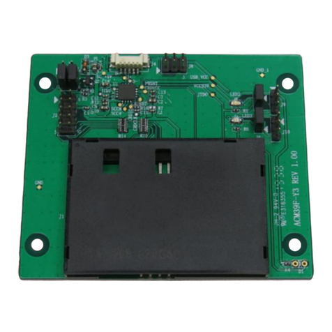
The ACM1252U-Y3 USB NFC Reader Module is a USB PC-linked contactless card reader/writer
developed based on the 13.56 Mhz contactless technology. It supports ISO 14443 Part 4 Type A and
B Cards, MIFARE® cards, FeliCa cards, and all four types of NFC (ISO/IEC 18092 tags).
The ACM1252U-Y3, which is the module version of ACR1252U, supports the three modes of NFC,
namely: NFC card reader/writer, Card emulation and Peer-to-Peer communication modes. The
ACM1252U-Y3 comes with a detachable antenna and an optional USB cable with Molex connector.
This reference manual will discuss in detail how the PC/SC APDU commands were implemented for
the contactless interface and device peripherals of the ACM1252U-Y3.

Page 6 of 92
www.acs.com
.hk
2.0.Features
•USB Full Speed Interface
•Smart Card Reader:
oContactless Interface:
▪Read/Write speed of up to 424 Kbps
▪Built-in antenna for contactless tag access, with card reading distance of up to 50 mm
(depending on tag type)
▪Supports ISO 14443 Part 4 Type A and B Cards, MIFARE Classic®, MIFARE® Mini,
MIFARE Ultralight®, FeliCa, Topaz, and all four types of NFC (ISO/IEC 18092 tags)
▪Built-in anti-collision feature (only one tag is accessed at a time)
▪NFC Support:
▫Card Reader/Writer mode
▫Peer-to-Peer mode
▫Card Emulation mode
oSAM Interface (upon request):
▪One SAM Slot (upon request)
▪Supports ISO 7816-compliant Class A SAM cards
•Built-in Peripherals:
oUser-controllable bi-color LED
oUser-controllable buzzer
•Application Programming Interface:
oSupports PC/SC
oSupports CT-API (through wrapper on top of PC/SC)
•USB Firmware Upgradability
•Supports Android™3.1 and later
1
•Compliant with the following standards:
oEN 60950/IEC 60950
oISO 14443
oISO 18092
oPC/SC
oCCID
oCE
oFCC
oRoHS
oREACH
oVCCI (Japan)
oMicrosoft® WHQL
1
Uses an ACS-defined Android Library

Page 7 of 92
www.acs.com
.hk
3.0.Acronyms and Abbreviations
Acronym/Abbreviation
Description
ATR
Attribute Request and Attribute Response
DEP
Data Exchange Protocol Request and Data Exchange Protocol
Response
DSL
Deselect Request and Deselect Response
PSL
Parameter Selection Request and Parameter Selection Response
RLS
Release Request and Release Response
WUP
Wakeup Request and Wakeup Response
DID
Device ID
BS
Sending bit duration
BR
Receiving bit duration
PP
Protocol Parameters
Gi
Optional information field for Initiator
PFB
Control information for transaction
FSL
Maximum value for the Frame Length
LLCP
Logical Link Control Protocol
Table 1: Acronyms and Abbreviations

Page 8 of 92
www.acs.com
.hk
4.0.Architecture
For communication architecture, the protocol used between the ACM1252U-Y3 and the computer is
CCID protocol. All communications between PICC and SAM are PC/SC compliant.
Figure 1: ACM1252U-Y3 Architecture
ACM1252 PCSC
SAM Interface (Optional)
PCSC Layer
ISO 7816 Parts 1-4
SAM Interface
ISO 14443 Parts 1-
4/ISO 18092
PICC Interface
PICC
(Built-in Antenna)
USB
Interface
(CCID)
Physical
Interface
ACM1252U-Y3
ACM1252 PCSC
PICC Interface
T=CL & T=1
Emulation
SAM Socket
(Optional)

Page 9 of 92
www.acs.com
.hk
#define SCARD_SCOPE_USER 0
SCARDCONTEXT hContext;
int retCode;
void main ()
{
// To establish the resource manager context and assign it to “hContext”
retCode = SCardEstablishContext(SCARD_SCOPE_USER,
NULL,
NULL,
&hContext);
if (retCode != SCARD_S_SUCCESS)
{
// Establishing resource manager context failed
}
else
{
// Establishing resource manager context successful
// Further PCSC operation can be performed
}
}
5.0.Host Programming (PC-linked) API
5.1. PCSC API
This section will describe some of the PCSC API for application programming usage. For more
details, please refer to Microsoft MSDN Library or PCSC workgroup.
5.1.1. SCardEstablishContext
The SCardEstablishContext function establishes the resource manager context within which database
operations are performed.
Refer to: http://msdn.microsoft.com/en-us/library/windows/desktop/aa379479%28v=vs.85%29.aspx
This function should be performed first before any other PCSC operation.
Example:

Page 10 of 92
www.acs.com
.hk
#define SCARD_SCOPE_USER 0
SCARDCONTEXT hContext; // Resource manager context
int retCode;
char readerName [256]; // List reader name
void main ()
{
// To establish the resource manager context and assign to “hContext”
retCode = SCardEstablishContext(SCARD_SCOPE_USER,
NULL,
NULL,
&hContext);
if (retCode != SCARD_S_SUCCESS)
{
// Establishing resource manager context failed
}
else
{
// Establishing resource manager context successful
// List the available reader which can be used in the system
retCode = SCardListReaders (hContext,
NULL,
readerName,
&size);
if (retCode != SCARD_S_SUCCESS)
{
// Listing reader fail
}
if (readerName == NULL)
{
// No reader available
}
else
{
// Reader listed
}
}
}
5.1.2. SCardListReaders
The SCardListReaders function provides the list of readers within a set of named reader groups,
eliminating duplicates.
The caller supplies a list of reader groups and receives the list of readers within the named groups.
Unrecognized group names are ignored. This function only returns readers within the named groups
that are currently attached to the system and available for use.
Refer to: http://msdn.microsoft.com/en-us/library/windows/desktop/aa379793%28v=vs.85%29.aspx
Example:

Page 11 of 92
www.acs.com
.hk
#define SCARD_SCOPE_USER 0
SCARDCONTEXT hContext; // Resource manager context
SCARDHANDLE hCard; // Card context handle
unsigned long dwActProtocol; // Establish active protocol
int retCode;
char readerName [256]; // List reader name
char rName [256]; // Reader name for connection
void main ()
{
…
if (readerName == NULL)
{
// No reader available
}
else
{
// Reader listed
rName = "ACS ACR1252 CL Reader PICC 0"; // Depends on what
reader be used
// Should connect to
PICC interface
retCode = SCardConnect(hContext,
rName,
SCARD_SHARE_SHARED,
SCARD_PROTOCOL_T0,
&hCard,
&dwActProtocol);
if (retCode != SCARD_S_SUCCESS)
{
// Connection failed (May be because of incorrect reader
name, or no card was detected)
}
else
{
// Connection successful
}
}
}
}
5.1.3. SCardConnect
The SCardConnect function establishes a connection (using a specific resource manager context)
between the calling application and a smart card contained by a specific reader. If no card exists in
the specified reader, an error is returned.
Refer to: http://msdn.microsoft.com/en-us/library/windows/desktop/aa379473%28v=vs.85%29.aspx
Example:

Page 12 of 92
www.acs.com
.hk
#define SCARD_SCOPE_USER 0
#define EscapeCommand 0x310000 + 3500*4
SCARDCONTEXT hContext; // Resource manager context
SCARDHANDLE hCard; // Card context handle
unsigned long dwActProtocol; // Established active protocol
int retCode;
char readerName [256]; // Lists reader name
char rName [256]; // Reader name for connection
BYTE SendBuff[262], // APDU command buffer
RecvBuff[262]; // APDU response buffer
BYTE FWVersion [20], // For storing firmware
version message
BYTE ResponseData[50]; // For storing card response
DWORD SendLen, // APDU command length
RecvLen; // APDU response length
void main ()
{
…
rName = "ACS ACR1252 CL Reader PICC 0"; // Depends on what
reader will be used
// Should connect to
PICC interface
retCode = SCardConnect(hContext,
rName,
SCARD_SHARE_DIRECT,
SCARD_PROTOCOL_T0| SCARD_PROTOCOL_T1,
&hCard,
&dwActProtocol);
if (retCode != SCARD_S_SUCCESS)
{
// Connection failed (may be because of incorrect reader
name, or no card was detected)
}
else
{
// Connection successful
RecvLen = 262;
// Get firmware version
SendBuff[0] = 0xE0;
SendBuff[1] = 0x00;
SendBuff[2] = 0x00;
SendBuff[3] = 0x18;
SendBuff[4] = 0x00;
5.1.4. SCardControl
The SCardControl function gives you direct control of the reader. You can call it any time after a
successful call to SCardConnect and before a successful call to SCardDisconnect. The effect on the
state of the reader depends on the control code.
Refer to: http://msdn.microsoft.com/en-us/library/windows/desktop/aa379474%28v=vs.85%29.aspx
Note: Commands from Peripherals Control use this API for sending.
Example:

Page 13 of 92
www.acs.com
.hk
SendLen = 5;
retCode = SCardControl ( hCard,
EscapeCommand,
SendBuff,
SendLen,
RecvBuff,
RecvLen,
&RecvLen);
if (retCode != SCARD_S_SUCCESS)
{
// APDU sending failed
return;
}
else
{
// APDU sending successful
// The RecvBuff stores the firmware version message.
for (int i=0;i< RecvLen-5;i++)
{
FWVersion[i] = RecvBuff [5+i];
}
}
// Connection successful
RecvLen = 262;
// Turn Green LED on, turn Red LED off
SendBuff[0] = 0xE0;
SendBuff[1] = 0x00;
SendBuff[2] = 0x00;
SendBuff[3] = 0x29;
SendBuff[4] = 0x01;
SendBuff[5] = 0x02; // Green LED On, Red LED off
SendLen = 6;
retCode = SCardControl ( hCard,
EscapeCommand,
SendBuff,
SendLen,
RecvBuff,
RecvLen,
&RecvLen);
if (retCode != SCARD_S_SUCCESS)
{
// APDU sending failed
return;
}
else
{
// APDU sending success
}

Page 14 of 92
www.acs.com
.hk
#define SCARD_SCOPE_USER 0
SCARDCONTEXT hContext; // Resource manager context
SCARDHANDLE hCard; // Card context handle
unsigned long dwActProtocol; // Established active protocol
int retCode;
char readerName [256]; // List reader name
char rName [256]; // Reader name for connect
BYTE SendBuff[262], // APDU command buffer
RecvBuff[262]; // APDU response buffer
BYTE CardID [8], // For storing the FeliCa IDM/
MIFARE® UID
BYTE ResponseData[50]; // For storing card response
DWORD SendLen, // APDU command length
RecvLen; // APDU response length
SCARD_IO_REQUEST ioRequest;
void main ()
{
…
rName = "ACS ACR1252 CL Reader PICC 0"; // Depends on what reader
should be used
// Should connect to PICC
interface
retCode = SCardConnect(hContext,
rName,
SCARD_SHARE_SHARED,
SCARD_PROTOCOL_T0,
&hCard,
&dwActProtocol);
if (retCode != SCARD_S_SUCCESS)
{
// Connection failed (May be because of incorrect reader
name, or no card was detected)
}
else
{
// Connection successful
ioRequest.dwProtocol = dwActProtocol;
ioRequest.cbPciLength = sizeof(SCARD_IO_REQUEST);
RecvLen = 262;
5.1.5. SCardTransmit
The SCardTransmit function sends a service request to the smart card and expects to receive data
back from the card.
Refer to: http://msdn.microsoft.com/en-us/library/windows/desktop/aa379804%28v=vs.85%29.aspx
Note: APDU Commands (i.e. the commands sent to connected card, PICC Commands for
MIFARE® Classic (1K/4K) Memory Cards and Pseudo APDU for Contactless Interface) use this
API for sending.
Example:

Page 15 of 92
www.acs.com
.hk
// Get MIFARE UID/ FeliCa IDM
SendBuff[0] = 0xFF;
SendBuff[1] = 0xCA;
SendBuff[2] = 0x00;
SendBuff[3] = 0x00;
SendBuff[4] = 0x00;
SendLen = 5;
retCode = SCardTransmit( hCard,
&ioRequest,
SendBuff,
SendLen,
NULL,
RecvBuff,
&RecvLen);
if (retCode != SCARD_S_SUCCESS)
{
// APDU sending failed
return;
}
else
{
// APDU sending successful
// The RecvBuff stores the IDM for FeliCa / the UID for
MIFARE.
// Copy the content for further FeliCa access
for (int i=0;i< RecvLen-2;i++)
{
CardID [i] = RecvBuff[i];
}
}

Page 16 of 92
www.acs.com
.hk
#define SCARD_SCOPE_USER 0
SCARDCONTEXT hContext; // Resource manager context
SCARDHANDLE hCard; // Card context handle
unsigned long dwActProtocol; // Established active protocol
int retCode;
void main ()
{
…
// Connection successful
…
retCode = SCardDisconnect(hCard,SCARD_RESET_CARD);
if (retCode != SCARD_S_SUCCESS)
{
// Disconnection failed
}
else
{
// Disconnection successful
}
}
}
5.1.6. SCardDisconnect
The SCardDisconnect function terminates a connection previously opened between the calling
application and a smart card in the target reader.
Refer to: http://msdn.microsoft.com/en-us/library/windows/desktop/aa379475%28v=vs.85%29.aspx
This function ends the PCSC Operation.
Example:

Page 17 of 92
www.acs.com
.hk
5.1.7. APDU Flow
Figure 2: ACM1252U-Y3 APDU Flow
SCardEstablishContext
SCardListReaders
Reader
present?
SCardConnect
Connection
successful?
SCardTransmit
SCardDisconnect
Start
End
Yes
No
Yes
No

Page 18 of 92
www.acs.com
.hk
5.1.8. Escape Command Flow
Figure 3: ACM1252U-Y3 Escape Command Flow
SCardEstablishContext
SCardListReaders
Reader
present?
SCardConnect
SCardControl
SCardDisconnect
Start
End
Yes
No

Page 19 of 92
www.acs.com
.hk
5.2. Contactless Smart Card Protocol
5.2.1. ATR Generation
If the reader detects a PICC, an ATR will be sent to the PCSC driver to identify the PICC.
5.2.1.1. ATR Format for ISO 14443 Part 3 PICCs
Byte
Value
Designation
Description
0
3Bh
Initial Header
1
8Nh
T0
Higher nibble 8 means: no TA1, TB1, TC1 only
TD1 is following.
Lower nibble N is the number of historical bytes
(HistByte 0 to HistByte N-1)
2
80h
TD1
Higher nibble 8 means: no TA2, TB2, TC2 only
TD2 is following.
Lower nibble 0 means T = 0
3
01h
TD2
Higher nibble 0 means no TA3, TB3, TC3, TD3
following.
Lower nibble 1 means T = 1
4
To
3+N
80h
T1
Category indicator byte, 80 means A status
indicator may be present in an optional
COMPACT-TLV data object
4Fh
Tk
Application identifier Presence Indicator
0Ch
Length
RID
Registered Application Provider Identifier (RID) #
A0 00 00 03 06
SS
Byte for standard
C0 .. C1h
Bytes for card name
00 00 00 00h
RFU
RFU # 00 00 00 00
4+N
UU
TCK
Exclusive-oring of all the bytes T0 to Tk
Example:
ATR for MIFARE Classic 1K = {3B 8F 80 01 80 4F 0C A0 00 00 03 06 03 00 01 00 00 00 00 6Ah}
Where:
Length (YY) = 0Ch
RID = {A0 00 00 03 06h} (PC/SC Workgroup)
Standard (SS) = 03h (ISO 14443A, Part 3)
Card Name (C0 .. C1) = {00 01h} (MIFARE Classic 1K)
Standard (SS) = 03h: ISO 14443A, Part 3
= 11h: FeliCa

Page 20 of 92
www.acs.com
.hk
Card Name (C0 .. C1)
00 01: MIFARE Classic 1K
00 38: MIFARE Plus SL2 2K
00 02: MIFARE Classic 4K
00 39: MIFARE Plus SL2 4K
00 03: MIFARE Ultralight
00 30: Topaz and Jewel
00 26: MIFARE Mini
00 3B: FeliCa
00 3A: MIFARE Ultralight C
FF 28: JCOP 30
00 36: MIFARE Plus SL1 2K
FF [SAK]: undefined tags
00 37: MIFARE Plus SL1 4K
5.2.1.2. ATR Format for ISO 14443 Part 4 PICCs
Byte
Value
Designation
Description
0
3Bh
Initial Header
1
8Nh
T0
Higher nibble 8 means: no TA1, TB1, TC1 only
TD1 is following.
Lower nibble N is the number of historical bytes
(HistByte 0 to HistByte N-1)
2
80h
TD1
Higher nibble 8 means: no TA2, TB2, TC2 only
TD2 is following.
Lower nibble 0 means T = 0
3
01h
TD2
Higher nibble 0 means no TA3, TB3, TC3, TD3
following.
Lower nibble 1 means T = 1
4
to
3 + N
XX
T1
Historical Bytes:
ISO 14443-A:
The historical bytes from ATS response. Refer to
the ISO14443-4 specification.
ISO 14443-B:
Byte 1-4
Byte 5-7
Byte 8
Application
Data from
ATQB
Protocol Info
Byte from
ATQB
Higher
nibble=MBLI
from ATTRIB
command
Lower nibble
(RFU)=0
XX
XX
XX
Tk
4+N
UU
TCK
Exclusive-oring of all the bytes T0 to Tk
Table of contents
Other ACS Control Unit manuals
Popular Control Unit manuals by other brands

Dakota Digital
Dakota Digital BIM-17-2 manual

Spirax Sarco
Spirax Sarco M10HPi ISO Series Installation and maintenance instructions

ABB
ABB FCB400 Series Configuration guide

Airborne Innovations
Airborne Innovations Picoradio manual

Tyco
Tyco ACC-1 user manual

Texas Instruments
Texas Instruments AWR2544LOP user guide

Trane
Trane Symbio 700 FIAOPTN001 Series installation guide

Festo
Festo CPX-FB6 manual

SDC
SDC 1786 RIM DEVICE installation instructions

HYDAC FILTER SYSTEMS
HYDAC FILTER SYSTEMS FluidControl FCU 8111 Operating and maintenance instructions

Coelbo
Coelbo 1305TT Installation and operating instructions

Beninca
Beninca DA.AXE operating instructions