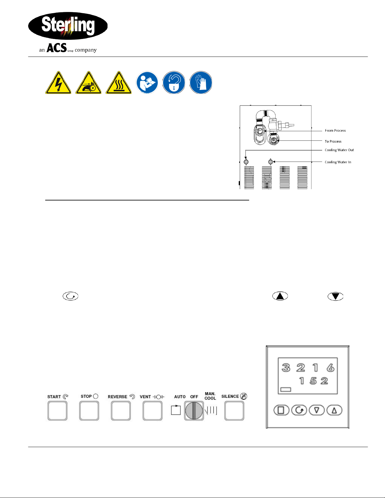
Royal Series 2016-U Series Oil Temperature Control Units
Reference Manual (PN: 882.12044.00) for
Complete Operation and Installation Instructions
(Available online at www.sterlco.com)
Sterling Products, Inc. Part No: 682.98487.08
2900 S. 160th Street • New Berlin, WI 53151 USA Bulletin No: HC2-340
Tel. 262.641.8600 •Fax 262.641.8653
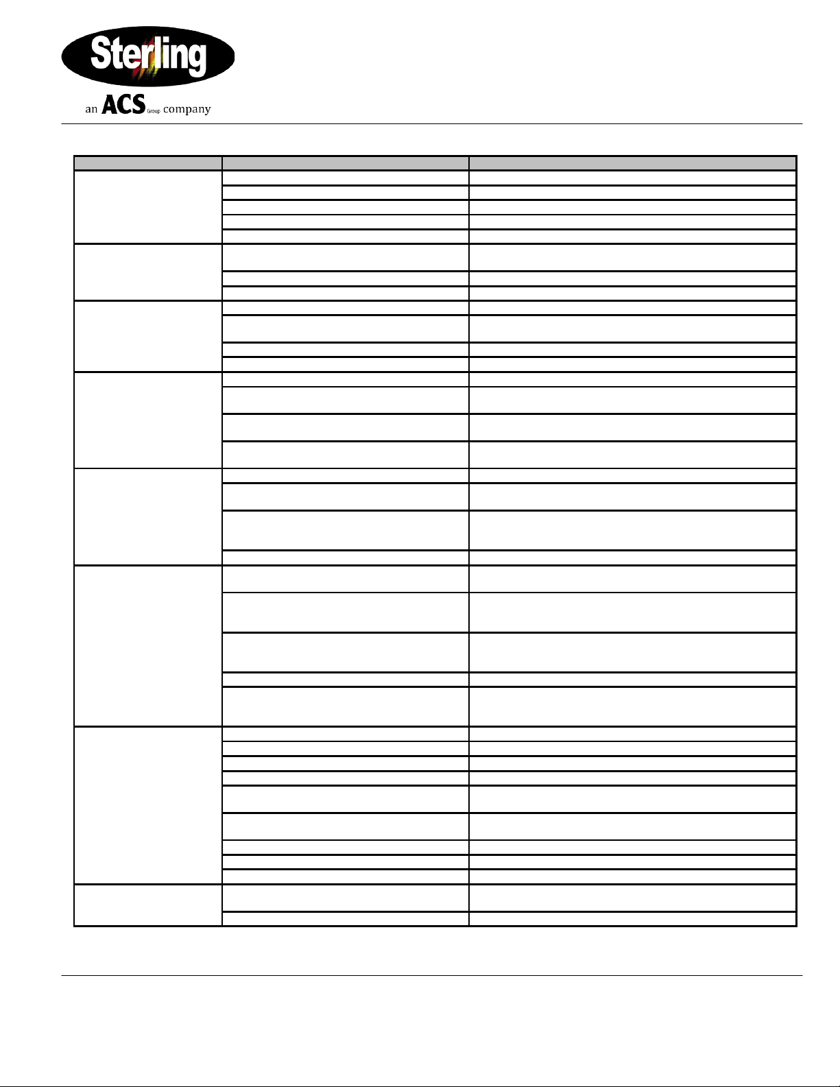
Troubleshooting - Quick Guide
Check main disconnect, fuses, wiring, and power lead to unit.
Wrong voltage supplied to unit
Voltage must be within plus or minus 10% of nameplate rating
Defective START push button
Control circuit fuse blown
Defective control transformer
Check transformer. Replace if necessary.
Broken or loose wire in pump motor control
circuit
Pump motor contactor holding coil is open
Reset and test each leg for balanced amp draws
Temperature
fluctuations/rapid cycling
from hot to cold.
Undersized connectors/lines.
Increase size of connectors/fluid lines.
Long connecting lines between unit and mold.
Move the unit closer to the process and shorten connecting
lines.
Check process for debris or deposits. Clean mold.
Carbon build-up in unit piping or fittings.
Clean or replace affected piping. Replace fluid.
Unit overheats or does not
cool.
Water supply to unit is turned OFF.
Water drain is plugged or excessive back
pressure in drain line.
Clear drain line or eliminate back pressure condition.
Heat exchanger tubes plugged by lime
deposits.
Remove tube bundles; clean/replace as required.
Test solenoid valve by switching to Manual Cool mode and
listen for valve operation. Replace if faulty.
Unit does not heat
properly/cannot achieve
set point.
Loss of fluid in process.
Check all lines/connections/fittings.
Allow vent timer to run out; or, check valve operation when unit
is cold by opening the fill port.
Faulty/dirty solenoid valve; usually detected
when there is a steady stream or trickle of
water out of the drain line.
Switch to Manual Cool mode several times to flush valve. If the
leak continues, disconnect the power to the unit, turn off the
water supply, and clean or replace the solenoid.
Defective heater contactor.
Visual inspection of coil and contacts. Repair/replace defective
contactors.
Defective immersion heater.
Check resistance on all three (3) legs of heater with an
ohmmeter. If not all equal, contact factory for replacement
heater.
Check heater tank for scorched/discolored paint. Check
resistance on all three (3) legs of heater with an ohmmeter.
Replace heater as needed.
Controller heater output open.
Check the heater output with an ohmmeter to ground. It should
read in the mega-ohm range. Infinite or zero readings indicate a
defective output.
Rapid drop in pressure/no
pressure.
Leaks in connecting lines.
Inspect/replace faulty line or connection.
Air in circulating lines.
Preform venting sequence in Chapter 3.
Check fluid level in sight glass. Add fluid if required.
Drain water from low point in piping (see Chapter 3), or boil
water off.
Allow vent timer to run out; or, check valve operation when unit
is cold by opening the fill port.
Check motor; rewire if necessary. (See electrical diagrams)
Pump repair/adjustment needed.
Adjust head spacing or replace warn pump components.
Drain water from low point in piping ( see Chapter 3), or boil
water off.
Drain and flush system. Replace fluid.