ACTiSYS IR8200D Guide

48511 Warm Springs Blvd., Suite 206, Fremont, CA 94539
Tel: (510) 490-8024 Fax: (510) 623-7268
Website: http://www.actisys.com E-mail: irda-info@actisys.com
ACT-IR8200D
IrDA Compliant Protocol Processor
Design Specification
© Copyright 2004 ACTiSYS Corporation
All Rights Reserved
Nov. 10, 2004 Rev.0.2

The Infrared Wireless Expert ACT-IR8200D
Design Specification
Revision History
Revision Date Comment
Rev. 0.1 11/03/2004 Created
Rev. 0.2 11/10/2004 Add comset_IR100SD and others on chapter 6,7
© Copyright 2004 ACTiSYS Corp. Page 1 of 20 Nov. 10, 2004
Rev. 0.2

The Infrared Wireless Expert ACT-IR8200D
Design Specification
Table of Contents
1. Features........................................................................................3
2. Overview.......................................................................................5
3. Pins Description............................................................................6
4. Device Operation ..........................................................................8
5. Firmware architecture .................................................................10
6. How to configure IR8200D?........................................................12
7. How to make IR8200D work? .....................................................15
8. CHARACTERISTICS AND SPECIFICATION .............................16
9. Application Circuit .......................................................................18
10. Package Dimensions ................................................................19
© Copyright 2004 ACTiSYS Corp. Page 2 of 20 Nov. 10, 2004
Rev. 0.2

The Infrared Wireless Expert ACT-IR8200D
Design Specification
1. Features
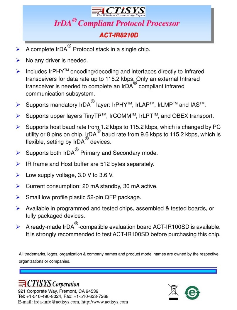
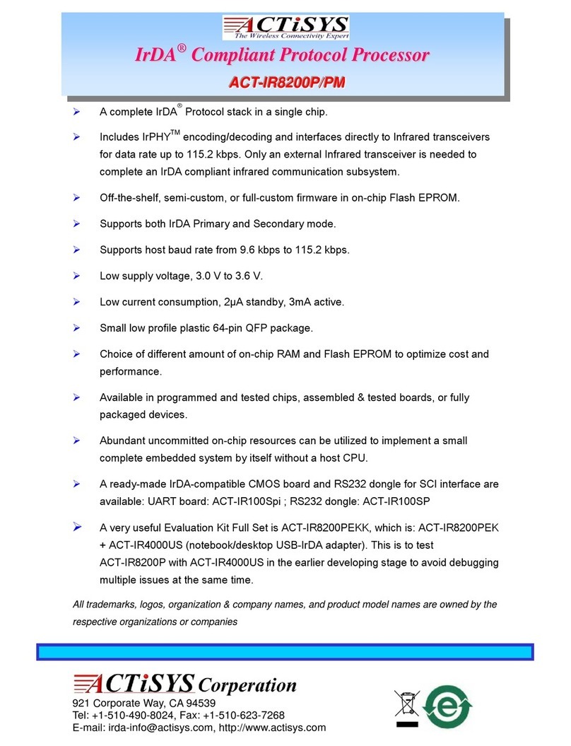
A complete IrDA Protocol stack in a single chip.
No any driver program is needed.
Includes IrPHY encoding/decoding and interfaces directly to Infrared transceivers for data rate
up to 115.2kbit/s. Only an external Infrared transceiver is needed to complete an IrDA compliant
infrared communication subsystem.
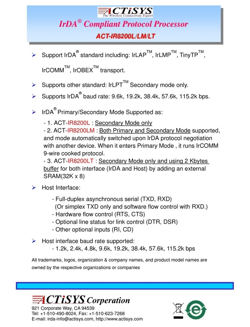
Supports mandatory IrDA layer: IrPHY, IrLAP, IrLMP and IAS.
Supports upper layers TinyTP, IrCOMM, IrLPT, and OBEX transport.
Supports host baud rate from 1.2kbit/s to 115.2kbit/s, which is changed by PC utility or 8 pins on
chip. IrDA baud rate from 9.6kbit/s to 115.2kbit/s, which is flexible, setting by IrDA devices.
IR frame and Host buffer are 2048 bytes separately.
Low supply voltage, 3.0 V to 3.6 V.
Current consumption: 20mA standby, 30mA active.
Small low profile plastic 52-pin QFP package.
Available in programmed and tested chips, assembled & tested boards, or fully packaged
devices.
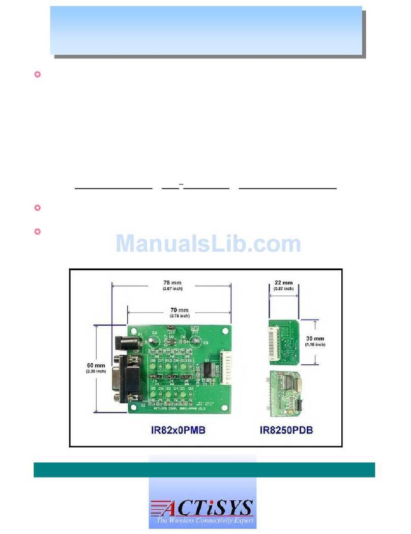
A ready IrDA-compatible evaluation board ACT-IR100SD is available. IR100SD is strongly
recommended to test before purchase IR8200D chip.
A very useful Evaluation Kit Full Set is ACT-IR100SDK, which is: IR100SD + IR4000US
(notebook/desktop USB-IrDA adapter). This is to test IR100D (connected to your device),
to exchange IrDA data with IR4000US (connected to PC USB port), running hyper-terminal
on top of Windows IrDA driver. To avoid debugging multiple issues: e.g. PDA application
IrDA SW activated and behaves properly, with the matching protocol layer? IR100SD to host
interface issues (UART data rates, flow control, data bit/parity/stop bit, UART signal pins,
power levels)? Or performance issues (throughput, distance, error rate/dropping bits)?
© Copyright 2004 ACTiSYS Corp. Page 3 of 20 Nov. 10, 2004
Rev. 0.2

The Infrared Wireless Expert ACT-IR8200D
Design Specification
ACT-IR8200D
© Copyright 2004 ACTiSYS Corp. Page 4 of 20 Nov. 10, 2004
Rev. 0.2

The Infrared Wireless Expert ACT-IR8200D
Design Specification
2. Overview
The ACT-IR8200D is a low cost, high performance and high-integration micro-controller, with on-chip
IrDA protocol stack and on-chip Infrared physical encoder/decoder. It provides a serial interface
(UART) to a host device that intends to have Infrared communication capability. The host device can
be any equipment or devices that need to communicate with IrDA enabled portable or tablet PC,
PDA, cellular phone and hand held data terminal, via IrDA beam and protocol but has only a wired
serial interface. The ACT-IR8200D will handle all the detail regard IrDA protocols. It sends and
receives only user data to/from the host device via the wired serial interface with hardware
flow-control. IrDA has two modes; one is Primary, and the other is Secondary. The difference
between these two modes is that a Primary mode device initiates the discovery, negotiation and
connection sequence to Secondary mode device, and decides IrDA protocol parameters. Secondary
mode device always waits for commands from Primary mode device. Both modes can run different
protocols, and both may send or receive user data. ACT-IR8200D supports both Primary and
Secondary modes. Fig.1 is system diagram.
Fig. 1
© Copyright 2004 ACTiSYS Corp. Page 5 of 20 Nov. 10, 2004
Rev. 0.2

The Infrared Wireless Expert ACT-IR8200D
Design Specification
3. Pins Description
Symbol Pin No. I/O
Type Descriptions
VDD 6,8,33,47 Digital and Analog supply voltage, positive terminal.
GND 9,19,45 Ground.
PD1 1 I/O General I/O pin, not used.
PC7 2 I/O General I/O pin, not used.
TDO 3 O JTAG signals, not used.
TDI 4 I JTAG signals, not used.
DEBUG 5 O JTAG signals, not used.
TERR 7 O JTAG signals, not used.
TSTAT 10 O JTAG signals, not used.
VSTBY 11 I SRAM standby voltage input, not used.
TCK 12 I JTAG signals, not used.
TMS 13 O JTAG signals, not used.
P4.7 14 I/O General I/O pin, not used.
P4.6 15 I/O General I/O pin, not used.
P4.5 16 I/O General I/O pin, not used.
P4.4 17 I/O General I/O pin, not used.
P4.3 18 I/O General I/O pin, not used.
P4.2/LED 20 O Status LED output.
P4.1 21 I/O General I/O pin, not used.
P4.0 22 I/O General I/O pin, not used.
P3.0/RXD 23 I Receive data signal from host, same as UART receiver.
P3.1/TXD 24 O Transmit data signal to host, same as UART transmitter.
P3.2 25 I/O General I/O pin, not used.
P3.3 26 I/O General I/O pin, not used.
P3.4 27 I/O General I/O pin, not used.
P3.5/RTS 28 O Ready to send. If low then host can send data to 8200D.
P3.6 29 I/O General I/O pin, not used.
P3.7 30 I/O General I/O pin, not used.
XTAL1 31 I Oscillator input pin for system clock. 22.1184MHz is required.
XTAL2 32 O Oscillator output pin for system clock.
P1.0 34 I/O General I/O pin, not used.
P1.1/DTR 35 O Device terminal is ready. If low means IR8200D established IrDA link.
P1.2/IrDA_RXD 36 I Infrared signal input pin from IrDA transceiver.
P1.3/IrDA_TXD 37 I Infrared signal output pin to IrDA transceiver.
P1.4/DCD 38 I Device carrier detect, not used.
© Copyright 2004 ACTiSYS Corp. Page 6 of 20 Nov. 10, 2004
Rev. 0.2

The Infrared Wireless Expert ACT-IR8200D
Design Specification
PIN Description (Continued)
Symbol Pin
No.
I/O
Type Descriptions
P1.5/DSR 39 I Data Set Ready. If low means host is ready and IR8200D can
start to establish IrDA link(If Primary mode) or ready to be link
by other IrDA Primary device(if secondary mode) .
P1.6/CTS 40 I Clear to send. If low then 8200D is allowed sending data to host.
P1.7/RI 41 I Ring-in, not used.
PB7 42 I Configuration selector. Hi means use default setting. Low means
use the setting on PB4~PB0.
Default setting means the configuration is setting by
Comset_IR100SD program.
PB6 43 I Not used.
RESET_IN 44 I Reset IR8200D signal. Pull it low to reset.
PB5 46 I Not used.
PB4 48 I DSR selector. Hi means use the default setting. Low means
ignore DSR and IR8200D will be ready no matter DSR signal
(p
in 39
)
is hi or low.
PB3 49 I CTS selector. Hi means use the default setting. Low means
ignore CTS and IR8200D will send data to host no matter CTS
signal (pin 40) is hi or low.
PB2 50 I Host interface baud rate selector pin 2. See PB0.
PB1 51 I Host interface baud rate selector pin 1. See PB0
PB0 52 I Host interface baud rate selector pin 0.
PB2 PB1 PB0 host baud rate
lo lo lo 1.2kbit/s
lo lo hi 2.4kbit/s
lo hi lo 4.8kbit/s
lo hi hi 9.6kbit/s
hi lo lo 19.2kbit/s
hi lo hi 38.4kbit/s
hi hi lo 57.6kbit/s
hi hi hi 115.2kbit/s
© Copyright 2004 ACTiSYS Corp. Page 7 of 20 Nov. 10, 2004
Rev. 0.2

The Infrared Wireless Expert ACT-IR8200D
Design Specification
4. Device Operation
4.1 RESET circuit
IR8200D will be reset when RESET_IN is pulled
low. It needs a 10K ohms resistor, 0.1uF
capacitor and a diode to implement the reset
circuit. Please refer to right figure.
4.2 Crystal circuit
IR8200D needs a specific
clock to operate, please refer
to right figure.
4.3 Host Interface
The host interface of IR8200D is a full-duplex asynchronous serial data interface. The data bytes are
transmitted via TX and received via RX. Each data byte consists of one start bit (0), 8 data bits (LSB
first, MSB last) and a stop bit (1).
4.4 IR port interface
© Copyright 2004 ACTiSYS Corp. Page 8 of 20 Nov. 10, 2004
Rev. 0.2

The Infrared Wireless Expert ACT-IR8200D
Design Specification
The IR port of IR8200D can be connected to most transceiver. The data is transmit by pin IrDA_TXD
and data received from IrDA_RXD. The below figure is the signal specification of IrDA_TXD, it sends
1.63uS pulse infrared signal out.
© Copyright 2004 ACTiSYS Corp. Page 9 of 20 Nov. 10, 2004
Rev. 0.2

The Infrared Wireless Expert ACT-IR8200D
Design Specification
5. Firmware architecture
The following figure is the block diagram of ACT-IR8200D protocols architecture. The red colored
blocks represent different upper layers. Only one of the red colored blocks can work at same time.
IrLMP and IAS
IrLAP
IrLPT or IrCOMM 3-wire raw
IrCOMM 9-wire
Host Interface
IrPHY
Host Interface
ACT-IR8200D TinyTP
OBEX Transport
IrDA Transceiver
Host
© Copyright 2004 ACTiSYS Corp. Page 10 of 20 Nov. 10, 2004
Rev. 0.2

The Infrared Wireless Expert ACT-IR8200D
Design Specification
OBEX transport Description
The OBEX specification consists of two major parts: a protocol and an application framework.
This is also illustrated graphically below. The "application framework" is represented in ellipses
inside the "wide word of applications" at the upper half of this figure. The "protocol" part is
presented in five rectangles at the lower half of this figure.
ACT-IR8200D doesn’t and can’t provide the "application framework" part of OBEX in the "wide
world of applications" (the ellipses in Figure). The host system using IR8200D must implement
that part itself.
For example, Suppose that you have a Pocket PC, which is connecting to IR8200D by using OBEX
protocol, Pocket PC (it called Client in OBEX) will send a "connect command" first and waits Server
(IR8200D's host, your device) to reply "connect confirmed". The "connect command" is like "80 00 07
00 01 01 FF", since IR8200D supports OBEX transport, so IR8200D has received these 7 bytes, it
will pass all these 7 bytes data to its host. When its host has received these 7 bytes data, it knows
that there is a OBEX client tries to connect it, so it sends "A0 00 07 00 01 02 00" back to
Client, which means that it confirms the connect command from Client. Then they can start to send
an object by PUT/GET command.
© Copyright 2004 ACTiSYS Corp. Page 11 of 20 Nov. 10, 2004
Rev. 0.2

The Infrared Wireless Expert ACT-IR8200D
Design Specification
6. How to configure IR8200D?
Since IR8200D support both Primary / Secondary modes and other parameters which provide
flexibility for customer usage, the first thing needs to do is to make sure what host baud rate and
which protocol you require before chip is implemented on PCB. Therefore, ACTiSYS developed a
windows program named Comset_IR100SD.exe to let customer to configure IR8200D more easily.
Note: Comset_IR100SD.exe program is running under windows system (98, 98SE, Me, 2K and XP)
and work with com port, so if you want to configure IR8200D on PCB, you should wire all 6 host
signals of IR8200D to a DB9F connector, those wires are TXD, RXD, DTR, DSR, RTS and CTS. After
these done, you can change the configuration of IR8200D. Since customer may not want to wire
those signals to a DB9, we recommend that customer can buy our IR8200D evaluation board
(IR100SD) to test and configure before purchase. Please contact ACTiSYS to get the information of
IR100SD. Please see the following page, which shows how to configure by Comset_IR100SD.exe,
After any parameter is changed, you have press “send” button on every page you changed first then
press “Save Config into Flash”, then parameters are configured successfully.
The first page is to set the host baud rate and the hardware flow control,
Please note:
© Copyright 2004 ACTiSYS Corp. Page 12 of 20 Nov. 10, 2004
Rev. 0.2

The Infrared Wireless Expert ACT-IR8200D
Design Specification
Ignore CTS: If host device has no hardware flow control signals, only Tx, Rx and GND. Then you
have to set this bit to 1, IR8200D will pass the coming data to host and doesn’t care
the status of CTS. Note: Since IR8200D is a buffer limited dongle (2K bytes for host
and 2K bytes for IrDA), if this bit is set, then it will cause data lose (Because no flow
control). Where data lose can be solved if user sends data by segment and every
segment doesn’t exceed 2K bytes.
Ignore DSR. If host system has no DSR signals, then this bit should be ignored. But since this
signal triggers IR8200D in and out Primary mode, it will be no way to ask IR8200D
disconnecting IrDA link and IR8200D will always be in Primary once power on. In
another word, once it is set to 1, you are not able to control IR8200D at all until
power it off and reset it to 0. This bit is recommended being set when host device is
in Secondary mode.
The second page is to set time interval of discovery, the slot number of discovery and the mode of
IR8200D.
1) IR8200D supports both Primary and secondary, it allows customer to change it.
© Copyright 2004 ACTiSYS Corp. Page 13 of 20 Nov. 10, 2004
Rev. 0.2

The Infrared Wireless Expert ACT-IR8200D
Design Specification
2) Discovery time should be 3 seconds in general, if you want the discovery process faster, you
can change it.
3) Discovery slot also can make discovery process faster.
The third page is to set the IrDA protocols when IR8200D is in Primary.
There is another choice for customer if you don’t want change the parameters by program but
manual, or you already soldered IR8200D on PCB. The PB7~PB0 pins on IR8200D can be
configured host baud rate and hardware flow control signals to fit your requirements, but you can
change the Primary protocol or discovery time or slot here. Please see the pin description to get
information.
© Copyright 2004 ACTiSYS Corp. Page 14 of 20 Nov. 10, 2004
Rev. 0.2

The Infrared Wireless Expert ACT-IR8200D
Design Specification
7. How to make IR8200D work?
The behavior of IR8200D is according to the activity of several host signals before it works. The
following description shows how to make IR8200D work,
1) When IR8200D is in Primary / Secondary
Pull DSR to low then IR8200D will be triggered and start to discover others IrDA device, once it
found IrDA device it will send discovery command, try to establish IR link and make the specific
IrDA Primary protocols connection to this IrDA device (ex. IrCOMM, IrLPT or OBEX transport). If
the connection is connected successfully, then IR8200D will pull DTR to low, then host device
can send and receive data.
Since there is one Primary and one Secondary device in IrDA protocols, even we configure
IR8200D to Primary / Secondary, it probably enters Secondary mode when it accepts the
discovery command from other Primary device. Suppose there is two Primary devices are
discovering to each other, it always has one device to be Primary and another is to be Secondary
after negotiation.
2) When IR8200D is in Secondary
Pull DSR to low then IR8200D will be ready to accept the inquiry which comes from a Primary
device. Once it found IrDA link is established, IR8200D will pull DTR to low, then host device can
send and receive data.
If your host device can only provide 3 wires (TXD, RXD and Ground), then you can connect DSR and
CTS of IR8200D to ground and keep DTR and RTS open. Note: Since IR8200D is a buffer limited
dongle (2K bytes for host and 2K bytes for IrDA), if CTS is connected to ground, then it might cause
data lose (Because no flow control). Where data lose can be solved if user sends data by segment
and every segment doesn’t exceed 2K bytes.
© Copyright 2004 ACTiSYS Corp. Page 15 of 20 Nov. 10, 2004
Rev. 0.2

The Infrared Wireless Expert ACT-IR8200D
Design Specification
8. CHARACTERISTICS AND SPECIFICATION
Absolute Maximum Ratings
Operating Conditions
DC Characteristics
© Copyright 2004 ACTiSYS Corp. Page 16 of 20 Nov. 10, 2004
Rev. 0.2

The Infrared Wireless Expert ACT-IR8200D
Design Specification
© Copyright 2004 ACTiSYS Corp. Page 17 of 20 Nov. 10, 2004
Rev. 0.2

The Infrared Wireless Expert ACT-IR8200D
Design Specification
9. Application Circuit
1 2 3 4 56
A
B
C
D
6
54321
D
C
B
A
Title
Number RevisionSize
B
Date: 10-Nov-2004 Sheet of
File: D:\data\IR100SLST\IR100SLST.Ddb Drawn By:
11
1.2
IR8200D application schematic
Bryan
C10
100nf
C9
100nf
C8
100nf
C7
100nf
C6
100nf ACTISYS CORP.
CONFIDENTIAL
C11
100nf
C12
100nf
C2
0.1uF
R10
30k
C5
4.7uF/16V
for low power
IREDA
1IREDC
2TXD
3RXD
4SD
5VCC
6
GND
8
Vlog
7
IR1
TFDU4300
R12 47R
X1
22.1184MHz
C3
20pF
C4
20pF
OU
1VD
2
VS
3
U2
HT7024A
R11
10K
C1
0.1uF
R13
470
D1
1N4148
D2
LED
R9
30k
R14
7.5
PD1
1
PC7
2
TDO
3
TDI
4
DEBUG
5
VDD
6
TERR
7
VDD
8
GND
9
TSTAT
10
VSTBY
11
TCK
12
TMS
13
P4.7
14
P4.6
15
P4.5
16
P4.4
17
P4.3
18
GND
19
P4.2/LED
20
P4.1
21
P4.0
22
P3.0/RXD
23
P3.1/TXD
24
P3.2
25
P3.3
26 P3.4 27
P3.5/RTS 28
P3.6 29
P3.7 30
XTAL1 31
XTAL2 32
VDD 33
P1.0 34
P1.1/DTR 35
P1.2/IrDA_RXD 36
P1.3/IrDA_TXD 37
P1.4/DCD 38
P1.5/DSR 39
P1.6/CTS 40
P1.7/RI 41
PB7 42
PB6 43
RESET_IN 44
GND 45
PB5 46
VDD 47
PB4 48
PB3 49
PB2 50
PB1 51
PB0 52
U1
IR8200D
CMOS level
R8
0
0
0
0
R7 0
0
0
0
1
3
5
7
2
4
6
8
RP1
10K
1
3
5
7
2
4
6
8
RP2
10K
+
T
D
S
HT70XXA
VCC
RESET
VCC
IrDA_RXD
IrDA_TXD
VCC
VCC
VCC
DTR
RTS
TXD
RXD
DCD
DSR
CTS
RI
TXD
RXD
DTR
DCD
DSR
CTS
RI
RTS
VCC
VCC
VCC
VCC
R4
R5
R6
R3
R2
R1
SEL0
SEL1
SEL2
SEL3
SEL4
SEL5
SEL6
SEL7
VCC
SEL0
SEL1
SEL2
SEL3
SEL4
SEL5
SEL6
SEL7
SEL0
SEL1
SEL2
SEL3
SEL4
SEL5
SEL6
SEL7
© Copyright 2004 ACTiSYS Corp. Page 18 of 20 Nov. 10, 2004
Rev. 0.2

The Infrared Wireless Expert ACT-IR8200D
Design Specification
10. Package Dimensions
52-PIN QFP
© Copyright 2004 ACTiSYS Corp. Page 19 of 20 Nov. 10, 2004
Rev. 0.2
Other manuals for IR8200D
2
This manual suits for next models
1
Table of contents
Other ACTiSYS Computer Hardware manuals