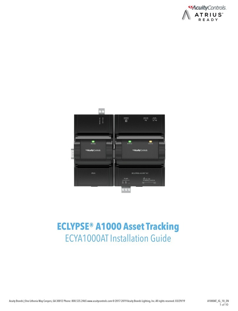
Acuity Controls nLight ECLYPSE User manual

nLight ECLYPSE®
Acuity Brands | One Lithonia Way Conyers, GA 30012 Phone: 800.535.2465 www.acuitycontrols.com © 2017-2019 Acuity Brands Lighting, Inc. All rights reserved.
User Guide

Document Revision History
£Version 1.0 - September 2017 - Release to Market
£Version 1.1 – July 2019 – Added SSO, Open ADR, nLight Air PTI
Copyright
©, Acuity Brands Inc., 2017-2019. All rights reserved.
While all efforts have been made to verify the accuracy of information in this manual, Acuity Brands is not responsible for
damages or claims arising from the use of this manual. Persons using this manual are assumed to be trained lighting pro-
fessionals and are responsible for using the correct wiring procedures, correct override methods for equipment control and
maintaining safe working conditions in failsafe environments. Acuity Brands reserves the right to change, delete or add to
the information in this manual at any time without notice.
Acuity Brands, Distech Controls, the Acuity Brands logo, and the Distech Controls logo are registered trademarks of Acuity
Brands, Inc. BACnet is a registered trademark of ASHRAE. All other trademarks are property of their respective owners.
Document Revision History
2
nLight ECLYPSE

nLight ECLYPSE
TABLE OF CONTENTS
CHAPTER 1
Introduction........................................................................................................................................................................9
Overview................................................................................................................................................................... 9
About the nLight ECLYPSE Controller........................................................................................................... 9
About the IP Protocol Suite............................................................................................................................9
About BACnet®..............................................................................................................................................9
About This User Guide ............................................................................................................................................. 9
Purpose of the User Guide ............................................................................................................................9
Referenced Documentation ...........................................................................................................................9
nLight ECLYPSE Introduction......................................................................................................................10
Network Security..........................................................................................................................................10
Intended Audience ....................................................................................................................................... 10
Conventions Used in this Document............................................................................................................10
Acronyms and Abbreviations Used in this Document............................................................................................. 11
CHAPTER 2
Internet Protocol Suite Fundamentals .............................................................................................................................12
About the Internet Network ..................................................................................................................................... 12
Internet Protocol Suite Overview ............................................................................................................................ 12
CHAPTER 3
IPv4 Communication Fundamentals................................................................................................................................13
DHCP Versus Manual Network Settings ................................................................................................................ 13
Dynamic Host Configuration Protocol (DHCP) ............................................................................................ 13
Fixed IP Address or Hostname Management .............................................................................................. 13
Networking Basics .................................................................................................................................................. 14
IP Addressing............................................................................................................................................... 14
About the Subnetwork Mask ........................................................................................................................ 14
CIDR Addressing .........................................................................................................................................15
Private IPv4 Address Ranges ...................................................................................................................... 15
Reserved Host Addresses ...........................................................................................................................15
Default Gateway ..........................................................................................................................................15
Domain Name System (DNS) ...................................................................................................................... 15
About Routers, Switches, and Hubs....................................................................................................................... 16
Connecting a Router .................................................................................................................................... 16
Network Address Translation / Firewall ....................................................................................................... 17
IP Network Segmentation ............................................................................................................................17
CHAPTER 4
IP Network Protocols and Port Numbers.........................................................................................................................18
About Port Numbers ............................................................................................................................................... 18
IP Network Port Numbers and Protocols ................................................................................................................ 18

nLight ECLYPSE
ECLYPSE Services that Require Internet Connectivity.......................................................................................... 19
CHAPTER 5
Connecting IP Devices to an IP Network.........................................................................................................................20
Connecting the IP Network ..................................................................................................................................... 20
Wired Network Cable Requirements............................................................................................................ 20
About the Integrated Ethernet Switch ..........................................................................................................21
Spanning Tree Protocol (STP).....................................................................................................................21
Connecting the Network Cable to the Controller.......................................................................................... 22
Wireless Network Connection................................................................................................................................. 22
About the 2.4 GHz ISM Band....................................................................................................................... 23
Distance Between the Wi-Fi Adapter and Sources of Interference.............................................................. 23
About Wi-Fi Network Channel Numbers ...................................................................................................... 23
Radio Signal Range ..................................................................................................................................... 24
Radio Signal Transmission Obstructions ..................................................................................................... 24
Where to Locate Wireless Adapters ............................................................................................................ 24
Transmission Obstructions and Interference ...............................................................................................25
ECLYPSE Wi-Fi Adapter Mounting Tips......................................................................................................25
Planning a Wireless Network ....................................................................................................................... 26
ECLYPSE Wi-Fi Adapter Connection Modes .............................................................................................. 28
Wi-Fi Client Connection Mode .....................................................................................................................28
Wi-Fi Access Point.......................................................................................................................................29
Wi-Fi Hotspot ...............................................................................................................................................30
Wireless Bridge............................................................................................................................................30
Wireless Network Commissioning Architectures .................................................................................................... 32
Client to Access Point Configuration............................................................................................................ 32
Client to Hotspot Configuration .................................................................................................................... 33
CHAPTER 6
First Time Connection to an ECLYPSE Controller ..........................................................................................................34
Connecting to the Controller ................................................................................................................................... 34
Controller Identification ................................................................................................................................34
Ethernet Network Connection................................................................................................................................. 35
Network Connections for ECLYPSE Controllers.......................................................................................... 35
Wi-Fi Network Connection ...................................................................................................................................... 35
Configuring the Controller....................................................................................................................................... 36
Default Credentials ......................................................................................................................................36
Using the Controller's Factory-default Hostname in the Web Browser........................................................ 36
Using the Controller's IP Address in the Web Browser................................................................................ 36
Connecting to the Controller's Configuration Web Interface................................................................................... 37
Next Steps ...................................................................................................................................................37
CHAPTER 7
Supported RADIUS Server Architectures........................................................................................................................38
Overview................................................................................................................................................................. 38
Authentication Fallback................................................................................................................................38
RADIUS Server and Enabling FIPS 140-2 Mode ................................................................................................... 38

nLight ECLYPSE
RADIUS Server Architectures................................................................................................................................. 39
Local Credential Authentication ...................................................................................................................39
ECLYPSE-Based Centralized Credential Authentication............................................................................. 40
CHAPTER 8
ECLYPSE Web Interface.................................................................................................................................................41
Overview................................................................................................................................................................. 41
Web Interface Main Menu............................................................................................................................41
Home Page .................................................................................................................................................. 42
User Profile and Login Credentials ..............................................................................................................42
Network Settings..................................................................................................................................................... 43
Ethernet .......................................................................................................................................................43
Wireless Configuration.................................................................................................................................44
Network Diagnostics ....................................................................................................................................45
BACnet Settings ..................................................................................................................................................... 47
General ........................................................................................................................................................47
Routing......................................................................................................................................................... 48
Network IP Ports .......................................................................................................................................... 48
Network MS/TP Ports .................................................................................................................................. 50
Diagnostics ..................................................................................................................................................51
User Management .................................................................................................................................................. 52
Server/Client User Configuration .................................................................................................................52
Password Policy........................................................................................................................................... 56
Radius Server/Client Settings................................................................................................................................. 56
RADIUS Server Settings..............................................................................................................................56
RADIUS Client Settings ...............................................................................................................................57
Single Sign On (SSO) Settings............................................................................................................................... 59
SSO Server Settings....................................................................................................................................59
SSO Client Settings .....................................................................................................................................60
Setting Up the SSO Functionality ................................................................................................................ 62
Certificate Authentication with SSO ............................................................................................................. 64
System Settings...................................................................................................................................................... 65
Device Information ....................................................................................................................................... 65
Updating the Firmware................................................................................................................................. 66
Export Audit Log ..........................................................................................................................................66
Location and Time .......................................................................................................................................67
Web Server Access ..................................................................................................................................... 68
Licenses.......................................................................................................................................................72
FIPS 140-2 Mode.........................................................................................................................................73
GSA IT Security Mode .................................................................................................................................75
Backup and Restore ....................................................................................................................................75
Open ADR Virtual End Node (VEN)............................................................................................................. 80
nLight ECLYPSE BACnet Points............................................................................................................................ 82
BACnet Object Mapping ..............................................................................................................................82
nLight Air PTI ...............................................................................................................................................83
CHAPTER 9
Configuring the ECLYPSE Wi-Fi Adapter Wireless Networks.........................................................................................84
Setting up a Wi-Fi Client Wireless Network ............................................................................................................ 84

nLight ECLYPSE
Setting up a Wi-Fi Access Point Wireless Network ................................................................................................ 85
Setting up a Wi-Fi Hotspot Wireless Network......................................................................................................... 86
CHAPTER 10
Securing an ECLYPSE Controller ...................................................................................................................................88
Introduction ............................................................................................................................................................. 88
Passwords .............................................................................................................................................................. 88
Change the Default Platform Credentials .................................................................................................... 88
Use Strong Passwords ................................................................................................................................ 88
Account Management and Permissions ................................................................................................................. 88
FIPS 140-2 Mode.........................................................................................................................................89
Use a Different Account for Each User ........................................................................................................ 89
Use Unique Service Type Accounts for Each Project..................................................................................89
Disable Known Accounts When Possible ....................................................................................................89
Assign the Minimum Required Permissions ................................................................................................ 89
Use Minimum Possible Number of Admin Users ......................................................................................... 89
HTTPS Certificates ................................................................................................................................................. 89
Certificates ................................................................................................................................................... 89
Additional Measures ............................................................................................................................................... 89
Update the Controller's Firmware to the Latest Release .............................................................................89
External Factors...................................................................................................................................................... 90
Install Controllers in a Secure Location ....................................................................................................... 90
Make Sure that Controllers are Behind a VPN ............................................................................................ 90
CHAPTER 11
BACnet MS/TP Communication Data Bus Fundamentals...............................................................................................91
BACnet MS/TP Data Transmission Essentials ....................................................................................................... 91
BACnet MS/TP Data Bus is Polarity Sensitive............................................................................................. 91
Maximum Number of BACnet MS/TP Devices on a Data Bus Segment and Baud Rate....................................... 92
Data Bus Segment MAC Address Range for BACnet MS/TP Devices........................................................ 92
Device Loading ............................................................................................................................................92
Data Bus Physical Specifications and Cable Requirements................................................................................... 94
Data Bus Topology and EOL Terminations ............................................................................................................ 94
Function of EOL Terminations .....................................................................................................................94
When to Use EOL Terminations ..................................................................................................................95
When to use EOL Terminations with BACnet MS/TP Thermostats ............................................................. 95
About Setting Built-in EOL Terminations ..................................................................................................... 96
Only a Daisy-Chained Data Bus Topology is Acceptable ............................................................................ 96
Data Bus Shield Grounding Requirements............................................................................................................. 97
24V-Powered Controller Data Bus Shield Grounding Requirements........................................................... 97
Using Repeaters to Extend the Data Bus............................................................................................................... 98
Device Addressing................................................................................................................................................ 100
About the MAC Address ............................................................................................................................101
BACnet MS/TP Data Bus Token-Passing Overview..................................................................................101
About Tuning the Max Info Frames Parameter..........................................................................................102
About Tuning the Max Master Parameter .................................................................................................. 102
Setting the Max Master and Max Info Frames ........................................................................................... 102

nLight ECLYPSE
Default Device Instance Number Numbering System for nLight ECLYPSE Controllers............................ 103
Adopting a Numbering System for MAC Addresses, Device Instance Numbers, and Network Numbers . 104
Setting the Controller’s MAC Address ....................................................................................................... 105
Inter-Building BACnet Connection .............................................................................................................105
BACnet/IP Broadcast Management Device Service (BBMD) .................................................................... 105
Power Supply Requirements for 24VAC-Powered Controllers............................................................................. 106
BACnet MS/TP is a Three-Wire Data Bus .................................................................................................106
Avoid Ground Lift .......................................................................................................................................106
Techniques to Reduce Ground Lift ............................................................................................................107
About External Loads................................................................................................................................. 107
Transformer Selection and Determining the Maximum Power Run Length...............................................107
24VAC Power Supply Connection .............................................................................................................108
CHAPTER 12
Modbus TCP Configuration ...........................................................................................................................................109
Controller Modbus Support................................................................................................................................... 109
Modbus TCP Device Connection.......................................................................................................................... 109
Device Addressing................................................................................................................................................ 109
About Device Addressing........................................................................................................................... 109
CHAPTER 13
Modbus RTU Communication Data Bus Fundamentals................................................................................................110
Controller Modbus Support................................................................................................................................... 110
Modbus RTU Data Transmission Essentials ........................................................................................................ 110
Modbus RTU Data Bus is Polatiry Sensitive..............................................................................................110
Data Bus Physical Specifications and Cable Requirements................................................................................. 111
Data Bus Topology and EOL Terminations .......................................................................................................... 111
When to Use EOL Terminations ................................................................................................................111
About Setting Built-in EOL Terminations ................................................................................................... 112
Only a Daisy-Chained Data Bus Topology is Acceptable .......................................................................... 112
Data Bus Shield Grounding Requirements........................................................................................................... 113
Modbus RTU Data Bus Shield Grounding Requirements..........................................................................113
Device Addressing................................................................................................................................................ 114
CHAPTER 14
Resetting or Rebooting the Controller ...........................................................................................................................115
Resetting or Rebooting the Controller .................................................................................................................. 115
CHAPTER 15
ECLYPSE Controller Troubleshooting...........................................................................................................................116
CHAPTER 16
Wi-Fi Network Troubleshooting Guide...........................................................................................................................118

CHAPTER 1
Introduction
Overview
This document describes best practices, specifications, wiring rules, and application information to implement robust and
reliable communications networks.
About the nLight ECLYPSE Controller
The nLight ECLYPSE Controller is a modular and scalable platform that is used to control a wide range of HVAC applica-
tions. It uses IP protocol to communicate on wired Ethernet networks and Wi-Fi to communication on wireless networks.
For this document, the nLight ECLYPSE will also be referred to as just ECLYPSE.
This user guide also explains how to connect to the ECLYPSE controller’s configuration interfaces.
About the IP Protocol Suite
Acuity Controls’ nLight ECLYPSE controllers use a widely used IP protocol to communicate with each other and with other
applications for control and supervision. What is commonly referred to as IP is actually a multilayered protocol suite that re-
liably transmits data over the public Internet and privately firewalled-off intranets. As integral part of our interconnected
world, this protocol is used by applications such as the World Wide Web, email, File Transfer Protocol (FTP), datashares,
and so on.
ECLYPSE controllers are able to work across geographic boundaries as a unified entity for control and administration pur-
poses.
About BACnet®
The BACnet® ANSI/ASHRAE™ Standard 135-2008 specifies a number of Local Area Network (LAN) transport types. Acu-
ity Controls’ controllers support both BACnet/IP and BACnet Master-Slave/Token-Passing (MS/TP) communications data
bus (based on the EIA‑485 medium) as a local network for inter-networking of supervisory controllers and field controllers.
About This User Guide
Purpose of the User Guide
This user guide does not provide and does not intend to provide instructions for safe wiring practices. It is the user’s re-
sponsibility to adhere to the safety codes, safe wiring guidelines, and safe working practices to conform to the rules and
regulations in effect in the job site jurisdiction. This user guide does not intend to provide all the information and knowledge
of an experienced HVAC technician or engineer.
This user guide shows you how to integrate ECLYPSE controllers into your IP network environment while enforcing stan-
dard network security practices.
Referenced Documentation
The follow documentation is referenced in this document.
£Controller Hardware Installation Guides: These documents are available on Acuity Brands website
Introduction
9
nLight ECLYPSE

nLight ECLYPSE Introduction
The nLight ECLYPSE is a modular and scalable platform that is used to control a wide range of HVAC applications. It sup-
ports BACnet/IP communication and is a listed BACnet Building Controller (B-BC).
The nLight ECLYPSE consists of an automation and connectivity server, power supply, and an nLight Interface module.
This programmable controller provides advanced functionality such as customizable control logic, Web-based design and
visualization interface (ENVYSION embedded), logging, alarming, and scheduling.
This user guide also explains how to configure the nLight ECLYPSE controller’s configuration interfaces.
Network Security
Maintaining the highest level of network security, especially when IP devices are connected to the Internet requires spe-
cially-trained personnel who are aware of the necessary techniques to ensure continued protection. This must include the
implementation of a Virtual Private Network (VPN) to connect with IP controllers over the Internet. It is also important to co-
ordinate with Information Technology (IT) department personnel the use of shared network resources.
At the first connection to an nLight ECLYPSE Controller you will be forced to change the password to a strong password
for the admin account to protect access to the controller.
Intended Audience
This user guide is intended for system designers, integrators, electricians, and field technicians who have experience with
control systems, and who want to learn about how to make a successful IP network installation. It is recommended that
anyone installing and configuring the devices specified in this user guide have prior training in the usage of these devices.
Conventions Used in this Document
This is an example of Note text. Wherever the note-paper icon appears, it means the associated text is giving a time-saving tip or
a reference to associated information of interest.
This is an example of Caution or Warning text. Wherever the exclamation icon appears, it means that there may be an important
safety concern or that an action taken may have a drastic effect on the device, equipment, and/or network if it is improperly
carried out.
Introduction
10
nLight ECLYPSE

Acronyms and Abbreviations Used in this Document
Acronym Definition
ASHRAE American Society of Heating, Refrigeration, and Air-Conditioning Engineers
AP Access Point
APDU Application Protocol Data Units
API Application Programming Interface
ASCII American Standard Code for Information Interchange
BACnet® Building Automation and Control Networking Protocol
BAS Building Automation System
B-BC BACnet Building Controller
BBMD BACnet/IP Broadcast Management Device
CIDR Classless Inter-Domain Routing
DHCP Dynamic Host Configuration Protocol
DNS Domain Name System
EOL End Of Line
FTP File Transfer Protocol
HTML HyperText Markup Language
HTTP Hypertext Transfer Protocol
HTTPS Hypertext Transfer Protocol Secure
HVAC Heating, Ventilating, and Air Conditioning
ID Identifier
IP Internet Protocol
IPv4 Internet Protocol version 4
ISP Internet Service Provider
IT Information Technology
LAN Local Area Network
MAC Media Access Control
MB Megabyte
MHz Megahertz
MS/TP Master-Slave/Token-Passing
NAT Network Address Translation
NTP Network Time Protocol
PC Personal Computer
RADIUS Remote Authentication Dial-In User Service
REST Representational State Transfer
RTU Remote Terminal Unit (for Modbus)
SSID Service Set IDentification
TCP Transmission Control Protocol
UDP User Datagram Protocol
URL Uniform Resource Locator
USB Universal Serial Bus
VPN Virtual Private Network
WAN Wide Area Network
WPA Wi-Fi Protected Access
WWW World Wide Web
Introduction
11
nLight ECLYPSE

CHAPTER 2
Internet Protocol Suite Fundamentals
This chapter describes the Internet protocol operating principles necessary to configure the IP parameters of an IP con-
troller.
About the Internet Network
The Internet is the world-wide interconnection of networks. At its root however, it is not one big network, but a group of net-
works that communicate between each other by using standard protocols and by using gateways between these networks
called routers.
The structure of the Internet is decentralized and non-hierarchical. On the Internet, all communication uses the Internet
Protocol (IP) to communicate and all connected devices are identified by their IP address. An Internet Registry allocates IP
addresses to internet service providers to be used by their users.
Data is sent across the network in packets. Each packet has a header that identifies the sender’s and intended receiver’s
IP addresses.
Internet Protocol Suite Overview
Internet Protocol (IP) is part of a multi-layered suite that together enables data communication. The following descriptions
are an overview of the IP suite protocol layers as used by IP devices:
£Physical layer (bits): This is the physical and device-to-device electrical connection layer otherwise known as Ethernet.
This layer defines:
– The requirements for the physical connection between devices (the signal medium). For example, RJ-45 connec-
tors (attached per TIA/EIA-568-A,), using Cat 5e data cable. The maximum cable length between devices is 328 ft.
(100 m) at 100 MB/s data rate.
– The electrical signal requirements for data packet transport.
– The data packet structure including data payload and the source and destination device’s MAC addresses.
In the case of Wi-Fi connected devices, the link layer is the air interface defined by the Wi-Fi standard, such as radio fre-
quencies, data rates, authentication, data channel encryption, and so on.
£Data Link layer: This layer implements the ability for two devices to exchange data with each other.
£Network layer: This layer implements the ability to connect multiple distinct networks with each other. It provides the in-
ternetworking methods that allow data packets to travel from the source device to a destination device across network
boundaries, such as a router through the use of an IP address. See About Routers, Switches, and Hubs.
£Transport Layer (segments): This layer provides end-to-end communication data stream connection between two or
more devices through a variety of protocols. However, it is the Transmission Control Protocol (TCP), the most com-
monly used internet transport protocol that is used by nLight ECLYPSE IP controllers to communicate with each other.
TCP creates a connection-oriented channel between two applications; that is to say the data stream is error-checked,
is sorted into the correct sequence (missing data packets are re-transmitted) and this data stream has a port number
for addressing a specific application at the destination host computer.
£Session layer (data): This layer implements the protocol to open, close, and manage a session between applications
such that a dialog can occur.
£Presentation layer: This layer implements the display of media such as images and graphics.
£Applications layer: This layer implements the process-to-process communications protocol that includes among other
services the BACnet/IP protocol, programming, debugging, WWW, and so on.
All of the above IP suite protocol layers must be fully functional for any two devices or controllers to communicate with
each other.
Internet Protocol Suite Fundamentals
12
nLight ECLYPSE

CHAPTER 3
IPv4 Communication Fundamentals
This chapter describes IPv4 Communication operating principles.
DHCP Versus Manual Network Settings
The following methods can be used to set the network settings:
£Manually set network settings allow precise control over the network’s configuration. This option may require an in-
depth understanding of arcane networking details – much of which is covered in this guide. See Networking Basics.
£Use the router’s DHCP setting to automatically connect devices to the network by negotiating the appropriate settings
with the device. This option may not be applicable to all networks; for example, the network administrator does not
want to use DHCP and has supplied information to manually configure the device’s IP interface.
No matter which option is chosen, it will be necessary to coordinate with Information Technology (IT) department person-
nel the use of shared network resources.
Dynamic Host Configuration Protocol (DHCP)
The Dynamic Host Configuration Protocol (DHCP) is a router feature that dynamically allocates configuration parameters
to connected devices such as IP, DNS, and default gateway addresses. Enabling DHCP on a router normally eliminates
the need to manually configure network settings on connected devices. The implementation of DHCP on most routers al-
lows a device to be assigned a fixed IP address by associating a specific IP address to a device’s MAC address.
Devices that use ECLYPSE’s internal router with the DHCP option (Hotspot/AP mode) cannot be assigned fixed IP addresses
according to the device’s MAC address.
Figure1: Typical Router Configuration to Assign a Device’s MAC Address to a Fixed IP Address
If your router supports DHCP and you have access to the router’s configuration interface, this is the most straight-forward
way to configure your network. Ensure that all devices that require a fixed IP address use a manually assigned IP address.
Fixed IP Address or Hostname Management
Why Should ECLYPSE IP controllers use a fixed IP address or use hostname Management? To program or to access an
IP controller, you must be able to connect to it. Like a postal address, a fixed IP address that is always assigned to the
same device allows you to consistently connect to and work with the same device.
An alternative to using a fixed IP address is to use the controller’s Hostname Management which allows a controller to be
identified by a nickname such as
Office_205
instead of the controller’s IP address. The hostname can be used in a Web
browser.
IPv4 Communication Fundamentals
13
nLight ECLYPSE

Networking Basics
When manually configuring the TCP/IP interface on an ECLYPSE IP controller (the DHCP option is not used), an IP ad-
dress, subnetwork mask, and a default gateway are required in the Network Settings.
IP Addressing
The most widely used internet addressing scheme is IPv4. It codes an IP address in 32 bits.
An IPv4 address is made up of two parts defined by a subnetwork mask; the network portion (which identifies a specific
network or subnetwork) and the host portion (which identifies a specific device).
About the Subnetwork Mask
Devices on the same sub-network can address IP packets to each other directly without routing. The range of IP ad-
dresses available in a sub-network is defined by the subnetwork mask. This is also called the subnetwork mask’s ‘address
space’. The subnetwork mask is coded in 32 bits as follows.
An IP packet addressed to a device on another network portion will have to be routed through the router’s WAN port as
such an address is not local. BACnet/IP broadcast discovery messages such as “Who-Is” do not pass through network
routers that separate subnetworks. This means that BACnet/IP controllers on different subnetworks will not normally com-
municate with each other.
BBMD allows broadcast message to pass through a router: on each subnet, a single device has BBMD enabled. Each
BBMD device ensures BACnet/IP connectivity between subnets by forwarding broadcast messages found on its subnet-
work to each other, and then onto the local subnetwork as a broadcast message. See BBMD Settings.
Network Class CIDR Subnetwork Mask Block
Size
Number of Subnetworks
according to the Network Type
Number of Hosts
according to the Network Type
Class A Class B Class C Class A Class B Class C
←Class A Network→
/8 255.0.0.0 256 1 16777214
/9 255.128.0.0 128 2 8388606
/10 255.192.0.0 64 4 4194302
/11 255.224.0.0 32 8 2097150
/12 255.240.0.0 16 16 1048574
/13 255.248.0.0 8 32 525286
/14 255.252.0.0 4 64 262142
/15 255.254.0.0 2 128 131070
←Class B Network→
/16 255.255.0.0 256 256 1 65534 65534
/17 255.255.128.0 128 512 2 32766 32766
/18 255.255.192.0 64 1024 4 16382 16382
/19 255.255.224.0 32 2048 8 8190 8190
/20 255.255.240.0 16 4096 16 4094 4094
/21 255.255.248.0 8 8192 32 2046 2046
/22 255.255.252.0 4 16384 64 1022 1022
/23 255.255.254.0 2 32768 128 510 510
←Class C Network→
/24 255.255.255.0 256 65536 256 1 254 254 254
/25 255.255.255.128 128 131072 512 2 126 126 126
/26 255.255.255.192 64 262144 1024 4 62 62 62
/27 255.255.255.224 32 524288 2048 8 30 30 30
/28 255.255.255.240 16 1048576 4096 16 14 14 14
/29 255.255.255.248 8 2097152 8192 32 6 6 6
/30 255.255.255.252 4 4194304 16384 64 2 2 2
IPv4 Communication Fundamentals
14
nLight ECLYPSE

CIDR Addressing
Another way to express the subnetwork mask is through CIDR addressing (Classless Inter-Domain Routing) which is writ-
ten as a slash and a number which represents the number of true bits set in the subnetwork mask. For example, the sub-
network mask 255.128.0.0 is 11111111 10000000 00000000 00000000 in binary or /9.
An IP address can be expressed with its CIDR subnetwork mask in the form of 192.168.0.0/24 for example.
Private IPv4 Address Ranges
Each IP address class has a private address range. Private IPv4 addresses cannot be routed over the Internet.
nLight ECLYPSE IP controllers will normally be assigned to a private IP address and are connected to the LAN ports of a
router, thereby keeping them behind a firewall from the internet while allowing them to freely communicate to each other
and to other trusted devices.
The following IPv4 address ranges are reserved for private networks.
Network Class IP Address Range Number of Addresses Largest CIDR Block (subnetwork mask)
A 10.0.0.0 - 10.255.255.255 16,777,216 10.0.0.0/8 (255.0.0.0)
B 172.16.0.0 - 172.31.255.255 1,048,576 172.16.0.0/12 (255.240.0.0)
C 192.168.0.0 - 192.168.255.255 65,536 192.168.0.0/16 (255.255.0.0)
Reserved Host Addresses
The first and the last IP addresses are reserved for special use on all subnetwork IP address ranges:
The first IP Address is the Network ID. Networks with different network IDs are considered to be distinct. By default, no di-
rect communication can take place between two networks that have different Network IDs. This prevents computers on
one network from being accessed by computers on another network. When one department or organization is on one net-
work, it is segregated from computers on other networks.
Last IP Address is the Broadcast Address: this is used for a specific type of network traffic that is destined to every host in
the subnetwork range of IP addresses. For example, the device’s DHCP client uses the broadcast address to find the net-
work’s DHCP server.
For Example, with a typical class C private network:
Subnetwork Mask = 255.255.255.0
Network ID = 192.168.1.0
Gateway = 192.168.1.1
Broadcast Address = 192.168.1.255
Usable IP Addresses = 192.168.1.2 - 192.168.1.254
Default Gateway
Two hosts on the same subnetwork can directly communicate with each other. When a host wants to communicate to an
IP address that is not in the subnetwork address range, the host sends the packet to the default gateway. The default gate-
way is usually the router’s IP address and is usually set in the routers administration interface. For more information about
IP routing, see About Routers, Switches, and Hubs.
Certain ECLYPSE controller services use the default gateway. See ECLYPSE Services that Require Internet Connectivity.
Domain Name System (DNS)
When you want to connect to another computer or service on the Internet (to a Website for example), rarely would you
want to use the IP address to make the connection as it would be a pain to remember the numeric IP address for each and
every site you want to visit. The Domain Name System (DNS) was created to allow internet users to take advantage of a
meaningful Uniform Resource Locator (URL) such as https://www.acuitybrands.com/ to connect to an IP address without
having to know the server’s or computer’s numerical IP address. The DNS does this by looking up the URL and providing
the numeric IP address to the requesting computer. Should the IP address of a computer/server be changed, the DNS
server can be updated with its new IP address, thereby ensuring that other networked computers can still find this com-
puter/server through its URL.
IPv4 Communication Fundamentals
15
nLight ECLYPSE

Set the DNS IP address of the Domain Name System (DNS) servers in routers and in IP controllers that have manually-
configured IP parameters. Between one and three DNS IP address is usually provided by the Internet Service Provider
(ISP). The second and third DNS addresses are for failover should the first DNS become unavailable.
If you do not know the address of your DNS server(s), try the following publicly-available DNS server addresses: primary =
8.8.8.8 and secondary = 4.4.4.4
Some ECLYPSE controller services use DNS to resolve Web addresses thereby allowing the service to operate. See
ECLYPSE Services that Require Internet Connectivity.
About Routers, Switches, and Hubs
The differences between a hub, switch, and router are discussed in the table below.
Device Type Description
Hub Every incoming data packet is repeated on every other port on the device. Due to this, all traffic is made available on all
ports which increase data packet collisions that affect the entire network, thus limiting its data carrying capacity.
Switch A switch creates a one-to-one virtual circuit that directs IP packets directly to the port that the destination computer is
connected to.
Router
Like a switch, a router learns the IP addresses of all devices connected to any of its RJ-45 ports to create a routing table. If
a data packet arrives at the router’s port with a destination IP address that is:
– Found in the router’s routing table, the router forwards the data packet to the appropriate
port for the device that has this IP address.
– For a network with a different network ID than the current network ID, the router forwards
the data packet to the uplink port where the next router will again either recognize the net-
work ID and route the data packet locally or again forwards the data packet to the uplink
port. By being exposed to traffic, a router adds to its routing table the pathways necessary
to resolve a data packet's pathway to its final destination, by passing through one or more
routers if necessary.
Connecting a Router
The way a router is connected to other devices changes its function.
1
UPLINK
234
1
UPLINK
234
ROUTER
A
ROUTER
B
Connection to use ROUTER A as a router
To
Device
To
Device
To
Device
To
Device
To
Device
To
Device
To
Device
To
WAN
1
UPLINK
234
1
UPLINK
234
ROUTER
A
ROUTER
B
Connection to NOT use ROUTER A as a router
To
Device
To
Device
To
Device
To
Device
To
Device
To
Device
To
WAN
UPLINK
Function is
Not Used
Figure2: The Way a Router is Connected Changes its Function
On some routers, the uplink port is marked as WAN (Wide Area Network) and the numbered ports are to be connected to
the LAN (Local Area Network) devices.
IPv4 Communication Fundamentals
16
nLight ECLYPSE

Network Address Translation / Firewall
A router’s uplink port provides Network Address Translation (NAT) and firewall functions.
NAT is a method to hide the private IP addresses of a range of devices (connected to LAN ports) behind a single IP ad-
dress presented at the WAN uplink port. NAT uses a mechanism to track requests to WAN IP addresses and readdresses
the outgoing IP packets on exit, so they appear to originate from the router itself. In the reverse communications path, NAT
again readdresses the IP packet’s destination address back to the original source private IP address.
Due to this tracking mechanism, only requests originating from the LAN side can initiate communications. A request from
the WAN to the router cannot be mapped into a private address as there is no outbound mapping for the router to use to
properly readdress it to a private IP address. This is why a NAT acts as a firewall that blocks unsolicited access to the
router’s LAN side.
Most routers allow you to open a port in the firewall so that WAN traffic received at a specific port number is always for-
warded to a specific LAN IP address. The standard port numbers used by ECLYPSE controllers is explained in chapter IP
Network Protocols and Port Numbers.
IP Network Segmentation
For efficient network planning, normally the IP controllers will be assigned to their own network segment of an IP network
or subnetwork. This is done as shown in the figure below.
1
UPLINK
234
1
UPLINK
234
Router for
HVAC IP
Controllers
Company
Computer
Network
Gateway Router
To
Device
To
Device
To
Device
To IP
Controller
To IP
Controller
To IP
Controller
To IP
Controller
Network
LAN
ISP Modem (Fiber, Cable, DSL)
To ISP Network
Figure3: Network Segment for HVAC IP Controllers
For certain wireless topologies, a wireless router can be used to connect to the controller. In this scenario, a wireless oper-
ator interface (laptop or tablet) can be used for commissioning as shown in the figure below.
Figure4: Network Segment for HVAC IP Controllers with a Wireless Access Point
If a wireless router is unavailable or is out-of-range, an ECLYPSE Wi-Fi adapter can be connected to an ECLYPSE con-
troller’s USB port to add wireless connectivity. See Wireless Network Connection.
IPv4 Communication Fundamentals
17
nLight ECLYPSE

CHAPTER 4
IP Network Protocols and Port Numbers
This chapter describes the IP Network Protocols and Port Numbers used by the ECLYPSE controller.
About Port Numbers
In an IP packet, a port number is an extension of the packet’s IP address and completes the destination address for a
communications session. By convention, the packet’s port number is associated with a protocol used between software
applications and is used to uniquely identify a communications endpoint for a specific application or process running on a
computer. This allows a multitude of applications to share a single physical connection to the Internet while allowing dis-
tinct communication channels between different applications.
For example, your web browser listens to port 80 on your computer to receive HTML web pages sent from a web server on
port 80.
The standard port numbers used by controllers is explained in IP Network Port Numbers and Protocols.
Sometimes, two applications might use the same port number to communicate. To sort out this conflict, the following meth-
ods can be used.
£In the configuration of some applications, the port number can be changed from its default setting. Should you change
it, you must also change it on the corresponding application also so that the port numbers will match.
£Routers have features such as port forwarding that can change an incoming packet’s port number coming from the
Wide Area Network (WAN) to another port number on the Local Area Network or vice versa.
IP Network Port Numbers and Protocols
This section lists the IP Network Protocols to communicate over IPv4 networks. The corresponding default in-bound port
number is also shown.
Service Default Port
Number (Protocol)
Description Where can this port
number be changed?
SMTP 25 (TCP) Outgoing Email server port number
DNS 53 (TCP, UDP) Domain Name Server URL lookup –
DHCP 67 (UDP) The router’s DHCP service that allows a device to auto-configure a
devices’ IP settings. –
HTTP 80 (TCP)
ENVYSION: The ENVYSION server presents system status,
trending visualization, real-time equipment visualization, schedule
configuration, alarm monitoring, and dashboard functions to a Web
browser operator interface.
Web Configuration Interface: This is the network configuration
interface for wired and wireless IP network interfaces.
See System Settings.
HTTPS 443 (TCP)
Secure ENVYSION: The ENVYSION server presents system
status, trending visualization, real-time equipment visualization,
schedule configuration, alarm monitoring, and dashboard functions
to a Web browser operator interface.
Secure Web Configuration Interface: This is the network
configuration interface for wired and wireless IP network interfaces.
See System Settings.
Radius Server 1812 (UDP) Authentication Port: This is the port on which authentication
requests are made.
IP Network Protocols and Port Numbers
18
nLight ECLYPSE

Service Default Port
Number (Protocol)
Description Where can this port
number be changed?
Radius Server 1813 (UDP)
Accounting Port: This is the port on which accounting requests are
made. This is only used to receive accounting requests from other
RADIUS servers.
Radius Server 1814 (UDP) Proxy Port: This is an internal port used to proxy requests between
a local server and a remote server. See User Management.
BACnet/IP 47808 (UDP) The BACnet over IP protocol. See BACnet Settings.
MQTT 8883 (TCP) Secure MQ Telemetry Transport. This is an internal port that
facilitates communication with the nLight Gateway.
zeroconf 5353 (UDP) This is an internal port used to access a device through the
hostname.
Unknown 5551 (TCP) System configuration (inbound/outbound)
Echo 7 (UDP) Device identification on local subnet
Rplay 5555 (UDP) Device identification on local subnet
Freeciv 5556 (UDP) nLight Protocol over IP
Unknown 33312 (UDP)
Unknown 39631 (UDP)
ECLYPSE Services that Require Internet Connectivity
In order to operate, the following out-bound services require:
£A working DNS. See Domain Name System (DNS).
£The default gateway / router to be configured. See Default Gateway.
£Internet connectivity.
The corresponding default out-bound port number is also shown.
Service Default Port Number (Protocol) Description
SMTP 25 (TCP) Outgoing Email server port number
Network Time Protocol (NTP) 123 (UDP) Used to set the controller’s real-time clock
DNS server 53 (UDP, TCP)
Used to provide URL name resolution. The controller by default
uses an internet DNS. If the local network has a DNS, set its IP
address in Network Settings.
IP Network Protocols and Port Numbers
19
nLight ECLYPSE

CHAPTER 5
Connecting IP Devices to an IP Network
An IP network requires infrastructure such as Ethernet cable, routers, switches, or Wi-Fi hotspots in order to work. The fol-
lowing topics discuss the fundamentals of such a network.
Connecting the IP Network
There are two methods to connect a device to an IP Network:
£Wired (Ethernet connection with the PRI and SEC ports).
£Wireless (when the Wi-Fi Adapter is connected to the controller).
Wired Network Cable Requirements
Wired networks use commonly available Cat 5e structural cabling fitted with RJ‑45 connectors. If you make your own patch
cable, use Category 5e cable and crimp the RJ‑45 connectors at both ends of the cable either as T568A or T568B.
Parameter Details
Media Cat 5e Cable; four (4) pairs of wires with RJ-45 Connectors (standard straight patch cable)
RJ-45 Pin Configuration Straight-through wiring. Crimp connectors as per T568A or T568B (both cable ends must be crimped the same
way).
Characteristic impedance 100-130 Ohms
Distributed capacitance Less than 100 pF per meter (30 pF per foot)
Maximum Cat 5e Cable length
between IP devices 328 ft. (100 m) maximum. See About the Integrated Ethernet Switch.
Polarity Polarity sensitive
Multi-drop
Daisy-chain (no T-connections)
ECLYPSE IP devices have two RJ-45 female RJ-45 connectors that provide IP packet switching to support follow-
on devices.
Daisy-chain limit, ECLYPSE
Controllers Up to 20 devices can be daisy-chained per network switch port.
Daisy-chain limit, VAV Controllers Up to 50 devices can be daisy-chained per network switch port.
EOL terminations Not applicable
Shield grounding Not applicable
Table1: Wired Network Cable Physical Specifications and Requirements
Bus and Cable Types Non-Plenum Applications
(Use in Conduit - FT4)
Plenum Applications (FT6)
O.D. (Ø)1O.D. (Ø)1
300 m (1000 feet), Cat 5e Yellow Jacket
Cable - Without Connectors 4.6mm (0.18in.) 4.6mm (0.18in.)
100 Crimp RJ 45 Connectors N/A N/A
Table2: Recommended Cable Types to use for the Cat 5e Cable Subnetwork Bus
1. Outer cable diameter – This does not take into account the RJ-45 connector.
Connecting IP Devices to an IP Network
20
nLight ECLYPSE
Other manuals for nLight ECLYPSE
1
Table of contents
Other Acuity Controls Controllers manuals
Popular Controllers manuals by other brands
Honeywell
Honeywell UDC100 PID OPTION MANUAL
YASKAWA
YASKAWA J1000 CIMR-JC series CHEAT SHEET
Ingersoll-Rand
Ingersoll-Rand ST400 Series Product information
Colorlight
Colorlight X1 user manual
Kohler
Kohler Decision-Maker 3500 installation instructions
Auber Instruments
Auber Instruments KIT-Cube5E Assembling Guide

