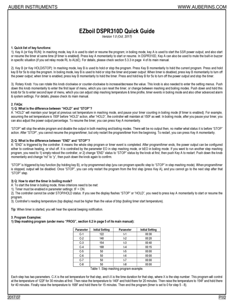
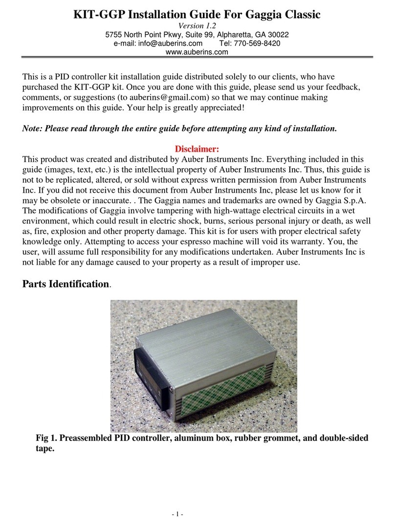
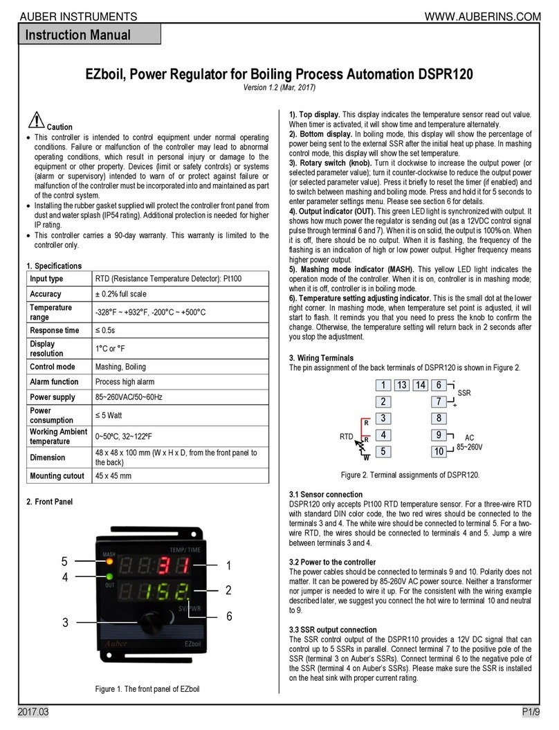
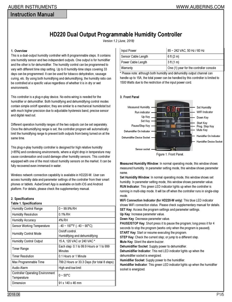
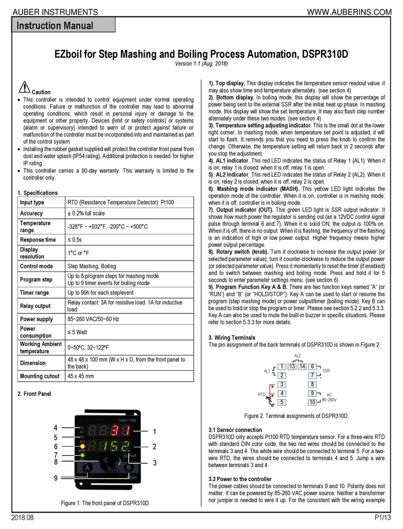
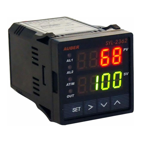
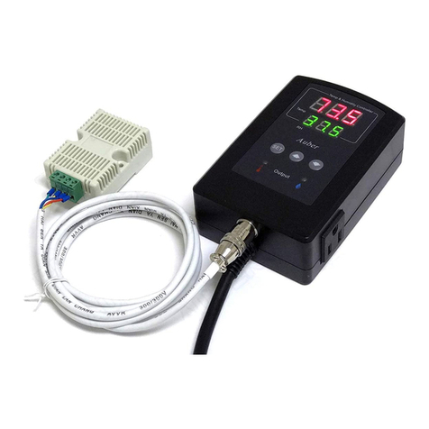
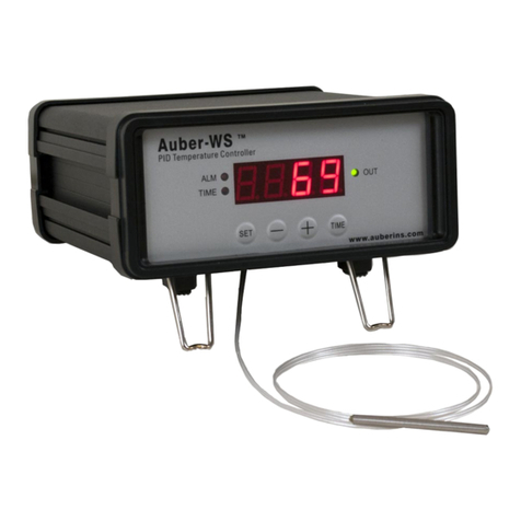
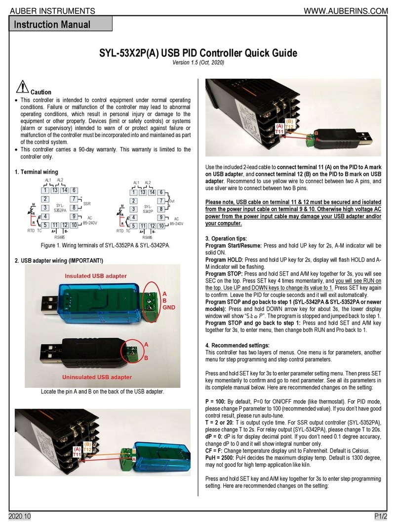
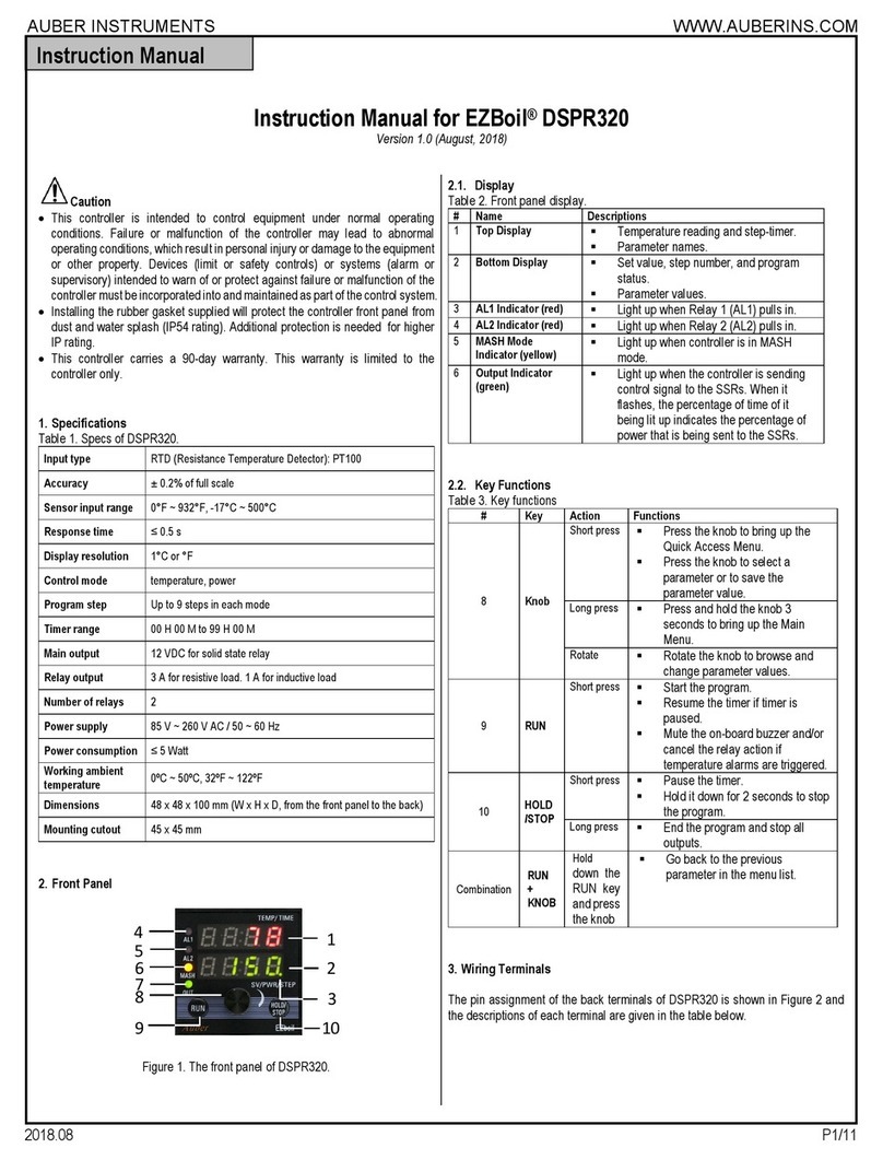
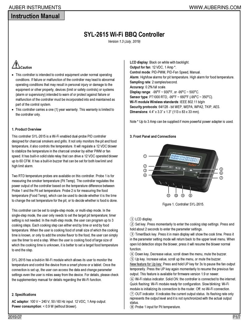
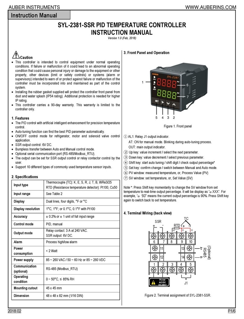
manuals.online logo
Brands
  1. Home
  2. •
  3. Brands
  4. •
  5. Auber Instruments
  6. •
  7. Controllers
  8. •
  9. Auber Instruments KIT-Cube5E User manual

Auber Instruments KIT-Cube5E User manual

AuberInstruments,Inc.  www.auberins.com
Copyright2007‐2023,AuberInstruments.AllRightsReserved.
Nopartofthismanualshallbecopied,reproduced,ortransmittedinanywaywithouttheprior,writtenconsentofAuberInstruments.Auber
Instrumentsretainstheexclusiverightstoallinformationincludedinthisdocument.

KIT-Cube5E Assembling Guide
Version0.9
(2023‐04‐21)


ThisassemblingguideonlyprovidesbasicguidanceonhowtoassemblethepartsinKIT‐CUBE5Etogether.The
personwhoattemptstoassembletheKIT‐CUBE5Eshouldhavebasicknowledgeofelectricalcircuits,can
understandwiringdiagrams,andcanusetoolssuchasamultimeter,screwdrivers,andetc.

Beforeyoustarttheassemblingprocess,pleasereadthewiringdiagramofCube5Eandunderstandeachpartis
wiringtothecircuit.

Weusethe“WiringKit”ofKIT‐CUBE5Einthisassemblingprocess.

1. Preparation
1.1. Parts
Pleaseseethepartlistincludedwiththekit.

1.2. Tools
 Flat‐endpunches(orsimilar)andasmallhammer(forremovingknockouts)
 Phillipsscrewdrivers
 Flat‐headscrewdrivers
 Adjustablewrenchorsocketwrenches
 Pliers
 Multimeter(fortroubleshooting,ifneeded)
2. Installing Components
2.1. DisassembletheEnclosure
Removethebottomplate(Figure2‐1‐a)andthebackplate(Figure2‐1‐b)byremovingthe
screwspointedbytheredarrows.

Figure2‐1‐a Figure2‐1‐b


AuberInstruments,Inc.  www.auberins.com
Page2of11

2.2. RemovetheKnockouts
Thereareafewknockoutholesontheback‐plateandoneknockoutholeonthefrontofthe
enclosurethatneedtoberemoved.PleaseseeFigure2‐2‐aandFigure2‐2‐bforthefinal
resultafteralltheknockoutsareremoved.Useflat‐endpunches(Figure2‐2‐c)andahammer
toremovetheknockoutsasshowninFigure2‐2‐d.

Figure2‐2‐a Figure2‐2‐b


Figure2‐2‐c Figure2‐2‐d


2.3. InstallComponentstotheBack‐Panel
IdentifythepowerconnectorsandtheXLRCON‐Mconnectorfromthepartsyoureceived,
installthemtotheirknockoutholesasshowninFigure2‐3(a)and(b).Pleasenotethatonly
thetwoNEMA5‐15Rsocketsaresnap‐inconnectors,otherconnectorsshouldbetightenedto
theback‐panelbyscrews.

AuberInstruments,Inc.  www.auberins.com
Page3of11

Figure2‐3‐a Figure2‐3‐b


2.4. InstallFuseBlocks
Installthetwofuseblockstotheleftsideoftheenclosure.Foreachfuseblock,firstalignthe
smallanti‐rotationtabandthescrewholewiththeholesontheenclosure(Figure2‐4‐a),then
securethefuseblockusingtheM3screwandnut(Figure2‐4‐b).Makesurethefuseblockis
notremovingaround,theninstallthefuse.


Figure2‐4‐a Figure2‐4‐b


2.5. InstallComponentstotheFront‐panel
Installthetwoselectorswitches(SW4)tothetwoAUXswitchholesonthefrontplate.Align
theselector’stwoswitchpositionswiththe“OFF”andthe“ON”markersonthefrontplate.
EachoftheSW4istightenedbytwoscrews,oneonthetopandoneonthebottomasshown
inFigure2‐5‐a.Tightenedthesetwoscrewstilltheswitchissecureandwon’trotate.

Installthepush‐buttonswitch(SW9‐UL)totheknockoutholeonthelowerfrontpanelofthe
Cubeenclosure.ThisswitchistightenedbyahexnutasshowninFigure2‐5‐a.Insertthe
suppliedwiringharness(WH‐16)tothisswitch.Youcanremovetheredwireforthenormally
closed(N.C.)pinfromthewiringharnessasshowninFigure2‐5‐b.

AuberInstruments,Inc.  www.auberins.com
Page4of11

Figure2‐5‐a Figure2‐5‐b



InstalltheEZboilcontrollertothecenterholeonthefrontplate.Installthetwowoodscrews
suppliedwithEZboilcontrollertohelpsecurethemountingbracketagainstthefrontplate
(Figure2‐5‐c).
Figure2‐5‐c



2.6. InstalltheSSRandtheHeatsink
Placethesiliconeheat‐transferpadontheheatsink(Figure2‐6‐a),thenplacethesolid‐state
relay(SSR)onthepad,usetwooftheM4screwstofixtheSSRtotheheatsink.Placethe
heatsink/SSRassemblytothetopoftheCubeenclosure,install4piecesofM6screws
suppliedwiththekittosecuretheheatsinktothetopoftheenclosure(Figure2‐6‐b).

AuberInstruments,Inc.  www.auberins.com
Page5of11


Figure2‐6‐a Figure2‐6‐b


3. Installing Wires
ImportantNotesonWiring
 Thecolorcodefor14AWGand10AWGwires
o Green:groundingwire
o White:neutralwire
o Black:hot,L1line
o Red:hot,L2line
 Threesizesofwiresareused:
o 22AWGwiresarecontrolwiresthatonlycarrysmallcurrent.
o 14AWGwireareforAUXsocketsthatcarrylessthan15Aat120VAC.
o 10AWGwiresareforthemaininput/outputthatislessthan30Aat240VAC.

3.1. InstallGroundWiresontheBack‐panel
InstallthegroundwiresasshowninFigure3‐1.UseoneofthemountingscrewsontheL14‐
30Rpowerinletasthegroundingpost.

3.2. InstallwirestotheAUXSockets
InstallthehotwireandtheneutralwiretoeachoftheAUXsockets(NEMA5‐15Rsockets)as
showninFigure3‐2.Theblackwiresontheleftarethehotwiresandthewhitewiresonthe
rightistheneutralwires.

AuberInstruments,Inc.  www.auberins.com
Page6of11

Figure3‐1 Figure3‐2


3.3. InstalltheNeutralWiresandNeutralWireBus
Useoneofthe5‐polewireconnectorsuppliedinthekitastheneutralbus.Eachofthewhite
wiresonAUXsocketshasabaretip.Insertthebaretiptothe5‐poleconnectorasshownin
Figure3‐3‐b.Installthepinconnectorofthe10AWGwhitewiretotheL14‐30Ppowerinlet
andinsertthebaretipontheotherendtothe5‐poleconnector.Identifyapieceof22AWG
whitewirefromthewiringkitandconnectittothe5‐poleconnector.

Figure3‐3‐a Figure3‐3‐b


3.4. InstallL1andL2WirestotheInputandtheOutputSockets
Identifythe4piecesoflong10AWGwiresfromthekit(ashorterblack10AWGwireisnot
neededforthisstep),andinstallthemtothepowerinletandthepoweroutletasshownin
Figure3‐4(a)and(b).TheblackwiresinthewiringkitareforL1(line1)wiresandthered
wiresareforL2(line2)wires.Pleasenotethatthewiresinstalledtothepoweroutlet(L6‐30R)
shouldhaveforkconnectors,andthewiresinstalledtothepowerinlet(L14‐30P)shouldhave
pinconnectors.

AuberInstruments,Inc.  www.auberins.com
Page7of11

Figure3‐4‐a Figure3‐4‐b


3.5. InstallWiresontheFrontPanel
Usetheother5‐polewireconnectorastheHotBus.OnthetwoAUXselectorswitches(SW4),
removeoneblockfromeachswitchbecauseweonlyneedoneblockoneach.Theblackwires
forthisstepare14AWGwireswithforkconnectorononeend,baretipontheotherend.
InstallonewiretoeachswitchblockandinsertthebaretiponotherendtotheHotBus
connector(seeFigure3‐5‐a).

Next,connecteachswitchblocktothefuseblock.Theblackwiresforthisstepare14AWG
wireswithforkconnectorononeend,femalequick‐disconnectconnectorontheotherend
(seeFigure3‐5‐b).

Onthewiringharness(WH16)ofthecontrollerswitch(SW9‐UL),thereare4pieceswiresleft,
black(LEDhot),white(LEDneutral),green(N.O.),andblue(common).Theblackandtheblue
wirefromthewiringharnessshouldbeinsertedtotheHotBus.Thewhitewirefromthe
wiringharnessshouldbeconnectedtotheEZboilcontroller’s#9,andthegreenwirefromthe
wiringharnessshouldbeconnectedtocontroller’s#10terminal.Thewiresonthewiring
harnessdon’thaveforkconnectorsinstalled.

(Note:weaddedforkconnectorstothewiresconnectedtotheEZboilcontrollerbutthisstepisnotrequiredaslong
asthewiresarefirmlyclampedbythescrewterminals.)



AuberInstruments,Inc.  www.auberins.com
Page8of11

Figure3‐5‐a Figure3‐5‐b


3.6. InstallWirestotheMainBreakerSwitch
Nowthereshouldbeashorterpieceof10AWGblackwireleftinthewiringkit.Installittothe
MainBreakerSwitch’stopleftportasshowninFigure3‐6‐a.Theninstalltheblackwire(L1)
andtheredwire(L2)fromthepowerinlet(L14‐30P)tothelowersideoftheMainBreaker
SwitchasshowninFigure3‐6‐b.Installtheredwire(L2)fromthepoweroutlet(L6‐30R)tothe
topleftportontheMainBreakerSwitch(Figure3‐6‐b).Theblackwiresshouldbeontheleft
sideoftheMainBreakerSwitchandtheredwiresshouldbeontherightside(Figure3‐6‐c).


Figure3‐6‐a Figure3‐6‐b Figure3‐6‐c


3.7. InstalltheMainBreakerSwitchtotheFrontPanel
First,installthebracketoftheMainBreakerSwitchtothefrontpanel(Figure3‐7‐a).Turnthe
breaker(aswellastheback‐panel)tothecorrectorientationandpushitintothebracketas
showninFigure3‐7‐b.Onceitisfittedin,thetwobottomtabsonthebracketshouldsnapin
andholdthebreakerinplace(Figure3‐7‐c).

InserttheshortblackwireonthebottomofthebreakertotheHotBusasshowninFigure3‐
7‐c.
AuberInstruments,Inc.  www.auberins.com
Page9of11



Figure3‐7‐a Figure3‐7‐b Figure3‐7‐c


3.8. Connectwirestothesolid‐staterelay
Installtheshortblack10AWGwiretothe#1pinontheSSRandinstalltheblack10AWGwire
fromtheL6‐30Rsockettothe#2pinontheSSR(Figure3‐8‐a).Pre‐bendthewiretoaproper
shapefirst,andtheninserttheforkconnectortothescrewterminal.Tightenthescrewso
thattheconnectorisfirmlysecured.

InstallthecontrolsignalwiresbetweentheEZboilcontrollerandtheSSR(Figure3‐8‐b).Please
notethatthecontrolsignalis12VDCandithaspolarity.Thepositivesignalfromcontroller’s
#7shouldbeconnectedtotheSSR’s#3pin.


Figure3‐8‐a Figure3‐8‐b


3.9. ConnectwirestotheEZboilcontroller
AuberInstruments,Inc.  www.auberins.com
Page10of11

Installthethreewiresfromtheprobeconnector(XLRCON‐M)totheEZboilcontrolleras
indicatedbythestickeronthecontroller.Thetwowiresofthesamecolorshouldbe
connectedto#3and#4,theotherwireto#5asshowninFigure3‐9.

Identifythe22AWGwhitewireontheneutralbus.Connectitsforkconnectortothe#9pin
onthecontroller.Ensurethatanotherwhitewirefromtheswitchwiringharnessisalsofirmly
installedtothe#9pinonthecontroller(Figure3‐9).


Figure3‐9 Figure3‐10

3.10. ConnectAUXSocketsandFuseBlocks
Connecttheblack14AWGwiresontheAUXsocketstothecorrespondingfuseblocksas
showninFigure3‐10.

Atthispoint,allthepartsandwiresshouldhavebeeninstalled.

4. Inspection and Assemble the Cube
4.1. Inspection
Checkforanylooseorfreewires,oranymismatchofthewirecolorbetweenthewiringin
yourCubeunitandtheimageinFigure4‐1.Checkthewiringagainstthewiringdiagram.
AuberInstruments,Inc.  www.auberins.com
Page11of11

Figure4‐1.

4.2. Installthebackpanelandthebottomcover.
InstallthebackpanelfirstbytightenthetwoscrewsoneachsideasshowninFigure4‐2.Then
putthebottomcoverbackandinstallthe8screws.

Figure4‐2

(End)

AuberInstruments,Inc.5755NorthPointParkway,Suite99,Alpharetta,GA30022,USA.
www.auberins.com
E‐mail:[email protected]Tel:770‐569‐8420
Copyright2007‐2023,AuberInstruments.AllRightsReserved.
Nopartofthismanualshallbecopied,reproduced,ortransmittedinanywaywithouttheprior,writtenconsentofAuberInstruments.Auber
Instrumentsretainstheexclusiverightstoallinformationincludedinthisdocument.



Other Auber Instruments Controllers manuals
Auber Instruments HD330 User manual

Auber Instruments

Auber Instruments HD330 User manual

Auber Instruments HD220-W Instructions and recipes

Auber Instruments

Auber Instruments HD220-W Instructions and recipes

Auber Instruments EZboil DSPR320 User manual

Auber Instruments

Auber Instruments EZboil DSPR320 User manual

Auber Instruments SYL-2381-SSR User manual

Auber Instruments

Auber Instruments SYL-2381-SSR User manual

Auber Instruments TH220A User manual

Auber Instruments

Auber Instruments TH220A User manual

Auber Instruments SYL-3615 User manual

Auber Instruments

Auber Instruments SYL-3615 User manual

Auber Instruments AW-SYL-2352 User manual

Auber Instruments

Auber Instruments AW-SYL-2352 User manual

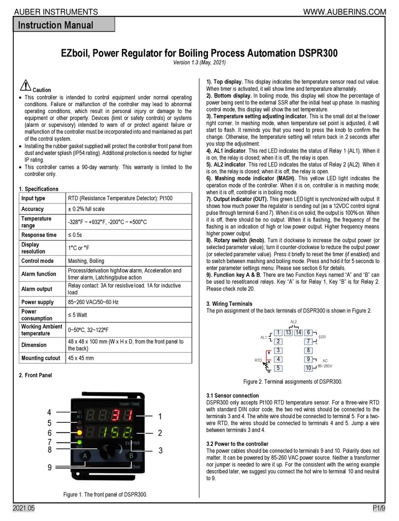
Auber Instruments DSPR300 User manual

Auber Instruments

Auber Instruments DSPR300 User manual
Auber Instruments WS-1500EPM Administrator Guide

Auber Instruments

Auber Instruments WS-1500EPM Administrator Guide

Auber Instruments EZboil DSPR310D User manual

Auber Instruments

Auber Instruments EZboil DSPR310D User manual

Auber Instruments KIT-CUBE2S User manual

Auber Instruments

Auber Instruments KIT-CUBE2S User manual

Auber Instruments RDK-300B User manual

Auber Instruments

Auber Instruments RDK-300B User manual

Auber Instruments WS-1500A Administrator Guide

Auber Instruments

Auber Instruments WS-1500A Administrator Guide

Auber Instruments SYL-3615 User manual

Auber Instruments

Auber Instruments SYL-3615 User manual

Auber Instruments EZboil DSPR120 User manual

Auber Instruments

Auber Instruments EZboil DSPR120 User manual

Auber Instruments Cube 5E User manual

Auber Instruments

Auber Instruments Cube 5E User manual

Auber Instruments EZboil DSPR310D User manual

Auber Instruments

Auber Instruments EZboil DSPR310D User manual

Auber Instruments Auberins KIT-GGP User manual

Auber Instruments

Auber Instruments Auberins KIT-GGP User manual

Auber Instruments HD220 User manual

Auber Instruments

Auber Instruments HD220 User manual

Auber Instruments SYL-2615 User manual

Auber Instruments

Auber Instruments SYL-2615 User manual

Auber Instruments SYL-53 2P Series User manual

Auber Instruments

Auber Instruments SYL-53 2P Series User manual

Auber Instruments SYL-2362B User manual

Auber Instruments

Auber Instruments SYL-2362B User manual

Auber Instruments DSPR400 User manual

Auber Instruments

Auber Instruments DSPR400 User manual

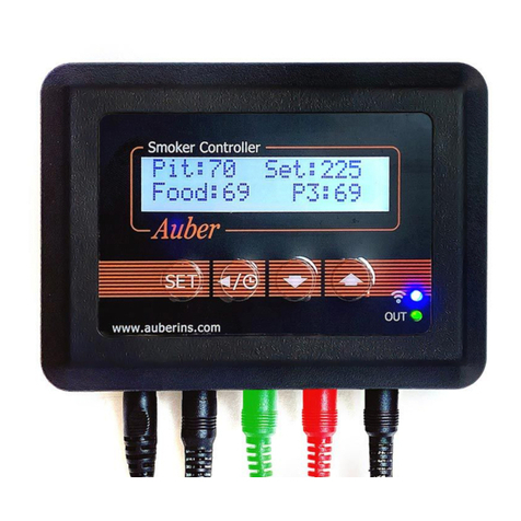
Auber Instruments KIT-RSPb User manual
Auber Instruments

Auber Instruments KIT-RSPb User manual

Popular Controllers manuals by other brands
RWE ISR2 quick start guide

RWE

RWE ISR2 quick start guide

Allen-Bradley Bulletin 161 B Series user manual

Allen-Bradley

Allen-Bradley Bulletin 161 B Series user manual

Honeywell CENTRA LINE EAGLEHAWK Installation & commissioning instructions

Honeywell

Honeywell CENTRA LINE EAGLEHAWK Installation & commissioning instructions

Salto BLUEnet CUC1B0 Series installation guide

Salto

Salto BLUEnet CUC1B0 Series installation guide

Vega VEGATOR 111 operating instructions

Vega

Vega VEGATOR 111 operating instructions

HDL Buspro HDL-MSM.431 user manual

HDL

HDL Buspro HDL-MSM.431 user manual

Evco EV3 WEB Installer manual

Evco

Evco EV3 WEB Installer manual

Motorline professional SIGMA X User& installer's manual

Motorline professional

Motorline professional SIGMA X User& installer's manual

DriSteem Vapor-logic 4 Installation and operation manual

DriSteem

DriSteem Vapor-logic 4 Installation and operation manual

Emerson CASH VALVE B Series Installation, operation and maintenance instructions

Emerson

Emerson CASH VALVE B Series Installation, operation and maintenance instructions

Asco WSDU-M Series Installation and maintenance instructions

Asco

Asco WSDU-M Series Installation and maintenance instructions

AUMA SV 05.1 Operation instructions

AUMA

AUMA SV 05.1 Operation instructions

Elan V883 installation manual

Elan

Elan V883 installation manual

Caen V793 Technical information manual

Caen

Caen V793 Technical information manual

Euroterm 2604 Installation and wiring instructions

Euroterm

Euroterm 2604 Installation and wiring instructions

Toshiba Prosec T-Series Operation manual
Toshiba

Toshiba Prosec T-Series Operation manual

Seeley MagIQtouch Original instructions

Seeley

Seeley MagIQtouch Original instructions

JP Hobby ER-120 V1 instruction manual

JP Hobby

JP Hobby ER-120 V1 instruction manual

manuals.online logo
manuals.online logoBrands
  • About & Mission
  • Contact us
  • Privacy Policy
  • Terms and Conditions

Copyright 2025 Manuals.Online. All Rights Reserved.