ACUVANCE EXSTRAIGHT User manual

CAUTION
Introduction
Thank you for purchasing the EXSTRAIGHT. To get
the best from your EXSTRAIGHT, please read this
manual carefully. After reading it, be sure to keep it
in a convenient location.
Features
• The state-of-the-art, ultra-compact power MOSFET <SOP*1> is employed, achieving a power-on resistance value (FET standard)
of 0.25mΩ.
• The MPRS system*2is adapted to a large current circuit. The ultra-small controller minimizes heat generation and significantly
reduces loss of battery energy.
• The current limiter setting enables smooth start-up and improves run-time.
• The brake rate adjustment enables faster braking.
*1SOP : Today's mainstream system developed by KEYENCE for the first time as a surface-mount package and speed controller.
*2 MPRS (Metal Plate Radiation of heat Structure) : Hybrid structure which conducts current not through a copper foil but through a metal plate on the PC board.
It allows the best configuration with the FET.
The following symbols alert you to
important messages. Be sure to read
these messages carefully.
WARNING
CAUTION
NOTE
Instructions to prevent accidents or product damage
Additional information on proper operation
Precautions
1. Ni-Cd or Ni-MH battery
WARNING: To prevent fumes, fire, and burns
Improper use of the battery is very dangerous. The battery must be handled carefully. Incorrect wiring or short-circuiting of the
cables may cause fire or fumes. Before connecting or disconnecting the battery to or from the ESC, be sure to turn off the
ESC's power switch. Do not charge the battery while it is connected to the ESC. When the battery is not in use, disconnect it
from the ESC or charger, and store it in a location with no wires or screws.
2. Connection of silicone cables
WARNING: To prevent fumes, fire, and burns
A faulty wiring or electrical contact (short-circuit) will damage the amplifier and may generate fire or smoke. In addition, both the amplifier
and battery may become irreparable. Refer to the electrical wiring diagram (note the colors and positions) and arrange the wiring properly.
Also, make sure to remove the battery before starting the wiring operation in order to prevent ignition or other accidents.
3. Mounting motor
WARNING: To prevent fumes, fire, and burns
Make sure to attach the provided shottkey diode and condenser to the motor. When the motor revolves, excessive voltage (surge
over-voltage) is generated, which may damage the amplifier under some circumstances. Mounting the shottkey diode and
condenser will control the voltage (surge voltage) applied to the amplifier. In addition, it will enhance the efficiency of the motor
revolution. Refer to the section of "Wiring and names of each part" on the following page and perform the mounting procedure
properly. Note that the shottkey diode has polar characteristics. Be sure to mount the shottkey diode in proper orientation.
4. Heat sink (Radiating fin)
WARNING: To prevent fumes, fire, and burns
Electricity flows through the metallic part at the top of the ESC. Therefore, do not allow wiring cables, other metallic parts and the carbon
chassis to make contact with the ESC. When a heat sink is attached, electricity flows through the heat sink. Exercise the same precautions.
5. Proper operation
CAUTION: To prevent accidents and product damage
Do not modify the ESC. Use it only for its intended purpose.
Keep the ESC away from flames or heat. Avoid splashing any liquid, such as water, on the ESC.
6. ESC mounting orientation
Except for at the outer side of the car, mount the ESC with its terminal side oriented to prevent the cable connector (terminal)
side and PC board from any damage caused by car bodies contacting, collision, or turnover.
Ultra-small digital speed controller Instruction Manual
Instructions to prevent serious injury
: To prevent accidents and product damage
NOTE

0
A=100
A=50
A=0
100%
(No limitation)
50%
0%
WARNING: To prevent fumes, fire, and burns
Current limiter
The trimmer turns within a range of 240 degrees. Do not force it past this range.
Current limiter trimmer (0 to 100%)
The " " mark in the trimmer indicates
the set value.
Current
limiter value
Time
As illustrated on the right, changing the current limiter value changes the
maximum current capacity. When the road surface is slippery, lower the
limiter value (close to 0%). When you need high torque, raise the value. If
you set the current limiter value to 100%, the current limiter function
does not work and maximum torque can be produced. If you set the value
to 0%, the current is limited to the minimum value and some motors may
revolve at a slow speed. Set the value according to your needs.
Brake adjustment function
★
Adjusting the brake to match the road surtace enables smooth running
The trimmer turns within a range of 240 degrees. Do not force it past this range.
Current limiter trimmer (0 to 100%)
Brake adjustment trimmer (0 to 70% max)
The " " mark in the trimmer indicates
the set value.
In normal mode, the minimum brake level can be changed by setting the
brake adjustment trimmer. When the trimmer is set to minimum, the
brake level changes linearly with the trigger level. When the trimmer is set
to maximum, the minimum brake level is 70% of the maximum brake
level. If you need strong brakes, gradually increase the setting value until
you find a suitable level. Turning on the power switch while holding down
the SET switch and then releasing the SET switch activates the neutral
brake mode. The neutral brake level is the value specified with the brake
adjustment trimmer. (The neutral brake mode is reset when you turn the
A-01B off and on again without holding the SET switch. The operation
mode setting is not retained.)
Brake trigger level : The level of the throttle opening between the
neutral and brake-high point.
Dash power mode
★When a car is started, the current limiter can be canceled only with the first throttle operation if you want to make a quick start.
1.
Turn the transmitter on and hold down the SET switch for approximately 5 seconds. The LED flashes. (Same as in setup mode.)
2. Wait until the LED stops flashing. (Approximately 10 seconds) The dash power mode is set.
If any noise interferes with the above setting procedure, the ESC may mistake the noise for throttle
operation and may not set the dash power mode.
Mounting heat sink (Radiating fin) Tips
Electricity flows through the radiating plates. If you mount a radiating fin, the
electricity might flow through it. Do not allow other cables and metallic parts to
make contact with the radiating fin.
★
If you run a car under normal conditions, the radiating fin is not
necessary. When running a car under a blazing sun or if you are using
a high-torque motor, mounting the radiating fin enables a more
stable run. Mount the radiating fin as described below:
1. Remove an aluminum top sticker at the top of the ESC housing.
2. A metallic plate is exposed.
3. Remove dust from the plate surface.
4. Attach the double-sided tape (included) to a radiating fin.
(Be sure to always use thin double-sided tape.)
5. Securely attach the heat sink to the metallic plate of the ESC.
(To improve radiation, apply 2-gel type epoxy resin adhesive instead of the
double-sided tape. Knead the gels well and apply a light coat of it to the heat
sink. Attach the heat sink to the metallic plate and fix them until the adhesive
dries. Note that you cannot remove the heat sink once you attach it.)
★Limiting the maximum current to the motor prevents a skid and improves battery efficiency.
NOTE
NOTE
NOTE
Current
(A)
0%
100%
Approx.
70%
35%
Brake adjustment trimmer:
At minimum
Brake adjustment trimmer:
At maximum
Brake adjustment trimmer:
At minimum
Brake adjustment trimmer:
At maximum
Brake
level
Brake trigger
level(※)
Neutral Brake Brake-high point
Approx.
70%
35%
0%
100%
Brake
level
Brake trigger
level(※)
Neutral Brake Brake-high point
Normal mode
Neutral brake mode
※
(1) About the setting of the braking point:
When the braking point is set to a value that is too low, the brake feels
weak.
• For a Propo radio control with ABS, turn off the ABS first, set the braking
point, and then turn on the ABS again.
• When you have problems with the setting, reverse the current setting of
the reverse switch on the throttle side of the transmitter, and then adjust
the amplifier settings again.
(2) About the setting for the braking rate:
Adjusting the braking rate will enable smoother travel motion. Use this
feature when faster braking performance is required with a heavy car body,
etc. First, turn the braking adjustment trimmer to the leftmost position,
and then gradually turn it to the right to increase the initial strength of the
brake actuation. Adjust the braking rate to the optimal point while
checking the travel motion. (Note that the maximum braking power will
not change.) When the neutral braking setting is selected, the setting is
adjusted so that the braking is always set to ON when the car is put in
neutral. This feature displays its force when traveling on a course requiring
high cornering abilities. Use this feature as required.
(3) About the setting of the high point:
The setting of the throttle high point can be adjusted normally at full
throttle. However, the setting can also be adjusted short of full throttle (60
to 80%) to change the sensation of operation (acceleration feel). Adjust
the setting at the point with optimal operational feeling.

1.
2.
3.
4.
5.
6.
7.
8.
9.
10.
Part names and wiring
WARNING: Precautions to prevent smoke, fire, or an explosion
Be extremely careful to observe the correct polarity for the wiring of the battery and Schottky diode. Be sure to install a capacitor
and Schottky diode to the motor. If you do not, the ESC may malfunction.
Receiver connector
Usage
Setup
★Perform each setup procedure within 10 seconds after the LED begins flashing. (This is because the unit is automatically reset after 10 seconds.)
Ensure that the ESC's power switch is turned off.
To lock a car, eliminate any driving force on the tires by disconnecting the motor cable, etc.
Turn the transmitter on. Reset each throttle function (throttle curb, ABS, trimmer point, etc.) to the normal position.
Turn the ESC on.
Hold down the SET switch for approximately 5 seconds.
The LED indicator flashes. (The ESC enters setup mode.)
Set the transmitter throttle to "Neutral", and then press the SET switch once.
The LED indicator flashes faster.
Set the transmitter throttle to "High point" (at 90% of full throttle), and then press the SET switch once.
Setup is completed.
With a correct setting, the LED will light at neutral, turns off as the throttle is gradually opened, and light again at high point and
brake point. If the setting of the transmitter interferes the correct setting, repeat the procedure after setting the reverse switch of
the transmitter's throttle to the opposite side. See also the separate sheet"Key to setting".
Solder the terminals with care so as not to damage the internal circuitry. Insulate points
where the conductor is exposed, where wires have been stripped or soldered, using tape or
heat shrink tubing. Otherwise, a short may occur.
If you use a motor with less than 13 turns, you
should attach a schottky diode to the left side of
motor. (It reduces heat generated from the
amplifier, and improves efficiency.)
Setup confirmation
With no connector
Load on the amplifier is reduced.
Pay attention to the polarity
when reattaching.
NOTE NOTE
LED lamp
Current restraint trimmer
Brake adjustment trimmer
Set switch
Power switch −MOT
−BAT
+BAT
+MOT
Rx connector
Capacitor
Motor
indicates points to be soldered.
Aluminum shield
Noise reduction capacitor
■■
Connected to battery
Connected to the motor
FET servo power line (yellow)
★Schottky diode
Battery
Motor
Battery
OFF
ON
With a connector
(Pay attention to the polarity)
Be sure to remove the batteries before modifying the wiring. Be extremely careful that the wires' polarity is correct.
Note that we do not repair servos and receivers.
WARNING: Precautions to prevent smoke, fire, or an explosion
This type is attached stopper to prevent
from falling out at the connector side
(resin part), not connecter pin side (metal
part). Pull out the cable while a convex
part of the connector is raised slightly
using needle, cutter or sharp thing
when you pull out the cable. Insert the
cable untill there is a sound of crack
while turning the side with
connector pin (metal part)
up when you insert the
cable.
FUTABA, New KO
New SANWA (Z connector), JR
The connector can be
used without change.
Cut
here Cut
here
Manufacturer
of your receiver
Shape of
connector insert
port
(receiver side)
Avoid reverse
insertion.
Avoid reverse
insertion.
Wiring
Former SANWA, Former KO
NOTE
This side should be turned up.
Be careful of treatment at the time of using a cutter.

Power supply
Maximum current
ON resistance
Dimensions
Weight (ESC unit)
Regulator for receiver/servo
PWM frequency
6-cell or 8-cell, Ni-Cd or Ni-MH battery
Max. current of battery
0.00025 ohm (FET Data)
30.6 (W) x 26.1 (D) x 13.1 (H) (except for terminal)
17 g
5.8 V output, 1 A max. (when 7.2 V is input)
2930 Hz
WARNING: To prevent fumes, fire, and burns
When using a high-torque servo
Be sure to remove the battery and external power supply before changing the wiring. Ensure that the polarity of the wiring is
correct. Incorrect polarity may cause a malfunction in the ESC, receiver, and servo.
When using a high-torque servo, the capacity of the BEC power supply may become insufficient. Install the provided resistor for the
high-torque servo as shown in the wiring diagram below.
Troubleshooting
Symptom
Brake fails.
Motor and servo both
do not work.
Motor does not work,
but servo works.
ESC gets too hot.
Acceleration is decreased.
Car behaves incorrectly.
Cause
Cannot set "High point" Improper setting of ESC
Improper transmitter setting
Improper setting of ESC
Improper transmitter setting
Bad contact with battery
Improper wiring of receiver
Receiver failure
Transmitter failure
ESC failure
Improper setting of ESC
Motor failure
Bad contact with battery
Bad contact with receiver connector
ESC failure
Input voltage is too high
Insufficient cooling
Driving load is too high
Improper ESC setting
Current limiter value is too low
Failure in motor capacitor
Bad position of receiver
Transmitter/receiver failure
Incorrect wiring
Remedy
Reset transmitter throttle setting to normal before setting "High point". Set "High point" position at 90% of full throttle.
Correct transmitter throttle setting.
Reset transmitter brake setting to normal before setting "Brake point". Set "Brake point" position at 90% of full throttle.
Correct transmitter brake setting.
Check that contact with battery is good.
Check that wiring of receiver and servo is correct.
Replace crystal or request repair.
Replace crystal or request repair.
Request repair.
Setup ESC again from the beginning.
Replace motor.
Check that battery and cables are properly connected.
Confirm whether the Rx connector pin is broken or loose.
Request repair.
Use 6-cell power supply.
Attach radiating fin to improve air flow and heat radiation.
Adjust driving system.
Schottky diode failure Confirm whether the schottky diode connected between the body and the motor is loose or damaged.
If the diode appears to be damaged, exchange it.
Setup ESC again from the beginning.
Increase current limiter value.
Schottky diode failure Confirm whether the schottky diode connected between the body and the motor is loose or damaged.
If the diode appears to be damaged, exchange it.
Replace motor capacitor.
Keep receiver as far from battery or ESC as possible.
Request repair.
Make silicone cables as short as possible.
If a failure should occur within three months of the date of purchasing the ESC,
write the symptoms of the problem and the working condition on a separate sheet.
Request a repair of the ESC from either the distributor where you purchased the
ESC or from ACUVANCE (Technical Service Department).
Date of
purchase
Item
Manufacture
no.
Costomer's
address
Telephone no.
Name
Warranty
term
Ultra-small digital speed controller
1. The part that can be repaired is as follows. Internal electronic circuit
(Damage caused by incorrect connection or running operation is not covered by the warranty.)
2. Note that repairing the ESC is impossible in the following cases.
When opening the ESC housing.
When using a power supply other than the specified 6-cell or 8-cell battery.
When modifying the wiring in order to use a separate power supply.
3. KEYENCE assumes no responsibility for damage of the receiver or servo caused by incorrect connection
of the ESC.
4. Note that if the repair card is not filled out, repair and return of the ESC may be delayed.
EXSTRAIGHT ...
ー
TEL ( )
3 months from
the date of purchase
Warranty
Repair regulations Request card for repair
1. Symptom (Condition)
Please describe condition of the ESC as detailed as possible.
Please fill in the blanks below.
Name
Address
Tel. No.
:
:
:
3. Shop where you bought the ESC
2. Your equipment
Motor Turn No.
Description Maker Model No.
(1) Since the resistor element has no polar characteristics (positive/negative), there
is no need to consider the wiring orientation.
(2) Make sure to isolate the soldered points using a shrinkable tube after applying
solder.
(3) Although the resistor generates some heat after a long travel motion, this is not
an abnormal phenomenon.
(4) Make sure to install the resistor, because it is designed to protect the servo.
Perforated line
NOTE
Specifications
Note that if the date and location of the EXSTRAIGHT purchase are not entered on the warranty card,
you will be charged for repairs even within the warranty term.
7F, Shin-Osaka Marubiru Annex 1-18-22 Higashinakajima Higashiyodogawa-ku
Osaka 533-0033 Japan. E-mail support@acuvance.co.jp
Battery Voltage:
F-1
V
Capacity: mAh
Receiver
Transmitter
Servo
R/C Car
Others
Touring Car
Buggy (4WD)
Buggy (2WD)
Receiver
Soldering
Protective resistor for servo (2W/0.47Ω)
Servo
RX cable on the servo side: red (orange) line Power-supply line for FET servo (yellow)
Technical Service Dept.
0413-2
Other ACUVANCE Controllers manuals
Popular Controllers manuals by other brands
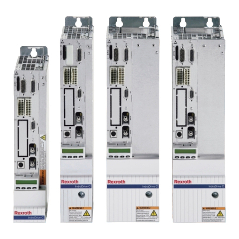
REXROTH
REXROTH IndraDrive C Series Project planning manual
BridgIoT
BridgIoT Geasy MK6 instruction manual

AUTOFLAME
AUTOFLAME Mk8 MM Installation and commissioning guide
Linear Technology
Linear Technology DC1427A quick start guide

ATTO Technology
ATTO Technology FibreBridge 7500 Getting started guide

IOTA
IOTA ETS-STEP instruction manual
