Phenix LD60A User manual

LD60A
User’s Manual
LIQUID DIELECTRIC TEST SET
MODEL NUMBER LD60A
VERSION 3.4
Copyright © Phenix Technologies, Inc.
Rev 2/28/2018
Rev 8/26/2019 (format)

LD60A
TABLE OF CONTENTS
Section Number
DANGER / GENERAL SAFETY PRECAUTIONS
DESCRIPTION 1
SPECIFICATIONS 2
INSTALLATION AND GROUNDING INSTRUCTIONS 3
OPERATING INSTRUCTIONS 4
CALIBRATION 5
ELECTRICAL SCHEMATICS 6
MAINTENANCE AND TROUBLESHOOTING 7
PARTS LIST 8
PARTS ORDERING INFORMATION 9
RETURNED MATERIAL 10
CUSTOMER COMMENTS / SUGGESTIONS 11

LD60A
DANGER / WARNINGS
WARNING !!
Complete Grounding of this unit is necessary for
the safe operation of this equipment. Disconnect
inputs before ungrounding this equipment

LD60A
GENERAL SAFETY PRECAUTIONS
This equipment can produce POTENTIALLY LETHAL VOLTAGES!
Improper operation or test practices may result in injury or death to the
operator or surrounding personnel.
The operation of High Voltage test equipment should only be performed by
personnel familiar with HIGH VOLTAGE testing and safety procedures. The
operator of this equipment must be aware of all hazards associated with High
Voltage testing. The operator is responsible for himself and others in close
proximity of the testing area.
Some General Safety Practices for working with High Voltage Test Equipment
have been listed below for your reference.
•Become familiar with your instrument before performing an actual test
•Know your work area, check that all circuits are de-energized and locked
out.
•Never work alone; always work with another qualified worker.
•Mark off entire work area with barriers and warning tape.
•Make all personnel aware of your testing activities.
•Be aware of dangerous conditions that may arise from energizing a test
specimen.
•Never modify test equipment, modifications to equipment could introduce
an unknown hazard or hinder a designed-in safety feature.
•DO NOT operate damaged equipment. Remove power, and do not use
the equipment until safe operation can be verified by service-trained
personnel.
Phenix Technologies, Inc. assumes no liability for unsafe or improper use of test equipment.

LD60A
1-1
SECTION 1: DESCRIPTION
The Liquid Dielectric Test Set, Model LD60A, is designed to test and measure the dielectric
breakdown of insulating oil used in transformers, capacitors, bushings, etc. in accordance to
ASTM D877 and ASTM D1816. The standard test set also satisfies the requirements of IEC,
VDE, and BS standards.
The test set is a portable type built into a rugged carrying case. The Control Panel is below the
cover with the voltmeter and the high voltage test compartment. The test compartment is
provided with a see-through lid interlocked to the test circuit with a limit switch to ensure full
safety during operation.
As options, the test set can be supplied with two different kinds of test cells, either TC/VDE test
cell with VDE electrodes according to ASTM D1816, or TC/DE test cell with 1-inch flat electrodes
according to ASTM D877. Other cells are available upon request.
SAFETY FEATURES
•Center tapped high voltage transformer.
•The test cell is isolated from the supply when the protective lid is raised.
•Fast acting relay in series with the high voltage winding and the test cell ensures immediate
cutout at flashover above specified current levels.
•Control lamp indicating AC power on.
•Control lamp indicating failure.
•Fast acting fuses are located both in the input to the test set and in the primary of the high
voltage transformer.
OTHER FEATURES
•Input switch, fuse, and power indicator lamp.
•Motorized output voltage control from 0 to 60,000 volts with three selectable speeds of 500,
2000 and 3000 volts per second.
•Single range memory voltmeter connected across transformer primary calibrated to output
voltage level records breakdown voltage for the test sample.
•The test compartment is provided with a 115-volt outlet for convenient plug-in of motor driven
stirrer when testing to ASTM D1816 standards.

LD60A
2-1
SECTION 2: SPECIFICATIONS
Input Voltage/Current Single Phase, 120 Volts at 60 Hz, 5 Amps
Output Voltage/Power 0-60,000 Volts at 500 VA (momentary), Maximum Voltage to
Earth is 30,000 Volts
Rate of Rise Selectable—500/2000/3000 Volts/Second
Memory Voltmeter Scale of 0-60,000 Volts, Accuracy 1% of Full Scale
Dimensions 21 1/4” W x 16 3/4” D x 13 3/4” H
(540 mm W x 426 mm D x 350 mm H)
Weight 55 lbs. (25 kg)

LD60A
3-1
SECTION 3: INSTALLATION AND GROUNDING INSTRUCTIONS
Setup:
1. Place the test set on a table or similar flat and stable surface.
2. Make sure that the test set is level.
3. Open the cover.
4. Check that your input voltage corresponds with the input of the test set.
5. Check that your supply outlet provides a ground.
6. Connect the power cord to the outlet.
7. The test set is now installed and ready for operation.

LD60A
4-1
SECTION 4: OPERATING INSTRUCTIONS
LD60A (Shown with Cover removed)
1. AC Power Cord connector. CAUTION: Facility power must be grounded.
2. Meter displays rise in voltage 0-60 kV. Operator selects rate of rise by turning dial to 500,
2000, or 3000 Volts.
3. Failure light illuminates if test fails.
4. Press to Start or to Stop.
5. Remote Mode. Press to select OFF or ON. If ON, controls are available on the optional
Tablet or Bluetooth device (if enabled; See instructions below).
6. Device Pair. Press to select Pair that permits Bluetooth connection. If connected, BT Power
light illuminates (location 8).
7. CB1 indicator. If button is up, indicates that CB1 is open. Press to close.
8. BT Power. When connected, Bluetooth LED illuminates.
9. Test Compartment.
1
2
3
7
5
6
9
8
4

LD60A
4-2
OPERATING INSTRUCTIONS
Operation
The test set is fully automatic. To gain test data, follow these procedures:
1. Place the prepared test cell in the test compartment;
2. Set voltage rate of rise switch to correct position;
3. Close test chamber lid;
4. Switch to start position.
It will automatically raise the voltage to the breakdown level, indicate “failure,” and the breakdown
level can be read on the voltmeter.
The Android tablet (Option) provides a convenient remote mode control option using Bluetooth
technology.

LD60A
4-3
OPERATING INSTRUCTIONS
LD60A Android App (Remote Mode) (OPTION)
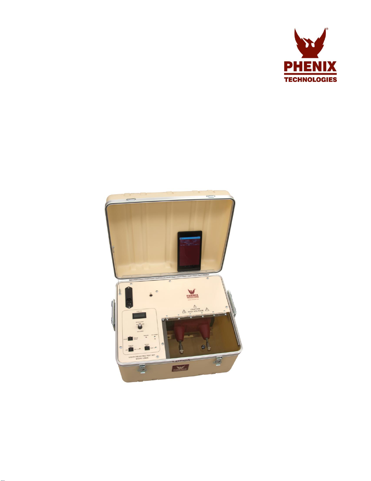
The LD60A may be ordered with an optional android tablet that is pre-loaded with the android
app. The app communicates with the LD60A via a Bluetooth link.
To use the app, the LD60A must be put in Remote Mode. With the LD60A powered on, push the
Remote Mode switch to ON. Launch the LD60A app, then press “Connect.” The Bluetooth link
will automatically shut down after 5 minutes of inactivity. When this happens, simply turn the
Remote Mode OFF then back ON again.
The app has two modes: “Automatic Test” and “Manual Controls.” Use “Automatic Test” to
perform a complete automatic test per the desired test standard. Use “Manual Controls” to
perform a single simple test.
To perform an Automatic test, first select the desired test standard to follow. Then optionally, you
may enter these values: Test ID, Oil Test Temp, Oil Sample Temp, and Oil Type. These values
represent the measured temperature of the oil. You may also change the gap and indicate
whether you used a stirrer. Press “Start Test” to initiate a test. The results will be collected and
displayed. When the test is complete, press “Test Report” to see the results. This report may
then be sent to a printer or shared via email.
Pairing with the LD60A
If for some reason you need to re-establish the paring with the LD60A, follow the instructions in
this section. Pairing creates a bond between a Bluetooth device and a host device. A host
device is an Android device (tablet, phone, or mini-PC).
The LD60A must be paired with the host device before it can establish a wireless connection and
transmit acquired data to the device. The LD60A only has to be paired once with a particular host
device.
To pair the LD60A:
1. Make sure the host device is configured to host a Bluetooth device. Refer to host device
documentation to learn how to enable Bluetooth and how to search for and pair with Bluetooth
devices.
2. Press and hold the Remote Mode On button AND the Device Pair button for at least five
seconds to put the device into pairing mode. When the BT Power and Pair LEDs blink
alternately, the device is in pairing mode and is ready to pair with the host device.
3. Select the Bluetooth device setup in the host device OS software, and then select the BTH-
1208LS-OEM when it displays. Refer to the Bluetooth documentation of your host device to
learn how to pair it with a Bluetooth device.
4. If host device requests a passkey, PIN or pairing code, enter the default value for the device
(0000).
5. Press and hold the BT Power button for two seconds to remove the device from pairing mode.

LD60A
4-4
OPERATING INSTRUCTIONS
LEDs
The BT Power LED indicates the power status of the device. The Pair LED indicates the
communication status of the device.
BT Power LED
Indication
Steady green
The device is powered and ready
Blinks continuously
Connected to host
The BT Power LED blinks alternately with the Pair LED: the device is
in pairing mode
Off
Device is off
Pair LED
Indication
Steady green
Bluetooth connection established
Blinks continuously
Communication with host over a Bluetooth connection
The Pair LED blinks alternately with the BT Power LED: the device is
in pairing mode

LD60A
4-5
OPERATING INSTRUCTIONS
Operation with TC/DE Test Cell (ASTM D877 Standard)
1. Adjust the test cell electrode by use of the measuring rod located on the test cell in the
following manner.
a. Remove the measuring rod by unscrewing it from its threaded holder.
b. Release the setscrew, which holds the adjustable electrode in place on the test
cell.
c. Place the measuring rod between the electrodes.
d. Move the adjustable electrode in until snugly against the measuring rod.
e. Moderately tighten setscrew to secure this position.
f. Remove the measuring rod and place it in the holder for safekeeping. (Distance
between the electrodes should be 0.100 of an inch if measuring rod is not used.)
2. Fill the test cell with test sample of oil according to standards procedure.
3. Place the test cell in the test chamber of the unit and close chamber lid.
4. Turn on AC power switch.
5. Select 3000 volts per second rate of rise.
6. Move the start switch to start position when stand time requirements have been met.
7. High voltage will come on; the unit will automatically raise the voltage to the desired rate
per second until failure occurs.
8. If a failure occurs, the voltage will shut off, the failure light will illuminate, and the break-
down voltage will be indicated on the kilovolt meter.
9. To return to zero, switch the stop-reset switch to stop/reset.
10. Continue test as per ASTM D877.
11. Remove the test sample of oil and repeat the above procedure for other samples.
NOTICE: The voltmeter may continue to rise slightly after the failure indicator is tripped.
This meter response delay should be ignored. The final voltage reading is the
breakdown point.

LD60A
4-6
OPERATING INSTRUCTIONS
Operation with TC/VDE Test Cell (ASTM D1816)
1. Adjust the test cell electrode gap using the double end gauge rod in the following manner.
a. Remove the gauge rod and hex key from the storage block on the side of the
cell.
b. Loosen the setscrew that holds the moveable electrode in place.
c. Place the desired end of the gauge, either .080 or .040 diameter, between the
electrodes.
d. Hold the movable electrode snugly against the gauge rod while moderately
tightening the setscrew.
e. Remove the gauge rod and replace it and the hex key back into storage.
2. Fill the test cell with test sample of oil according to standards procedure.
3. Place the test cell in the test chamber of the unit.
4. Plug cord of stirrer into chamber receptacle.
5. Close chamber cover.
6. Turn on AC power switch.
7. Set the rate of rise to 500 volts per second.
8. Move the start switch to start position when stand time requirements have been met.
9. High voltage will come on; the unit will automatically raise the voltage at the desired rate
per second until failure occurs.
10. If a failure occurs, the voltage will shut off, the failure light will illuminate, and the break-
down voltage will be indicated on the kilovolt meter.
11. To return to zero, switch the stop-reset switch down as labeled.
12. Continue test as per ASTM D1816.
13. Remove the test sample of oil and repeat the above procedure for other samples.

LD60A
4-7
OPERATING INSTRUCTIONS
Operation with optional Liquid Dielectric Comparison Unit (LDCU)
1. Make sure power to LD set being checked is turned off.
2. Place the comparison cell in the test chamber of the unit. Plug LDCU ground lead into
ground jack. Close transparent cover.
3. Turn on Input Power switch.
4. Set the Rate of Rise to the slowest speed.
5. Move the Start/Stop switch to the Start position.
6. High voltage will come on; the unit will automatically raise the voltage at the selected rate
per second.
7. Allow voltage to rise on the LDCU until it reaches 60 KV.
8. Move the Start/Stop switch to the Stop position at this time.
9. Unit under test and comparison cell should agree. If a discrepancy is found, LD unit
being checked should be sent for recalibration.
10. Turn Input Power switch off and back on to shut off high voltage and reset unit.
11. Check 15 KV, 30 KV, and 45 KV settings.

LD60A
5-1
SECTION 5: CALIBRATION
Calibration of this test set is normally not necessary.
For any internal changes, modifications, or calibrations found necessary, please return to the
factory.
Calibration of LDCU
If your unit includes the optional LDCU unit, it should be sent to Phenix Technologies factory for
recalibration at periodic intervals, not to exceed 12 months.

LD60A
6-1
ELECTRICAL SCHEMATICS
Drawing Number Description
1. 9101060 LD60A LIQUID DIELECTRIC TEST SET

LD60A
7-1
SECTION 7: MAINTENANCE AND TROUBLESHOOTING
Maintenance
No maintenance is required besides the control of fuses and control lamps located on the front
panel. Ratings of these are described in the parts list.
No solution or chemical stronger than ordinary mild soap and water solution should be applied to
the cabinet area of this unit. Care must be used when cleaning the meter faces and console
panel. Abrasives may remove printing and descriptive titles and scratch meter faces. When
cleaning, always disconnect unit from power source.
CAUTION: Never attempt to clean inside the unit as the cleaning solution may cause damage to
the electronic components.
In the event it becomes necessary to replace any parts, a description can be found with the
supplied parts list.
Troubleshooting
No “power on.”
•Is the power cord plugged in?
•Is voltage available in the wall outlet?
•Check fuse F101.
•Check the control lamp for “Input power.”
The test procedure does not start.
•Is “Input power” turned on?
•Is the compartment lid closed? Check that the micro switch is clicking when closing the lid.
•Have you turned the toggle switch to start position?
•Have you reset the test set before start-up?
The voltmeter does not show any reading.
•Check test procedure start as above.
•Check fuse F2.

LD60A
8-1
SECTION 8: PARTS LIST
ITEM
P/N
DESCRIPTION
QTY
CB1
1601469
CIRCUIT BREAKER
1
CON1
-
POWER ENTRY MODULE
1
CON2
1159900
AC OUTLET
1
CORD
1077183
POWER CORD, 8'
1
DAQ1
-
WIRELESS MULTIFUNCTION DAQ DEVICE
1
F1
1603632
FUSE
1
F2A, B
1603704
FUSE
2
KNOB
1355310
KNOB
1
LED1
-
LED, RED
1
LED2
-
LED, YELLOW
1
LED3-4
-
LED, GREEN
2
METER
1506400
DIGITAL METER
1
MOT1
1560715
MOTOR
1
MOV7
1606100
MOVISTOR
1
PS1
1590103
LINEAR POWER SUPPLY
1
RIBBON CBL
1079910
RIBBON CABLE
3
RIBBON CBL
1150191
RIBBON CONNECTOR
6
SW1
1863037
ROTARY SWITCH
1
SW2
-
ROCKER SWITCH, 120V, 5A, MOM-OFF-MOM, SPDT
1
SW3-6
1866015
LIMIT SWITCH
4
SW7
-
ROCKER SWITCH, 120V, 5A, MOM-OFF-MOM, DPDT
1
SW8
-
ROCKER SWITCH, 120V, 5A, ON-MOM, SPDT
1
T3
1890105
VARIABLE TRANSFORMER
1
7010993797
PCB1402: LD60A WITH BLUETOOTH
1
38322205
GA1-2205
1

LD60A
9-1
SECTION 9: PARTS ORDERING INFORMATION
Replacement parts are available from Phenix Technologies, Inc.
Changes to Phenix Technologies' products are sometimes made to accommodate improved
components as they become available, and to give you the benefit of the latest technical
improvements developed in our Engineering Department. It is, therefore, important when
ordering parts to include the serial number of the unit as well as the part number of the
replacement part.
When your purchase order is received at our office, a representative of Phenix Technologies will
contact you to confirm the current price of the part being ordered. If a part you order has been
replaced with a new or improved part, an Applications Engineer will contact you concerning any
change in part number.
Send orders for replacement parts to:
Service Department
Phenix Technologies, Inc.
75 Speicher Drive
Accident, Maryland 21520
Ph: 1 (301) 746-8118
Fax: 1 (301) 895-5570
E-mail: info@penixtech.com

LD60A
10-1
SECTION 10: RETURNED MATERIAL
If for any reason it should become necessary to return this equipment to the factory, the Service
Department of Phenix Technologies, Inc. must be given the following information:
Name Plate Information
Model Number
Serial Number
Reason for Return
Cause of Defect
If Phenix Technologies, Inc. deems return of the part appropriate, it will then issue an
"Authorization for Return."
If return is not deemed advisable, other inspection arrangements will be made.
NOTE: Material received at this plant without the proper authorization shall be held as
"Customer's Property" with no service until the proper steps have been taken.
Your cooperation is requested in order to ensure prompt service.
Table of contents
Other Phenix Test Equipment manuals
Popular Test Equipment manuals by other brands

GW Instek
GW Instek GDS-3000 Series user manual

Hanna Instruments
Hanna Instruments HI 38077 instruction manual

Steren
Steren MUL-630 manual

Agilent Technologies
Agilent Technologies E7495A RF Manual operation

Belkin
Belkin F4F315-T user manual

National Instruments
National Instruments PXIe-5672 Getting started guide