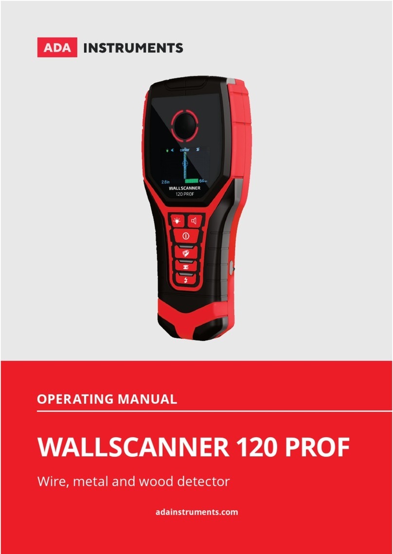
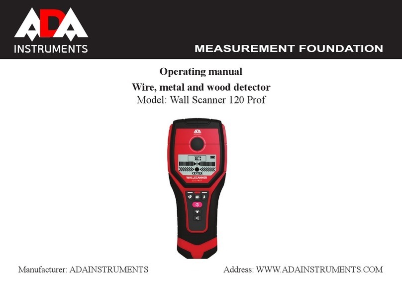
ADA INSTRUMENTS Wall Scanner 80 User manual

Operating manual
Wire, metal and wood detector
Model: Wall Scanner 80
Manufacturer: ADAINSTRUMENTS Address: WWW.ADAINSTRUMENTS.COM
INSTRUMENTS

MEASUREMENT FOUNDATION
2
INSTRUMENTSINSTRUMENTS
Table of contents
1. Intended Use . . . . . . . . . . . . . . . . . . . . . . . . . . . . . . . . . . . . . . . . . . . . . . . . . 3
2. Product Features . . . . . . . . . . . . . . . . . . . . . . . . . . . . . . . . . . . . . . . . . . . . . . . . . . . . . 3
3. Technical data . . . . . . . . . . . . . . . . . . . . . . . . . . . . . . . . . . . . . . . . . . . . . . . . . . . . . . . 5
4. Detection performance . . . . . . . . . . . . . . . . . . . . . . . . . . . . . . . . . . . . . . . . . . . . . . . . . . . . . . . . . 6
5. Operation . . . . . . . . . . . . . . . . . . . . . . . . . . . . . . . . . . . . . . . . . . . . 6
6. Operating Instructions . . . . . . . . . . . . . . . . . . . . . . . . . . . . . . . . . . . . . . . . . . . . . 8
7. Maintenance and service . . . . . . . . . . . . . . . . . . . . . . . . . . . . . . . . . . . . . . . . . . . . . . . . . 9
8. Disposal . . . . . . . . . . . . . . . . . . . . . . . . . . . . . . . . . . . . . . . . . . . . . . . 9
9. Warranty. . . . . . . . . . . . . . . . . . . . . . . . . . . . . . . . . . . . . . . . . . . . . . 10
10. Exceptions from responsibility . . . . . . . . . . . . . . . . . . . . . . . . . . . . . . . . . . . . . . . . . . . . . . . . . . . . . . . 10
Appendix 1. Certicate of acceptance and sale
Appendix 2. Warranty card

MEASUREMENT FOUNDATION
3
INSTRUMENTSINSTRUMENTS
Intended Use
The measuring tool is intended for the detec-
tion of metals (ferrous and non-ferrous metals,
e.g., rebar), joists and ‘live’ wires/conductors
in walls, ceilings and oors.
Product Features
1. Red light indicator
2. Yellow light indicator
3. Green light indicator
4. Display
5. ON/OFF button
6. Wood detection button
7. Metal/live wire detection button
8. Felt pad
9. Sensor area
10. Felt pad
11. Battery compartment

MEASUREMENT FOUNDATION
4
INSTRUMENTSINSTRUMENTS
DISPLAY ELEMENTS
a) Indicator for magnetic/non-magnetic metals
b) Indicator for the current detection mode (wood,
live wire, metal)
c) Battery indicator
d) Indicator of metal depth detection
e) Indicator of “Autocal” calibration
f) Indicator of the detected object regarding the area
center (sensor area)
g) Signal strength

MEASUREMENT FOUNDATION
5
INSTRUMENTSINSTRUMENTS
Technical data
Maximum scanning depth*:
Ferrous metals 80 mm
Non-ferrous metals (Copper) 60 mm
Copper conductors(live)** 50 mm
Wood 20 mm
Automatic switch off after approx. 5 min
Operating temperature -10 °C…+50°C
Storage temperature -20°C…+70°C
Battery 1x9 V
Operating lifetime approx. 6 h
Weight 0.12 kg
*Depends on material and size of objects as material and condition of structure.
**Scanning depth will be smaller if wires/conductors are not “live”.

MEASUREMENT FOUNDATION
6
INSTRUMENTSINSTRUMENTS
Operation
INSERTING/REPLACING THE BATTERY
Use only 9Vbattery. Insert the battery into the battery compartment (12) in accordance with the symbols in the battery com-
partment. Remove the batteries if the unit will not be used for a long period. The battery can be corroded or discharged over
long periods.
SWITCHING ON AND OFF
Protect the measuring tool against moisture and direct sun irradiation. Before switching the measuring tool on, make sure that
the sensor area 8 is dry. If required, wipe the measuring tool dry using a cloth.
The object to be measured Depth of detection Accuracy of detection
Rebar/copper tube ø 20 8 cm/6 cm
±1 cm
ø 16 7 cm/6 cm
ø 12 6 cm/5 cm
ø 6 5 cm/5 cm
Live wire and cable 5 cm
Wood Wooden beam 2 cm
Wooden batten 2 cm
Detection performance

MEASUREMENT FOUNDATION
7
INSTRUMENTSINSTRUMENTS
If the measuring tool was subject to an extreme temperature change, allow it to the adjust to the ambient temperature before
switching on. Press ON/OFF button to switch on the instrument. After a short test the detector is ready for operation. The
measuring tool automatically enter the function mode of metal detection. It is necessary to calibrate the instrument if you
hear sound alarm and see the red light indicator.
The calibration method is: place the instrument on nonmetallic surface or hold it in the hand away from any materials. Press the
metal button 7 until you hear sound alarm and green light is lit. Sound alarm and green light indicator show that the calibration
has been nished. Release button 7 to detect metal objects.
DETECTION OF OBJECTS
The detection of metal objects
Press button 7 to detect metal objects. Symbol b (the metal detection indicator) is indicated on the display and the green light is lit.
Place the measuring tool onto the surface to be scanned and move it sidewards, when the measuring tool comes close to a metal
object, the amplitude of the measuring indicator g increases. When it moves away from the object, the amplitude decreases, at the
position of maximum amplitude, the metal object is located below the center of the sensor. Indicator f is displayed on the display
and a steady tone sounds.
Indicator d (detection depth value) is displayed on the display when scanning metal objects. The accuracy of depth value is a
relation of shape and position of scanning metal objects. Symbol a shows whether metal is magnetic or not.
The detection of wooden objects
When scanning for wooden objects, the detector must come close to the wall. Then press the wood detection button 6. Don’t
move the instrument. Wait for the completion of calibration. When the calibration will be nished, you will see green light detec-
tor and there will be icon b (wood) on the display.
Place the measuring tool onto the surface and move around. When the detector come close to the wooden objects, the display
scale of g in the display will gradually increase. When the detector slowly moves away from object, the display scale will gradu-

MEASUREMENT FOUNDATION
8
INSTRUMENTSINSTRUMENTS
ally decrease. A loud tone sounds when the instrument detects the object. If the object is located in the center of sensor area, the
icon f will appear on the display. The instrument makes a steady sound and the green light is lit.
Scanning for “live” wires
Press button 7 two times to activate “live” wires mode. The icon b appears on the display. Make the calibration if there is a sound
alarm, red light indicator and the instrument can’t detect the “live” wires.
Calibration: Place the instrument on nonmetallic surface or keep it in the hand far away from any materials. Press the metal
button 7 until you hear sound alarm and green light is lit. Sound alarm and green light indicator show that the calibration has
been nished. Release button 7 to detect metal objects.
The detector can detect 50 or 60 Hz (HZ) AC live power cables, other wires can only be indicated as metal objects.
Move the measuring tool over the surface repeatedly in order to determine the specic location of the live cables. After moving
the measuring tool over the surface several times, the detector is able to pinpoint the hiding place of “live” wires/conductor.
There is a red light indicator when the measuring tool is very close to the live wire. Signal tone sound with a rapid tone se-
quence. “Live”wires/conductors can be detected easier when power consumers (e.g., lamps, appliances) are connected to the
wire/conductor being sought and switched on. Wires/conductors with 110 V, 240V and 380 V (three-phase current) are detected
with about the same scan capacity.
Operating Instructions
In accordance with the principles of tool operation, the measuring values can be impaired through certain ambient
conditions. These include, e.g. the proximity of other equipment that produce strong magnetic or electromagnetic elds,
moisture, metallic building materials. Foil-laminated insulation materials or conductive wallpaper. Therefore, please
also observe other information sources (e.g. construction plans) before drilling, sawing or routing into walls, ceilings
or oors.

MEASUREMENT FOUNDATION
9
INSTRUMENTSINSTRUMENTS
Maintenance and service
Wipe away debris or contamination with a dry, soft cloth. Do not use cleaning agents or solvents. In order not to affect the
measuring function, decals/stickers or name plates, especially metal ones, may not be attached in the sensor area 8 on the
front or back side of the measuring tool. Do not remove the felt pads 7 on the back side of the measuring tool. Replace
the felt pads when then are damaged or used. For this, completely remove the felt pads and glue the new felt pads onto
the same spots. Store and transport the measuring tool only in the protective case.
Disposal
Measuring tools, accessories and packaging should be sorted for environmental-friendly recycling.
Only for EC countries:
Do not dispose of measuring tools into household waste! According the European Guideline 2002/96/EC for Waste
Electrical and Electronic Equipment and its implementation into national right, measuring tools that are no longer usable
must be collected separately and disposed of in an environmentally correct manner.
Battery packs/batteries: Do not dispose of battery pack/ batteries into household waste, re or water. Battery packs/
batteries should be collected, recycled or disposed of in an environmental-friendly manner.
Only for EC countries:
Defective or dead out battery packs/batteries must be recycled according the guideline 91/157/EEC.

WARRANTY
This product is warranted by the manufacturer to the original purchaser to be free from defects in material and workman-
ship under normal use for a period of two (2) years from the date of purchase.
During the warranty period, and upon proof of purchase, the product will be repaired or replaced (with the same or
similar model at manufactures option), without charge for either parts of labour.
In case of a defect please contact the dealer where you originally purchased this product. The warranty will not apply to
this product if it has been misused, abused or altered. Withiut limiting the foregoing, leakage of the battery, bending or
dropping the unit are presumed to be defects resulting from misuse or abuse.
EXCEPTIONS FROM RESPONSIBILITY
The user of this product is expected to follow the instructions given in operators’ manual.
Although all instruments left our warehouse in perfect condition and adjustment the user is expected to carry out peri-
odic checks of the product’s accuracy and general performance.
The manufacturer, or its representatives, assumes no responsibility of results of a faulty or intentional usage or misuse
including any direct, indirect, consequential damage, and loss of prots.
The manufacturer, or its representatives, assumes no responsibility for consequential damage, and loss of prots by
any disaster (earthquake, storm, ood ...), re, accident, or an act of a third party and/or a usage in other than usual
conditions.
The manufacturer, or its representatives, assumes no responsibility for any damage, and loss of prots due to a change of
data, loss of data and interruption of business etc., caused by using the product or an unusable product.
The manufacturer, or its representatives, assumes no responsibility for any damage, and loss of prots caused by usage
other thsn explained in the users’ manual.
The manufacturer, or its representatives, assumes no responsibility for damage caused by wrong movement or action
due to connecting with other products.
MEASUREMENT FOUNDATION
10
INSTRUMENTS

Certicate of acceptance and sale
____________________________________________________________________________
____________________________________________________________________________
___________________________________________________________№_______________
name and model of the instrument
Corresponds to ________________________________________________________________
designation of standard and technical requirements
Data of issue __________________________________________________________________
Stamp of quality control department
Price
Sold ___________________________________ Date of sale ________________________
name of commercial establishment

WARRANTY CARD
Name and model of the product ________________________________________________
Serial number ________________date of sale_______________________
Name of commercial organization _____________________stamp of commercial organization
Warranty period for the instrument explotation is 24 months after the date of original retail purchase.
During this warranty period the owner of the product has the right for free repair of his instrument in case of manufacturing defects.
Warranty is valid only with original warranty card, fully and clear lled (stamp or mark of thr seller is obligatory).
Technical examination of instruments for fault identication which is under the warranty, is made only in the authorized service center.
In no event shall manufacturer be liable before the client for direct or consewuential damages, loss of prot or any other damage which occur in the result
of the instrument outage.
The product is received in the state of operability, without any visible damages, in full completeness. It is tested in my presence. I have no complaints to
the product quality. I am familiar with the conditions of qarranty service and I agree.
purchaser signature _______________________________
Before operating you should read service instruction!
If you have any questions about the warranty service and technical support contact seller of this product

WARRANTY DOESN’T EXTEND TO FOLLOWING CASES:
1. If the standard or serial product number will be changed, erased, removed or wil be unreadable.
2. Periodic maintenance, repair or changing parts as a result of their normal runout.
3. All adaptations and modications with the purpose of improvement and expansion of normal sphere of product application, men-
tioned in the service instruction, without tentative written agreement of the expert provider.
4. Service by anyone other than an authorized service center.
5. Damage to products or parts caused by misuse, including, without limitation, misapplication or nrgligence of the terms of service
instruction.
6. Power supply units, chargers, accessories, wearing parts.
7. Products, damaged from mishandling, faulty adjustment, maintenance with low-quality and non-standard materials, presence of any
liquids and foreign objects inside the product.
8. Acts of God and/or actions of third persons.
9. In case of unwarranted repair till the end of warranty period because of damages during the operation of the product, it’s transporta-
tion and storing, warranty doesn’t resume.


Руководство по эксплуатации
Детектор проводки, металла, дерева
Модель: Wall Scanner 80
Производитель: ADAINSTRUMENTS Адрес: WWW.ADAINSTRUMENTS.COM
INSTRUMENTS

MEASUREMENT FOUNDATION
16
INSTRUMENTSINSTRUMENTS
Оглавление
1. Применение . . . . . . . . . . . . . . . . . . . . . . . . . . . . . . . . . . . . . . . . . . . . . . . . . . . . 17
2. Свойства . . . . . . . . . . . . . . . . . . . . . . . . . . . . . . . . . . . . . . . . . . . . . . . . . . . . . 17
3. Технические данные . . . . . . . . . . . . . . . . . . . . . . . . . . . . . . . . . . . . . . . . . . . . . . . . . . . . . . . 19
4. Работа с инструментом . . . . . . . . . . . . . . . . . . . . . . . . . . . . . . . . . . . . . . . . . . . . . . . . . . . . . . . . . 20
5. Указания по применению . . . . . . . . . . . . . . . . . . . . . . . . . . . . . . . . . . . . . . . . . . . . . 23
6. Техобслуживание и сервис . . . . . . . . . . . . . . . . . . . . . . . . . . . . . . . . . . . . . . . . . . . . . . . . . . 23
7. Гарантия . . . . . . . . . . . . . . . . . . . . . . . . . . . . . . . . . . . . . . . . . . . . . . . . . . . . . . . 24
8. Освобождение от ответственности . . . . . . . . . . . . . . . . . . . . . . . . . . . . . . . . . . . . . . . . . . 24
Приложение 1. Свидетельство о приемке и продаже
Приложение 2. Гарантийный талон

MEASUREMENT FOUNDATION
17
INSTRUMENTSINSTRUMENTS
Применение
Настоящий измерительный инструмент
предназначен для поиска в стенах, потолках
и полах металлов (черных и цветных
металлов, например, арматурной стали),
деревянных балок, а также электрокабелей
под напряжением.
Свойства
1. Красный световой индикатор
2. Желтый световой индикатор
3. Зеленый световой индикатор
4. Дисплей
5. Кнопка Вкл/Выкл
6. Кнопка для обнаружения дерева
7. Кнопка для обнаружения металла/
электрокабеля под напряжением
8. Фетровая подкладка скольжения
9. Сенсорная зона
10. Фетровая подкладка скольжения
11. Батарейный отсек

MEASUREMENT FOUNDATION
18
INSTRUMENTSINSTRUMENTS
ЭЛЕМЕНТЫ ИНДИКАЦИИ
a) Индикатор магнитных и немагнитных металлов
b) Индикатор режима работы (дерево,
электропровод под напряжением, металл)
c) Индикатор заряда батареи
d) Индикатор глубины обнаружения металла
e) Индикатор настройки “Autocal”
f) Индикатор обнаружимого объекта относительно
центра области обнаружения (сенсорной зоны)
g) Уровень сигнала

MEASUREMENT FOUNDATION
19
INSTRUMENTSINSTRUMENTS
Технические данные
Глубина обнаружения, макс.*:
черные металлы 80 мм
цветные металлы (медная труба) 60 мм
медные кабели (под напряжением)** 50 мм
древесина 20 мм
Автоматическое выключение прибл. через 5 мин
Рабочая температура -10 °C…+50°C
Температура хранения -20°C…+70°C
Батарея 1x9 В
Продолжительность работы
(щелочных батарей) около 6 ч
Вес 0.12 кг
* в зависимости от материала и размера объекта, а так же материала и состояния основания
** глубина обнаружения будет меньше, если электрокабель не находится под напряжением

MEASUREMENT FOUNDATION
20
INSTRUMENTSINSTRUMENTS
Работа с инструментом
УСТАНОВКА/СМЕНА БАТАРЕИ
Используйте только батарею 9В.
Вставьте батарею в батарейный отсек (12). Соблюдайте полярность.
Если Вы продолжительное время не пользуйтесь измерительным инструментом, то батарея должна
быть вынута из инструмента. При продолжительном хранении инструмента батарея может окислиться и
разрядиться.
Измеряемый объект Глубина обнаружения Точность обнаружения
Арматурный стержень/
медная трубка
ø 20 8см/6см
±1 см
ø 16 7см/6см
ø 12 6см/5см
ø 6 5см/5см
Электрокабель под напряжением и кабель 5 см
Древесина Деревянная балка 2 см
Деревянная рейка 2 см
Параметры обнаружения
Table of contents
Languages:
Other ADA INSTRUMENTS Security Sensor manuals
Popular Security Sensor manuals by other brands
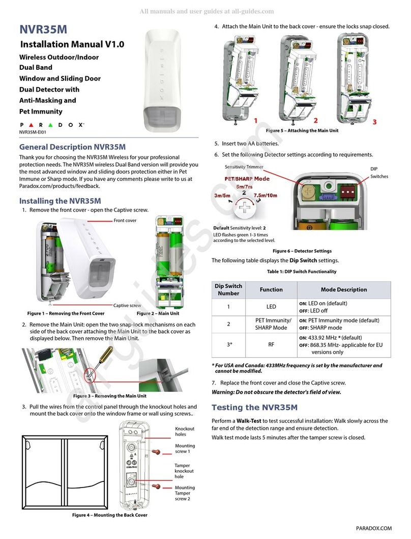
Paradox
Paradox NVR35M installation manual
HIK VISION
HIK VISION DS-PD2-T10AME-EH quick start guide
HANYOUNG NUX
HANYOUNG NUX PEA Series instruction manual
Cooper & Hunter
Cooper & Hunter SPHNS-S01E Installation & maintenance manual
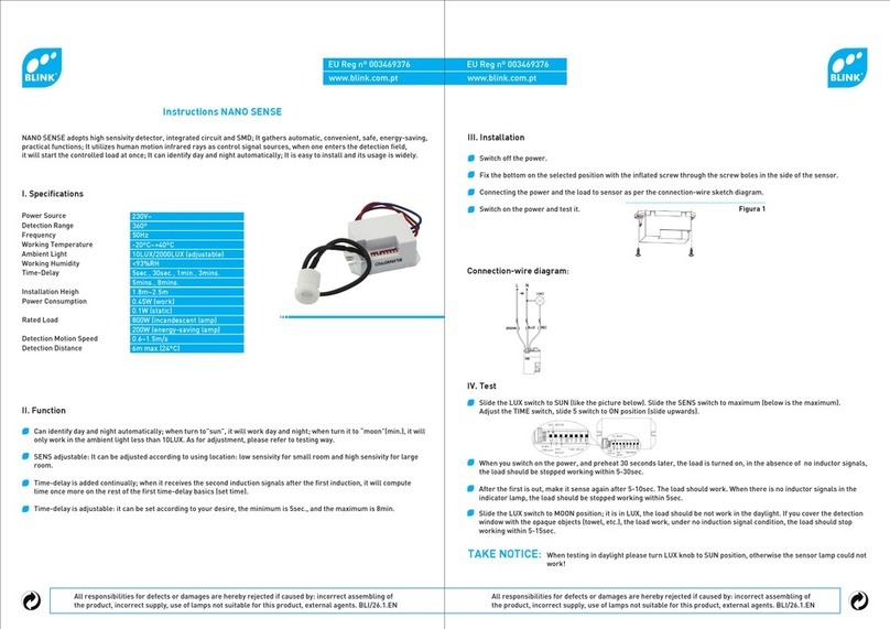
B-Link
B-Link NANO SENSE instructions

Healthcraft
Healthcraft Tub-Rail TBR-S instruction manual
C.P. Electronics
C.P. Electronics EBDHS-DNET1 installation guide
Paradox
Paradox ENVY NVX80 Reference and installation manual

Paradox
Paradox ESPRIT728 Programming guide
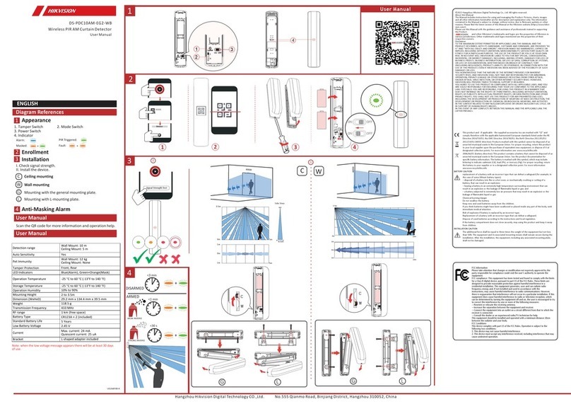
HIK VISION
HIK VISION Baseline DS-PDC10AM-EG2-WB user manual
STAR TEC
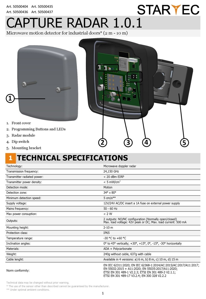
STAR TEC CAPTURE RADAR 1.0.1 manual

PerkinElmer
PerkinElmer 200 UV/VIS Series user manual
