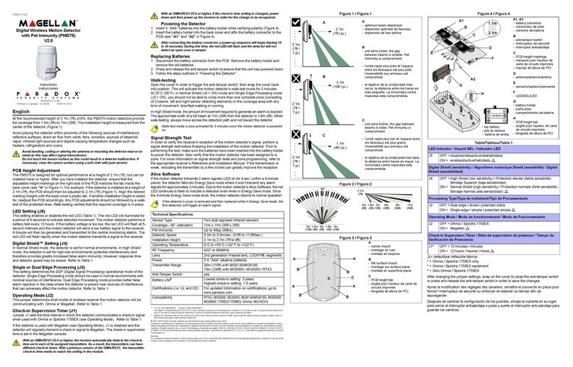
INSTALLATION
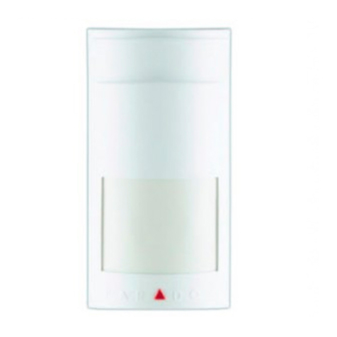
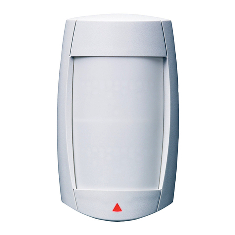
Select the detector’s installation site,
based on required coverage and
recommended height of 2.1m (7ft).
Avoid proximity to any of the following:
reflective surfaces, direct air flow from
vents, fans and windows, sources of
steam/oil vapor, objects causing
temperature changes such as heaters,
refrigerators and ovens, infrared light
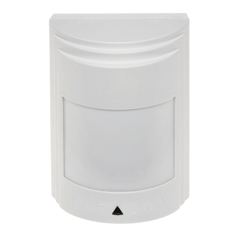
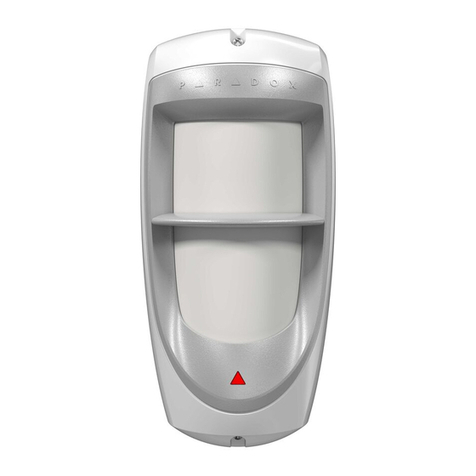
sources. The detector comes equipped
with Paradox “no dead zone” WA-1
standard lens. For more information on
the full range of Paradox lenses, visit
our web site at http:\www.paradox.ca
and click on our product catalogue. If
another lens pattern is required, choose
the desired lens (refer to Figure 1 on
other side) and:
a) remove front cover of the detector
(1) by gently pushing the cover pin
(2) in with a screwdriver.
b) pull out the bezel (4) by lightly pressing on bezel pins (5) and (6).
c) remove the lens (3) and replace it with the alternate lens. (Note: the
grooves
should be inside the bezel and the lens catalogue number on top.)
d) replace the bezel by lightly pressing it into place. Make sure that the lens is
centered.
Do not touch the sensor surface as this could result in detector
malfunction. Clean with soft cloth and pure alcohol if necessary.
After selecting the detector's location, drill or punch out holes for the screws as
described in Figure 2 (refer to other side).
CORNER MOUNT: Carefully remove the PCB (9) by loosening the PCB screw (8)
and use holes A, B, C and D.
FLAT SURFACE MOUNT: Carefully remove the PCB (9) by loosening the PCB
screw (8) and use holes E, F, G and H.
WIRING: Run the four wires through entry holes I and J and connect them to their
respective terminals on a Digiplex DGP-48 or DigiplexNE DGP-NE96 control panel.
If another installation height is called for, move the PCB to the proper installation
height indicated on the left side of the PCB. A small adjustment may be required
depending on the protected area. Any PCB adjustments should be followed by a
walk-test of the protected area. Walk-testing verifies that the required coverage is
met as per the lens pattern.
COVERAGEADJUSTMENT
Using a Paradox® standard lens at the recommended installation height of 2.1m
(7ft) to 2.7m (9ft) ±10%, the addressable digital PIRs will provide full coverage from
1.2m (4ft) to 12m (40ft), without any dead zones. Ensure that the PCB is fixed at
the 2.1m (7ft) mark. A small vertical adjustment of the PCB of ±0.5mm (0.02in) may
be required.
POWERTHEMOTION DETECTOR
Connect the four terminals labeled red, black, green and yellow of each detector to
the corresponding terminals on the control panel as shown in Figure 1. Powering
the detector initiates a self-testing program for the signal processor and memory.
The red and green LEDs will flash to indicate that the system is fully operational.
When the LEDs are no longer flashing, the detector is ready.
MODULEPROGRAMMING
To enter the Module Programming Mode:
1) Press and hold the [0] key
2) Key in the [INSTALLERCODE]
3) Key in section [953] (DGP-48) / [4003] (DGP-NE96)
4) Key in the detector’s 8-digit [SERIALNUMBER]
5) Key in the 3-digit [SECTION]you wish to program
6) Turn the desired option on/off or key in the required data
Please note that the serial number is located on the detector’s metal shield (refer to
Figure 1 on other side).
SINGLE/DUALEDGEPROCESSING
This feature determines the DSP (digital signal processing) operational settings for
the detector.
Section [001]:Option [1] = ON (default)
In “Single edge” processing mode, the Digital Auto Pulse Signal Processing†
feature, adds the entry and exit signals until the value representing an alarm
situation is reached.
Section [001]:Option [1] = OFF
In “Dual edge” processing mode, entry signals are processed separately from exit
signals. Both have to reach required energy levels before an alarm is generated.
Therefore, if the entry signals have reached the required energy levels, but the exit
signals have not, an alarm signal will not be generated. This setting provides better
false alarm rejection in the case where the detector is placed near sources of
interference that can adversely affect the motion detector.
ALARMINDICATION
Section [001]: Option [2]
When option [2] in section [001] is enabled and the detector detects a signal that
matches the characteristics of a movement signal and reaches the required
accumulated energy level for an alarm, the red LED will turn on for 5 seconds.
MOVEMENTANDNON-MOVEMENTSIGNALINDICATION
Section [001]: Options [3] and [4]
Movement Signal Indication: When option [3] in section [001] is enabled and the
detector detects a signal that matches the characteristics of a movement signal,
but does not reach the required energy levels for an alarm, the red LED will flash
once indicating the signal was kept in memory.
Non-Movement Signal Indication: When option [4] in section [001] is enabled and
the detector detects a non-movement signal, the green LED will flash once
indicating the signal was rejected.
TAMPERRECOGNITION
Section [001]: Option [5]
When option [5] in section [001] is enabled and the tamper switch is open (cover
removed), the detector will send a tamper message to the control panel.
DIGITALSHIELDSETTING
The setting of the Digital SHIELD™ determines several Digital Processing
parameters:
1) Accumulated energy level required to generate an alarm
2) EMI/RFI digital filter level
3) Digital amplifier gain.
Section [002]: Sensitivity
Normal Shield should be chosen for normal environments while High Shield should
be selected for areas at high risk of false alarms. In High Shield mode, all three
parameters mentioned above are automatically set for high-risk environments. The
detector will therefore provide greatly increased false alarm immunity. However,
response time and detector speed might be somewhat slower. Using lower shield
settings sets the above parameters for lower risk environments.
Due to the shield algorithm and the relatively heavy mathematical
calculation, an alarm condition can be generated 0.25 sec. to 2 sec. after the
actual movement, depending on the type of signal being processed.
WALK-TESTING
When walk-testing, always move across the detection path, not toward the
detector. At 68°F (20°C) you should not be able to cross more than one complete
zone (consisting of 2 beams, left and right sensor detecting elements) in the
coverage area with any kind of movement. When using higher level digital shield
settings, the amount of movement required to generate an alarm is increased. The
approximate width of a full beam at 12m (40ft) from the detector is 1.8m (6ft). The
installer should test the detectors at least once per year.
000 = Very Low Shield 002 = Normal Shield (default)
001 = Low Shield 003 = High Shield
