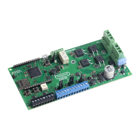
Adaptive 1109502601SP User manual

© Copyright 2008 Adaptive Micro Systems LLC. All rights reserved.
Adaptive Micro Systems • 7840 North 86th Street • Milwaukee, WI 53224 USA • 414-357-2020 • 414-357-2029 (fax) • http://www.adaptivedisplays.com
Adaptive is a registered trademark of Adaptive Micro Systems. MEDIAMaster is a trademark of Adaptive Micro Systems.
All other brand and product names are trademarks or registered trademarks of their respective companies.
MAY 21, 2008 PN 1109610108 REV. A
Replacing the Billboard PC Controller
(PN 1109502601SP)
The PC controller transmits and converts signals between control cabinet components and
the billboard. The PC controller’s removable 40GB hard drive stores operating programs
such as Windows XP and a web–based content management software.
Figure 1. Front view of PC controller.
Before you begin
Kit contents
Tools / Safety equipment needed
Full body safety harness with lanyard
#2 Phillips head screw driver
Part Number Qty Description
1109210101 1PC controller relays messages to and from the billboard.
1181220001 1 40GB removable hard drive stores billboard operating software and program files.
Note: Software programs are pre–installed at the factory.
Key 1Hard drive key is used to lock the hard drive into place in the PC controller or
unlock the hard drive for removal.
Note: The PC controller will not function if the hard drive is not locked into place.
Power cord 1 The power cord connects to the UPS and supplies power to the PC controller.
Mounting rails 2Side mounting rail assemblies, used for rack mounting the PC controller.
1109610108 1 Instructions

REPLACING THE BILLBOARD PC CONTROLLER
2PN 1109610108 REV. A
Replacing the PC controller
➩To replace the PC controller
1. Open both doors on the control cabinet.
• If applicable, remove the control cabinet’s padlock.
• Turn cabinet handle and pull open the control cabinet door.
2. Access the defective PC controller’s desktop.
A. If applicable, unlock the KVM drawer and flip open the monitor.
B. Press the KVM on / off button.
C. Press the appropriate KVM selection button to access the PC desktop.
Figure 2. KVM drawer key components.
3. Power off the PC controller to be replaced.
• Close all operating programs.
• Shut down Windows (A – D).
Figure 3. Controlled shut down of Windows.
WARNING! Possible fall hazard. When servicing billboard components, service personnel must use
a full body safety harness with lanyard. Connect the lanyard to the billboard head’s safety cables;
otherwise serious injury or death may occur.
#7 Selection button
(PC #1)
ON/OFF button
Drawer lock
Drawer handle
Flip
monitor
open
C
A
B
#8 Selection button
(PC #2)
A
B
C
D

REPLACING THE BILLBOARD PC CONTROLLER
MAY 21, 2008 3
4. Disconnect the PC controller’s power and communication cables.
• Unplug the PC controller’s power cord from the UPS.
• Remove all other cables plugged into the back of the PC controller.
5. Remove the PC controller from the control cabinet.
A. Slide the PC controller out, exposing the metal levers on the PC side rails.
B. Press both metal levers down and remove the PC controller.
Note: Do NOT remove side mounting rail assemblies from the control cabinet.
Figure 4. Removing the PC controller.
6. Install the replacement PC controller.
• Guide the PC side rails into the open slots on the existing side mounting rail
assemblies.
• Slide the PC controller fully into the cabinet. The metal levers will click into place.
Figure 5. Installing the PC controller.
A
B
PC side rail
Metal
lever Side mounting
rail assembly
Side mounting rail assembly
PC side rail

REPLACING THE BILLBOARD PC CONTROLLER
4PN 1109610108 REV. A
7. Connect all cables associated with the PC controller.
Figure 6. PC controller cable connections.
8. Turn on the PC controller.
PC controller rear view
BCD
FE
A
UPS receptacles
Item Port Component connection
APower PC #1 power cord label ID #17 plugs into UPS load 1’s top receptacle.
PC #2 power cord label ID #22 plugs into UPS load 2’s top receptacle.
BMouse
Keyboard
VGA
PC #1 connects with 3–in–1 KVM cable label ID #13.
PC #2 connects with 3–in–1 KVM cable label ID #26.
CEthernet PC #1 connects with Ethernet cable label ID #5.
PC #2 connects with Ethernet cable label ID #30.
DUSB-3
PC #1 connects with USB cable label ID #14.
PC #2 connects with USB cable label ID #25.
EUSB-4 The USB cable (label ID #28) connection provides a communication pathway
between PC #1 and the UPS. Only applicable with PC #1.
FDVI
PC #1 connects with DVI cable label ID #20.
PC #2 connects with DVI cable label ID #24.

REPLACING THE BILLBOARD PC CONTROLLER
MAY 21, 2008 5
Updating the player.ini file
To communicate with the billboard, the IP address in the player.ini file on the PC controller
must match the billboard’s IP address.
➩To update the player.ini file
1. Using the KVM drawer, access the replacement PC controller’s desktop, see Figure 2
on page 2 for more details.
2. Open the Shortcut to User folder on the desktop.
Figure 7. Shortcut to User folder.
3. Double click the player.ini file. The following information will appear on the monitor:
Figure 8. Player.ini file settings.
4. Click Save.
Verifying PC controller operation
The PC controller is operating properly if the following can be performed from a remote
Internet connection.
Change or update the image content on the billboard.
Access the UPS web console (only applicable if PC controller #1 was replaced).
Verify Windows assigned the correct COM port to the USB to RS485 adapter. Billboard
image content is not affected if this is not correct. See “Verifying USB to RS485 COM
port” on page 6 for details.
[Settings]
model=AlphaEclipse MEDIAMaster
drawlostframes=0
rows=144
columns=448
dotpitch=20
palette=RGB
colordepth=24
driverx=16
drivery=16
serialnumber=
hwport=COM4:
ftpport=40003
pasvaddress=10.11.11.254
pasvport=40100
pasvrange=50
lightsensors=2
tempsensors=1
Change the IP address to match the
billboard’s IP address.
PC controller #2 (pasvport=40200)
Note: The player.ini file settings contain specific
billboard information and will vary for every billboard.

REPLACING THE BILLBOARD PC CONTROLLER
6PN 1109610108 REV. A
Verifying USB to RS485 COM port
Billboard light sensors, temperature readings, and other RS485 signals critical to the
operation of the billboard will not be received by the PC controller, and eventually affecting
billboard operation.
1. Click Start, Settings, and Control Panel.
Figure 9. Accessing the PC controller’s control panel.
2. Scroll down and select System.
Figure 10. Control panel window.
Click Start.
Click Control Panel.
Click Settings.C
B
A
Double click
System.

REPLACING THE BILLBOARD PC CONTROLLER
MAY 21, 2008 7
3. Click the Hardware tab and select Device Manager.
Figure 11. System properties window.
4. If applicable, move the Device Manager window into view otherwise proceed to
Step 5.
Figure 12. Moving the device manager window.
5. Ensure the USB Serial Port (COM4) is shown, if (COM4) is not shown double click
USB Serial Port.
Figure 13. Device manager window.
Click the Hardware tab.
Click the Device Manager.
The Device Manager window
may open out of the viewing
area on the KVM monitor.
A
B
Right click
Device
Manager
tab on the
Taskbar.
Click Move.Arrow cursor
automatically moves over the
Device Manager window.
Click and hold the left mouse
button and drag the window into
view on the KVM monitor.
A
B
C
Alternate method: Simultaneously press Alt + Spacebar, release and press M. Press and hold the Left arrow key
until the Device Manager window comes into view. Click the left mouse button to release window.
If (COM4) is not shown, double click.

REPLACING THE BILLBOARD PC CONTROLLER
8PN 1109610108 REV. A
6. Click the Port Settings tab and select Advanced.
Figure 14. USB serial port properties window.
7. Open the COM Port Number’s drop down menu and select COM4, even if it is in use.
Click OK
Figure 15. Changing the COM port.
8. Click Yes to the Communications Port Properties prompt.
Figure 16. Communications port properties prompt.
9. Click OK or close all windows opened during this procedure. Repeat steps 1 – 5 and
verify the correct COM port has been assigned and saved.
Click Advanced.
Click Port Settings tab.
A
B
Select COM4, even if it is in use.
Click OK.
A
B
Click Yes.
Other Adaptive Controllers manuals
Popular Controllers manuals by other brands

Asparion
Asparion D400 Guide

SEA
SEA CORONA S Series Installation Manual and Security Information
Allen-Bradley
Allen-Bradley SLC 500 1747-L20 installation instructions
Invertek
Invertek Optidrive Elevator Quick start up guide
Kemper
Kemper KTS DN 32 Mounting and operating instructions
Sven
Sven AVR-500 LCD Operation manual
Tiger Controls
Tiger Controls TROOM-7 instructions
Airzone
Airzone AZX6GTCFUJ manual
Nexxt Solutions
Nexxt Solutions NHA-B100 manual
Pride Mobility
Pride Mobility Controller Flight Basic operation instructions
Weber
Weber Markoprint XB4JET MANUAL FOR INSTALLATION, OPERATION AND MAINTENANCE
Parker
Parker PAC installation guide
