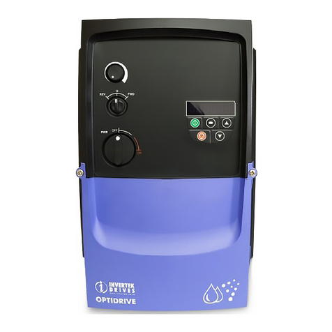
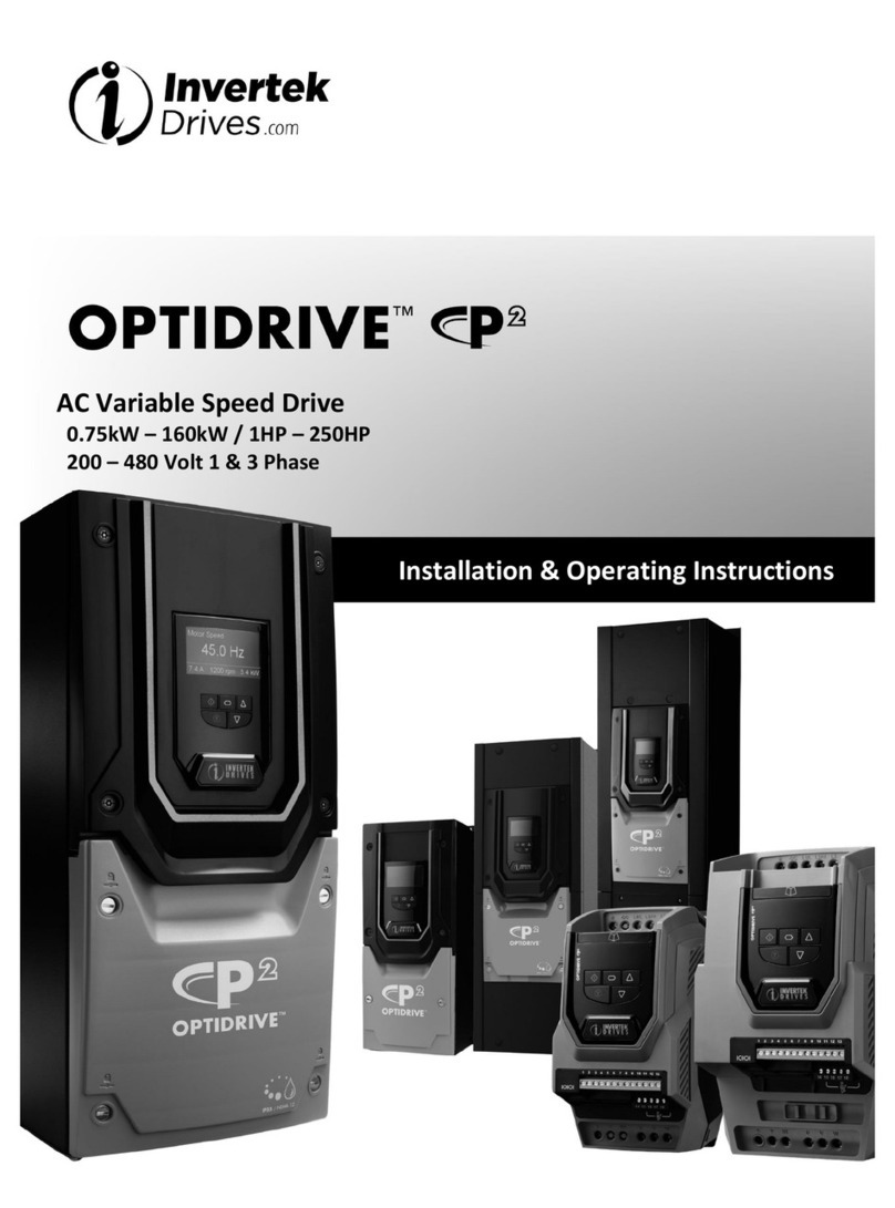
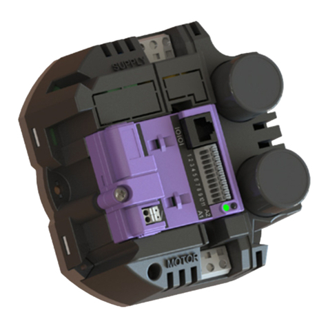
Invertek Optidrive Elevator Troubleshooting guide

Quick Start-up Guide
for geared/induction motor applications
Step 1 Electrical connections
Step 2 Motor nameplate data entry
Step 3 Encoder nameplate data entry (if an encoder is used)
Step 4 Motor auto-tune
Control terminal connections (default)
Speed profile setup
Digital input configuration parameter (P1-13)
Optimising & improving travel comfort
Useful parameters
Fault messages
Slide out help card
Quick reference to
travel curve setup
Back-lit elevator logo
Logo flashes if the drive
trips
RJ45 port
Modbus/CanOpen
connection
Expansion slot
Encoder Interface
Pluggable control
terminals
OPTIDRIVE elevator | Quick Start-up Guide | Version 1.0
Please refer to the ‘Optidrive P2 Elevator User Guide’ for
complete safety and operating instructions, this can be found
at www.invertekdrives.com or by scanning this QR code

Step 1 Electrical connections
Action Additional Information
Connect
Motor
Check phases =
U>U, V>V, W>W
Connect
Braking
Resistor
Connect resistor
to ‘+’ and ‘BR’
terminals
kW HP
Min resistance
200-240VAC
1 Phase Input
Min resistance
200-240VAC
3 Phase Input
Min resistance
380-480VAC
3 Phase Input
Suggested
resistor power
rating (W)
0.75 1 50 1000
1.5 2 32 1000
2.2 3 25 1000
4 5 20 50 1000
5.5 7.5 20 40 1500
7.5 10 22 40 2000
11 15 22 40 3000
15 20 12 22 4000
18.5 25 12 22 4500
22 30 6 22 5000
30 40 6 12 7000
37 50 6 12 8000
If an
encoder is
used connect
the encoder
to the drive
using the
Encoder
interface
Module
Check that the
correct Encoder
interface module
type is installed.
Check encoder
wiring is correct.
Encoder interface module types :
OPT-2-ENCOD-IN = 5V TTL Encoder.
OPT-2-ENCHT-IN = 24V HTL Encoder.
• Encoder connections:
Terminal ENCOD-IN ENCHT-IN
1 A A
2 A/ A/
3 B B
4 B/ B/
5 +5V *No Connection
6 0V *No Connection
*Provide 24V to the Encoder from an external power source,
or use T1 (24V) and T7 (0V) of drive control terminals.
Apply rated voltage
to the drive.
L1>L1, L2>L2,
L3>L3
Check that the
drive displays
or .
See ‘Fault Messages’ section if a fault message is shown.
OPTIDRIVE elevator | Quick Start-up Guide | Version 1.0
Step 2 Motor nameplate data entry
Action Additional Information
Open advanced
parameter access
Set P1-14 to 201
Enable Geared
(IM) motor control
Set P4-01 to 0 Advanced Vector Control
Enter motor rated
voltage
Enter value into P1-07 Enter Voltage value as shown on the motor
nameplate (Volts).
Enter Motor Rated
Current
Enter value into P1-08 Enter Current value as shown on the motor
nameplate (Amps).
Enter Motor Rated
Frequency
Enter value into P1-09 Enter Frequency value as shown on the
motor nameplate (Hz).
Enter Motor Rated
Speed
Enter value into P1-10 Obtained from Motor nameplate.
The drive will now operate in Rpm.
Enter Motor
power factor
Cos Ø
Enter value into P4-05* Obtained from Motor nameplate
*If Motor power factor is unknown use Vector
IM speed control instead (P4-01 to a 1).
Step 3 Encoder nameplate data entry (if an encoder is used)
Action Additional Information
Enable Encoder Set P6-05 to 1 Enables Encoder Feedback
Enter Encoder
Type
Enter Encoder Pulses per
revolution value into P6-06
Enter value as shown on encoder nameplate/
datasheet e.g. 1024
Step 4 Motor auto-tune
A Motor Auto-tune must be carried out in order to measure the motor electrical characteristics,
brakes will be applied by the drive (unless controlled by other means) during this test.
Action Additional Information
If motor contactor(s) are controlled by the elevator controller check that they are closed.
Close Safe
Torque off input
connections
1 2 3 4 5 6 7 8 9 10 11 12 13
Safety relay
Drive should now show if not see
‘Fault messages’ section of this guide.
Enable Motor
Auto-tune
Set P4-02 to a 1 and press
the button.
The display will show . Once the
Auto-tune is completed P4-02 will return to 0
and the display will show (P7-01 thru to
P7-06 will be populated).
Note: Motor Auto-tune will need to be repeated
if the motor, motor cables, motor parameters or
drive control mode is changed in P4-01.

Control terminal connections (default) Digital input configuration parameter (P1-13)
The below table assumes the drive already has a direction command given i.e. Terminal 2 or 3 input
is high
P1-13 Digital
Input 3 (T4)
Analog
Input 1 (T6)
Analog
Input 2 (T10) Active Speed
1
(Option 1)
Default
100 P2-02 (HighSpeed)
0 or 1 0 1 P2-03 (Intermediate Speed)
0 or 1 1 0 or 1 P2-04 (Inspection Speed)
000P2-01 (Levelling Speed)
2
(Option 2)
1 0 *1 P2-02 (High Speed)
0 or 1 1 *1 P2-04 (Inspection Speed)
0 0 *1 P2-01 (Levelling Speed)
3
(Option 3)
100 P2-02 (High Speed)
0 or 1 1 0 P2-04 (Inspection Speed)
000P2-01 (Levelling Speed)
4
(Option 4)
1 0 **1 P2-02 (High Speed)
0 or 1 1 **1 P2-04 (Inspection Speed)
0 0 **1 P2-01 (Levelling Speed)
5 (Option 5) Brake release monitoring function see ‘Optidrive P2 Elevator User Guide’
6
(Option 6)
(Multispeed
Selection)
000 P2-01
100 P2-02
010 P2-03
110 P2-04
001 P2-05 (Max 5.0Hz)
101 P2-06
011 P2-07
111 P2-08
1= Input High 0 = Input Low
* If 0 the drive will trip on External trip or F-Ptc if a motor thermistor fitted and Ptc-th has been
selected in P2-33.
** If 0 drive will fast stop using deceleration ramp in time set in P2-25., if P2-25 is zero the drive will
coast to stop.
Speed profile setup
Related Parameters Action
P1-03 (Accel ramp time)
P1-04 (Decel ramp time)
P2-01 (Levelling Speed)
P2-02 (Run Speed)
P2-03 (Intermediate
Speed)
P2-04 (Inspection Speed)
P3-01 (Accel start Jerk)
P3-02 (Accel end Jerk)
P3-03 (decel start Jerk)
P3-04 (decel end Jerk)
P3-05 (Stopping Jerk)
+24Vdc 100mA Output
+10Vdc 10mA Output
Open = Terminal 4 Selection
Closed = Inspection Speed
0V
Drive Healthy (24Vdc Output)
0V
Open = Terminal 4 Selected Speed
Closed = Intermediate speed
Drive Running (24Vdc Output)
ST0 +
ST0 -
RL1-C
RL1-NO
RL1-NC
RL2-A
RL2-B
1
2
3
4
5
6
7
8
9
10
11
12
13
14
15
16
17
18
+24Vdc
0Vdc
Optional
External
Power
Supply
Open = Levelling Speed
Closed = High Speed
Motor Contactor
Control
Common
Motor Brake
Control
Common
Open = StoP
Closed = Run Up (Forward)
Open = StoP
Closed = Run Down (Reverse)
OPTIDRIVE elevator | Quick Start-up Guide | Version 1.0

OPTIDRIVE elevator | Quick Start-up Guide | Version 1.0
Optimising & improving travel comfort
Symptom Possible
Cause
Control
Modes Possible Corrective Actions Notes
1 –
Rollback
During
starting
Brake
release time
maybe too
short.
P4-01 =
0-3
Increase P3-07 (Brake Release time) P2-02 (HighSpeed)
P4-01 =
0,1,2
Increase P4-03 (Speed Controller
P-Gain)/ decrease P4-04 (Speed
Controller I-Gain)
Higher value=faster
response/ Eliminates
steady state speed
error.
P4-01 =
0,1,2
If Modifying PP4-03/P4-04 is not
successful use Closed loop (With
Encoder)
P4-01 = 2 If Modifying P4-03/P4-04 is not
successful Increase value in parameter
P1-11 (V/F Mode Voltage Boost).
Take care when
modifying Increasing
too high could
overheat the motor
1 –
Jerk Felt
During
starting
Brake not
releasing
quick
enough
P4-01 =
0,1,2
Reduce P3-07 (Brake Release time)
Acceleration
time too
short
P4-01 =
0,1,2
Increase P3-01 (Acceleration S-Ramp
1 duration)
2 –
Vibration
during
speed
transition
Speed Loop
gains need
adjusting
P4-01 =
0,1
Reduce P4-03 (Speed Controller
Proportional gain) & Adjust
P4-04 (Speed Controller Integral
gain) to reduce steady state speed
error.
If proportional gain is
set to low the system
response will be
slow, if too high the
system could become
unstable and show
as Vibration.
3 –
Jerk Felt
During
stopping
Brake
coming on
too early
P4-01 =
0,1,2
Decrease P3-09 (brake apply speed).
or
Use motor Brake control option 2, see
10.6.2
Deceleration
time too
short
P4-01 =
0,1,2
Increase P3-01 (Acceleration S-Ramp
1 duration)
3 –
Floor
Levelling-
Short
Drive is
reaching
current
limit and
extending
ramp time
P4-01 =
0,1,2
Check drive current rating matches
system requirements.
Increase P4-07(Motoring Torque
Limit)/
P4-09 (Regen current limit)
Check that
increasing P4-07/
P4-09 is in line with
the capability for the
connected motor.
Speed Loop
gains need
adjusting
P4-01 =
0,1
Increase P4-03 (Speed Controller
Proportional gain) to achieve faster
response & Adjust P4-04 (Speed
Controller Integral gain) to reduce
steady state speed error.
If proportional gain is
set to low the system
response will be
slow, if too high the
system could become
unstable and show
as Vibration.
Motor data
incorrect
causing
error
between
commanded
and actual
speed
P4-01 =
0,1
Open
Loop
• Check that the motor nameplate
data (P1-09, P1-10) are correct
and that an autotune has been
successful.
• Adjust Motor rated speed
(P1-10) to increase/decrease slip
amount.
Levelling
time too
short
P4-01 =
0,1,2
Increase P3-05 (Levelling S-ramp
duration)
Notes

OPTIDRIVE elevator | Quick Start-up Guide | Version 1.0
Fault messages
Fault Code Description Corrective Action
Brake resistor
overload
The drive software has determined that the brake resistor is
overloaded (based on the values entered in P3-13 and P3-14),
and trips to protect the resistor. Always ensure the brake resistor is
being operated within its designed parameter before making any
parameter or system changes.
To reduce the load on the resistor, increase deceleration the time,
reduce the load inertia or add further brake resistors in parallel,
observing the minimum resistance value for the drive in use.
Instantaneous over
current on drive
output. Excess load
on the motor.
Fault Occurs on Drive Enable
Check the motor and motor connection cable for phase – phase
and phase – earth short circuits.
Check the load mechanically for a jam, blockage or stalled
condition
Ensure the motor nameplate parameters are correctly entered,
P1-07, P1-08, P1-09.
If operating in Vector mode (P4-01 – 0 or 1), also check the
motor power factor in P4-05 and ensure an autotune has been
successfully completed for the connected motor.
Reduced the Boost voltage setting in P1-11
Increase the ramp up time in P1-03
If the connected motor has a holding brake, ensure the brake is
correctly connected and controlled, and is releasing correctly
Fault Occurs When Running
If operating in Vector mode (P4-01 – 0 or 1), reduce the speed
loop gain in P4-03
. Drive has tripped
on overload after
delivering >100%
of value in P1-08
for a period of time.
Check to see when the decimal points are flashing (drive in
overload) and either increase acceleration rate or reduce the load.
Ensure the motor nameplate parameters are correctly entered in
P1-07, P1-08, and P1-09
If operating in Vector mode (P4-01 – 0 or 1), also check the
motor power factor in P4-05 and ensure an autotune has been
successfully completed for the connected motor.
Check the load mechanically to ensure it is free, and that no jams,
blockages or other mechanical faults exist
Over voltage on
DC bus
The value of the DC Bus Voltage can be displayed in P0-20
This fault is generally caused by excessive regenerative energy
being transferred from the load back to the drive during braking.
Increase the deceleration ramp time P1-04. Check a suitable
brake resistor is connected to the drive.
If operating in Vector Mode, reduce the speed loop gain P4-03
Under voltage on
DC bus
This occurs routinely when power is switched off.
If it occurs during running, check the incoming supply voltage, and
all connections into the drive, fuses, contactors etc.
Useful parameters
Parameter Function
P1-01 Maximum Frequency
P2-24 Output PWM switching frequency
P3-06 Output contactor closing time
P3-07 Brake release time
P3-08 Brake Apply delay
P3-09 Brake Apply speed
P3-10 Zero speed holding time on disable
P4-01 Motor control mode (0=Advanced vector, 1=Basic vector, 2=V/F mode)
P4-03 Speed loop P-gain
P4-04 Speed loop I-gain
External trip E-trip requested on control input terminals. Some settings of
P1-13 require a normally closed contactor to provide an external
means of tripping the drive in the event that an external device
develops a fault. If a motor thermistor is connected check if the
motor is too hot.
Input phase loss trip Drive intended for use with a 3 phase supply, one input phase has
been disconnected or lost.
Drive output fault Drive output fault. Check correct control terminal connections.
Check for output contactor faults.
Internal STO circuit
Error
Check supply to terminal T12 is >18V, otherwise Refer to your
Invertek Sales Partner
Encoder Feedback
Faults (Only visible
when an encoder
module is fitted and
enabled)
Encoder communication /data loss
Encoder Speed Error. The % error between the measured encoder
feedback speed and the drive estimated rotor speed is greater than
the value set in P6-07.
Incorrect Encoder PPR count set in parameters
Encoder Channel A Fault
Encoder Channel B Fault
Encoder Channels A & B Fault
Output (Motor)
Phase Loss
One of the motor output phases is not connected to the drive,
check motor is connected.
Table of contents
Other Invertek Controllers manuals

Invertek
Invertek OPTIDRIVE E1 User manual

Invertek
Invertek Compact 2 Series User manual

Invertek
Invertek OPTIDRIVE User manual

Invertek
Invertek Optidrive ODE-2-11005-1H01 User manual

Invertek
Invertek Optidrive VTC User manual

Invertek
Invertek Optidrive P2 series Manual

Invertek
Invertek SUNSTAR SERIES Owner's manual