ADB Safegate RELIANCE Shallow Base User manual

RELIANCE Shallow Base
8” Base and 12” Base for Ground Fixing of Inset Light Fixtures
User Manual
UM-0106, Rev. 1.0, 2019/12/19


A.0 Disclaimer / Standard Warranty
CE certification
The equipment listed as CE certified means that the product complies with the essential requirements concerning safety and
hygiene. The directives that have been taken into consideration in the design are available on written request to ADB
SAFEGATE.
ETL certification
The equipment listed as ETL certified means that the product complies with the essential requirements concerning safety and
FAA Airfield regulations. The directives that have been taken into consideration in the design are available on written request
to ADB SAFEGATE.
LED Product Guarantee
Where applicable, per FAA EB67 (applicable edition), ADB SAFEGATE L858(L) Airfield Guidance Signs are warranted against
electrical defects in design or manufacture of the LED or LED specific circuitry for a period of 4 years. ADB SAFEGATE LED light
fixtures (with the exception of obstruction lighting) are warranted against mechanical and physical defects in design or
manufacture for a period of 12 months from date of installation; and are warranted against electrical defects in design or
manufacture of the LED or LED specific circuitry for a period of 4 years per FAA EB67 (applicable edition).
Note
See your sales order contract for a complete warranty description. In some specific cases, deviations are (to be)
accepted in the contract, which will supersede the standard warranty.
Standard Product Guarantee
Products of ADB SAFEGATE manufacture are guaranteed against mechanical, electrical, and physical defects (excluding lamps)
which may occur during proper and normal use for a period of one year from the date of installation or 2 years from date of
shipment and are guaranteed to be merchantable and fit for the ordinary purposes for which such products are made. ADB
SAFEGATE L858 Airfield Guidance Signs are warranted against mechanical and physical defects in design or manufacture for a
period of 2 years from date of installation per FAA AC 150/5345-44 (applicable edition).
Note
See your sales order contract for a complete warranty description.
All Products Guarantee
LED Products of ADB SAFEGATE, manufactured and sold by ADB SAFEGATE or its licensed representatives, meets the
corresponding requirements of FAA, ICAO and IEC.
ADB SAFEGATE will correct by repair or replacement per the applicable guarantee above, at its option, equipment or parts
which fail because of mechanical, electrical or physical defects, provided that the goods have been properly handled and
stored prior to installation, properly installed and properly operated after installation, and provided further that Buyer gives
ADB SAFEGATE written notice of such defects after delivery of the goods to Buyer. Refer to the Safety section for more
information on Material Handling Precautions and Storage precautions that must be followed.
ADB SAFEGATE reserves the right to examine goods upon which a claim is made. Said goods must be presented in the same
condition as when the defect therein was discovered. ADB SAFEGATE furthers reserves the right to require the return of such
goods to establish any claim.
ADB SAFEGATE’s obligation under this guarantee is limited to making repair or replacement within a reasonable time after
receipt of such written notice and does not include any other costs such as the cost of removal of defective part, installation
of repaired product, labor or consequential damages of any kind, the exclusive remedy being to require such new parts to be
furnished.
UM-0106, Rev. 1.0, 2019/12/19 iii
Copyright © ADB Safegate, All Rights Reserved

ADB SAFEGATE’s liability under no circumstances will exceed the contract price of goods claimed to be defective. Any returns
under this guarantee are to be on a transportation charges prepaid basis. For products not manufactured by, but sold by ADB
SAFEGATE, warranty is limited to that extended by the original manufacturer.
This is ADB SAFEGATE’s sole guarantee and warranty with respect to the goods; there are no express warranties or warranties
of fitness for any particular purpose or any implied warranties of fitness for any particular purpose or any implied warranties
other than those made expressly herein. All such warranties being expressly disclaimed.
Liability
WARNING
Use of the equipment in ways other than described in the catalog leaflet and the manual may result in personal injury,
death, or property and equipment damage. Use this equipment only as described in the manual.
ADB SAFEGATE cannot be held responsible for injuries or damages resulting from non-standard, unintended uses of its
equipment. The equipment is designed and intended only for the purpose described in the manual. Uses not described in the
manual are considered unintended uses and may result in serious personal injury, death or property damage.
Unintended uses includes the following actions:
•Making changes to equipment that have not been recommended or described in this manual or using parts that are not
genuine ADB SAFEGATE replacement parts or accessories.
•Failing to make sure that auxiliary equipment complies with approval agency requirements, local codes, and all applicable
safety standards if not in contradiction with the general rules.
•Using materials or auxiliary equipment that are inappropriate or incompatible with your ADB SAFEGATE equipment.
•Allowing unskilled personnel to perform any task on or with the equipment.
© ADB SAFEGATE BVBA
This manual or parts thereof may not be reproduced, stored in a retrieval system, or transmitted, in any form or by any means,
electronic, mechanical, photocopying, recording, nor otherwise, without ADB SAFEGATE BVBA’s prior written consent.
This manual could contain technical inaccuracies or typographical errors. ADB SAFEGATE BVBA reserves the right to revise this
manual from time to time in the contents thereof without obligation of ADB SAFEGATE BVBA to notify any person of such
revision or change. Details and values given in this manual are average values and have been compiled with care. They are not
binding, however, and ADB SAFEGATE BVBA disclaims any liability for damages or detriments suffered as a result of reliance
on the information given herein or the use of products, processes or equipment to which this manual refers. No warranty is
made that the use of the information or of the products, processes or equipment to which this manual refers will not infringe
any third party’s patents or rights. The information given does not release the buyer from making their own experiments and
tests.
RELIANCE Shallow Base
iv
Copyright © ADB Safegate, All Rights Reserved

TABLE OF CONTENTS
1.0 Safety.........................................................................................................................................................................................1
1.1 Safety Messages.......................................................................................................................................................................................................... 1
1.1.1 Introduction to Safety...................................................................................................................................................................................2
1.1.2 Intended Use....................................................................................................................................................................................................2
1.1.3 Material Handling Precautions: Storage................................................................................................................................................ 3
1.1.4 Operation Safety.............................................................................................................................................................................................3
1.1.5 Maintenance Safety....................................................................................................................................................................................... 3
1.1.6 Material Handling Precautions, ESD........................................................................................................................................................4
2.0 Safety instructions................................................................................................................................................................... 5
3.0 Introduction..............................................................................................................................................................................7
3.1 RELIANCE Shallow Base 8”-135 mm Base 12”-150 mm............................................................................................................................... 7
3.2 Delivery of units...........................................................................................................................................................................................................7
3.3 Overview of unit types...............................................................................................................................................................................................7
3.4 Base options..................................................................................................................................................................................................................7
4.0 Installation..............................................................................................................................................................................13
4.1 Cabling options..........................................................................................................................................................................................................13
4.2 Civil works....................................................................................................................................................................................................................14
4.2.1 Conduct............................................................................................................................................................................................................14
4.2.2 Coring...............................................................................................................................................................................................................14
4.2.3 Final preparation...........................................................................................................................................................................................15
4.3 Electrical connections..............................................................................................................................................................................................15
4.3.1 Electrical connections in base with bottom access.........................................................................................................................15
4.3.2 Electrical connections in base with side access................................................................................................................................16
4.4 Installing the base.....................................................................................................................................................................................................18
4.4.1 Positioning and alignment of a base....................................................................................................................................................18
4.4.2 Fixation of a base......................................................................................................................................................................................... 24
4.5 Installing a fitting......................................................................................................................................................................................................25
5.0 Maintenance........................................................................................................................................................................... 27
6.0 Spare Parts..............................................................................................................................................................................29
6.1 RELIANCE shallow base 8" and 12"....................................................................................................................................................................29
7.0 SUPPORT.................................................................................................................................................................................33
7.1 ADB SAFEGATE website..........................................................................................................................................................................................33
7.2 Recycling.......................................................................................................................................................................................................................33
7.2.1 Local authority recycling............................................................................................................................................................................33
7.2.2 ADB SAFEGATE recycling...........................................................................................................................................................................33
UM-0106, Rev. 1.0, 2019/12/19 v
Copyright © ADB Safegate, All Rights Reserved

RELIANCE Shallow Base
TABLE OF CONTENTS
vi
Copyright © ADB Safegate, All Rights Reserved

List of Figures
Figure 1: Bottom entry for 8” base........................................................................................................................................................................................8
Figure 2: Bottom entry for 12” base..................................................................................................................................................................................... 8
Figure 3: 2-side entry for 12” base – One cable...............................................................................................................................................................9
Figure 4: 2-side entries for 12” base – Two cables..........................................................................................................................................................9
Figure 5: 2-side entries for 8” base – One cable........................................................................................................................................................... 10
Figure 6: 2-side entries for 8” base – Two cables..........................................................................................................................................................10
Figure 7: Bolts............................................................................................................................................................................................................................. 11
Figure 8: Nuts..............................................................................................................................................................................................................................11
Figure 9: Metric.......................................................................................................................................................................................................................... 11
Figure 10: UNC........................................................................................................................................................................................................................... 11
Figure 11: Saw cuts/side entry............................................................................................................................................................................................. 13
Figure 12: Buried conducts/bottom entry....................................................................................................................................................................... 13
Figure 13: Cable conduct........................................................................................................................................................................................................14
Figure 14: Electrical connection in a base with bottom access ..............................................................................................................................15
Figure 15: Electrical connection in a base with side access...................................................................................................................................... 16
Figure 16: ALIGNMENT DEVICE (IDM 4306)....................................................................................................................................................................20
Figure 17: PARALLEL CENTER LINE.....................................................................................................................................................................................20
Figure 18: CURVED SECTION................................................................................................................................................................................................20
Figure 19: POSITION & ALIGN............................................................................................................................................................................................. 21
Figure 20: LIGHT INSTALLATION..........................................................................................................................................................................................25
UM-0106, Rev. 1.0, 2019/12/19 vii
Copyright © ADB Safegate, All Rights Reserved

RELIANCE Shallow Base
List of Figures
viii
Copyright © ADB Safegate, All Rights Reserved

List of Tables
Table 1: Accessory kits.............................................................................................................................................................................................................29
Table 2: Accessories and spare parts..................................................................................................................................................................................30
Table 3: Accessory kits.............................................................................................................................................................................................................30
Table 4: Accessories and spare parts..................................................................................................................................................................................31
Table 5: ADB SAFEGATE Support.........................................................................................................................................................................................33
UM-0106, Rev. 1.0, 2019/12/19 ix
Copyright © ADB Safegate, All Rights Reserved

RELIANCE Shallow Base
List of Tables
x
Copyright © ADB Safegate, All Rights Reserved
1.0 Safety
Introduction to Safety
This section contains general safety instructions for installing and using ADB SAFEGATE equipment. Some safety instructions
may not apply to the equipment in this manual. Task- and equipment-specific warnings are included in other sections of this
manual where appropriate.
1.1 Safety Messages
HAZARD Icons used in the manual
For all HAZARD symbols in use, see the Safety section. All symbols must comply with ISO and ANSI standards.
Carefully read and observe all safety instructions in this manual, which alert you to safety hazards and conditions that may
result in personal injury, death or property and equipment damage and are accompanied by the symbol shown below.
WARNING
Failure to observe a warning may result in personal injury, death or equipment damage.
DANGER - Risk of electrical shock or ARC FLASH
Disconnect equipment from line voltage. Failure to observe this warning may result in personal injury, death, or
equipment damage. ARC Flash may cause blindness, severe burns or death.
WARNING - Wear personal protective equipment
Failure to observe may result in serious injury.
WARNING - Do not touch
Failure to observe this warning may result in personal injury, death, or equipment damage.
CAUTION
Failure to observe a caution may result in equipment damage.
Qualified Personnel
Important Information
The term qualified personnel is defined here as individuals who thoroughly understand the equipment and its safe
operation, maintenance and repair. Qualified personnel are physically capable of performing the required tasks, familiar
with all relevant safety rules and regulations and have been trained to safely install, operate, maintain and repair the
equipment. It is the responsibility of the company operating this equipment to ensure that its personnel meet these
requirements.
Always use required personal protective equipment (PPE) and follow safe electrical work practice.
UM-0106, Rev. 1.0, 2019/12/19 1
Copyright © ADB Safegate, All Rights Reserved
1.1.1 Introduction to Safety
CAUTION
Unsafe Equipment Use
This equipment may contain electrostatic devices, hazardous voltages and sharp edges on components
• Read installation instructions in their entirety before starting installation.
• Become familiar with the general safety instructions in this section of the manual before installing,
operating, maintaining or repairing this equipment.
• Read and carefully follow the instructions throughout this manual for performing specific tasks and
working with specific equipment.
• Make this manual available to personnel installing, operating, maintaining or repairing this
equipment.
• Follow all applicable safety procedures required by your company, industry standards and
government or other regulatory agencies.
• Install all electrical connections to local code.
• Use only electrical wire of sufficient gauge and insulation to handle the rated current demand. All
wiring must meet local codes.
• Route electrical wiring along a protected path. Make sure they will not be damaged by moving
equipment.
• Protect components from damage, wear, and harsh environment conditions.
• Allow ample room for maintenance, panel accessibility, and cover removal.
• Protect equipment with safety devices as specified by applicable safety regulations
• If safety devices must be removed for installation, install them immediately after the work is
completed and check them for proper functioning prior to returning power to the circuit.
Failure to follow this instruction can result in serious injury or equipment damage
Additional Reference Materials
Important Information
•IEC - International Standards and Conformity Assessment for all electrical, electronic and related technologies.
•IEC 60364 - Electrical Installations in Buildings.
•FAA Advisory: AC 150/5340-26 (current edition), Maintenance of Airport Visual Aid Facilities.
•Maintenance personnel must refer to the maintenance procedure described in the ICAO Airport Services Manual,
Part 9.
•ANSI/NFPA 79, Electrical Standards for Metalworking Machine Tools.
•National and local electrical codes and standards.
1.1.2 Intended Use
CAUTION
Use this equipment as intended by the manufacturer
This equipment is designed to perform a specific function, do not use this equipment for other purposes
• Using this equipment in ways other than described in this manual may result in personal injury, death
or property and equipment damage. Use this equipment only as described in this manual.
Failure to follow this instruction can result in serious injury or equipment damage
RELIANCE Shallow Base
Safety
2
Copyright © ADB Safegate, All Rights Reserved
1.1.3 Material Handling Precautions: Storage
CAUTION
Improper Storage
Store this equipment properly
• If equipment is to be stored prior to installation, it must be protected from the weather and kept free
of condensation and dust.
Failure to follow this instruction can result in equipment damage
1.1.4 Operation Safety
CAUTION
Improper Operation
Do Not Operate this equipment other than as specified by the manufacturer
• Only qualified personnel, physically capable of operating the equipment and with no impairments in
their judgment or reaction times, should operate this equipment.
• Read all system component manuals before operating this equipment. A thorough understanding of
system components and their operation will help you operate the system safely and efficiently.
• Before starting this equipment, check all safety interlocks, fire-detection systems, and protective
devices such as panels and covers. Make sure all devices are fully functional. Do not operate the
system if these devices are not working properly. Do not deactivate or bypass automatic safety
interlocks or locked-out electrical disconnects or pneumatic valves.
• Protect equipment with safety devices as specified by applicable safety regulations.
• If safety devices must be removed for installation, install them immediately after the work is
completed and check them for proper functioning.
• Route electrical wiring along a protected path. Make sure they will not be damaged by moving
equipment.
• Never operate equipment with a known malfunction.
• Do not attempt to operate or service electrical equipment if standing water is present.
• Use this equipment only in the environments for which it is rated. Do not operate this equipment in
humid, flammable, or explosive environments unless it has been rated for safe operation in these
environments.
• Never touch exposed electrical connections on equipment while the power is ON.
Failure to follow these instructions can result in equipment damage
1.1.5 Maintenance Safety
DANGER
Electric Shock Hazard
This equipment may contain electrostatic devices
• Do not operate a system that contains malfunctioning components. If a component malfunctions,
turn the system OFF immediately.
• Disconnect and lock out electrical power.
• Allow only qualified personnel to make repairs. Repair or replace the malfunctioning component
according to instructions provided in its manual.
Failure to follow these instructions can result in death or equipment damage
UM-0106, Rev. 1.0, 2019/12/19 3
Copyright © ADB Safegate, All Rights Reserved
1.1.6 Material Handling Precautions, ESD
CAUTION
Electrostatic Sensitive Devices
This equipment may contain electrostatic devices
• Protect from electrostatic discharge.
• Electronic modules and components should be touched only when this is unavoidable e.g. soldering,
replacement.
• Before touching any component of the cabinet you shall bring your body to the same potential as the
cabinet by touching a conductive earthed part of the cabinet.
• Electronic modules or components must not be brought in contact with highly insulating materials
such as plastic sheets, synthetic fiber clothing. They must be laid down on conductive surfaces.
• The tip of the soldering iron must be grounded.
• Electronic modules and components must be stored and transported in conductive packing.
Failure to follow this instruction can result in equipment damage
RELIANCE Shallow Base
Safety
4
Copyright © ADB Safegate, All Rights Reserved

2.0 Safety instructions
Warning
PRIOR TO THE COMMENCEMENT OF WORK ALL ELECTRICAL SERVICES MUST BE ISOLATED FROM THE SUPPLY AND
CONNECTED TO EARTH. FULL DETAILS OF THE WORK INVOLVED MUST BE GIVEN TO THE AUTHORIZED PERSON
RESPONSIBLE FOR THE ELECTRICAL ENGINEERING SERVICES AT THE AIRPORT WITH REGARD TO THE DURATION OF
THE WORK AND SO ON. IT IS RECOMMENDED THAT PRIOR TO STARTING ANY CUTTING WORK, THE NATURE AND
LOCATION OF SERVICES SUCH AS CABLE DUCTS AND THE LIKE SHOULD BE IDENTIFIED. ANY INSTALLATION OR
MAINTENANCE WORK SHOULD ONLY BE CARRIED OUT BY TRAINED AND EXPERIENCED PERSONNEL. ALSO, WHEN
WORKING ON CIRCUITS USING AIRFIELD SMART POWER SYSTEM (ASP) THE SCM MUST BE TUNED OFF.
UM-0106, Rev. 1.0, 2019/12/19 5
Copyright © ADB Safegate, All Rights Reserved

RELIANCE Shallow Base
Safety instructions
6
Copyright © ADB Safegate, All Rights Reserved
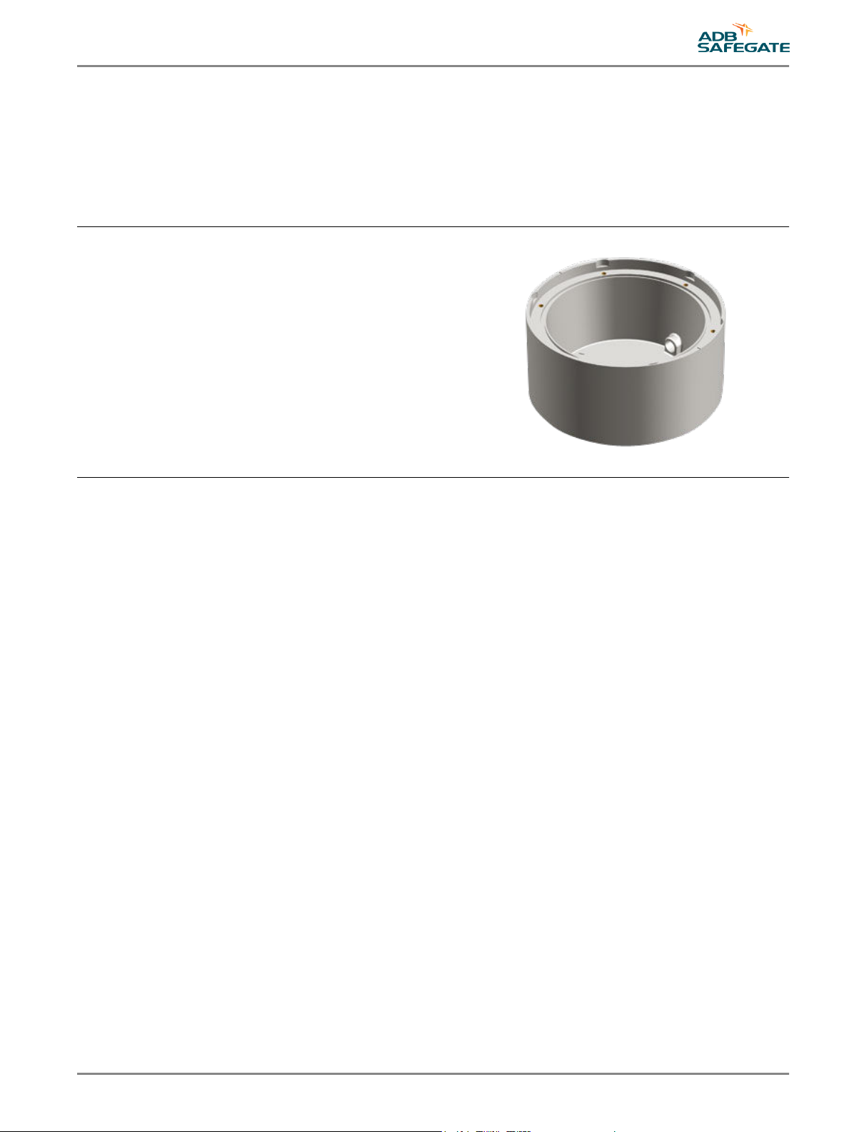
3.0 Introduction
RELIANCE™ Shallow Bases are receptacles for inset lights for site requirements at airports. The bases are 8” and 12” in size and
are compatible with ADB SAFEGATE inset lights. It may be possible to use with other manufacturers light units, however
compatibility must be checked separately.
3.1 RELIANCE Shallow Base 8”-135 mm Base 12”-150 mm
•Ground Fixing of 8" Inset Light Fittings (8" Base)
•Ground Fixing of 12" Inset Light Fittings (12" Base)
3.2 Delivery of units
To meet every customers individual requirements, Base 8”/12” are delivered without basic accessories such as, cable-glands,
cables, wiring protection tubes earth fixing screws and nuts. Basic accessories and electrical connection kits for Base 8”/12”
must be ordered separately.
3.3 Overview of unit types
The different types of shallow bases supplied allow direct mounting of 8” and 12” inset light fittings. Options available for
bases do not affect what type of light unit that can be used. The difference is the type of cabling system and the light fitting
fixing system to be utilized (Metric/UNC, Bolts/Nuts).
3.4 Base options
This section describes the options available for bases. It is possible for options to be combined. For more information, contact
ADB SAFEGATE.
UM-0106, Rev. 1.0, 2019/12/19 7
Copyright © ADB Safegate, All Rights Reserved
Product Description
Base
8-135 = 8” base, 135 mm depth
12-150 = 12” base, 150 mm depth
Cable entry
0 = Bottom-hole version1
2 = 2 open cable entries on side2
3 = 2 open cable entries on side3
Version
S = Stud bolt version4
T = Insert thread version
Stud bolt
M = Metric threads (M10)
U = UNC threads (UNC 3/8”)
Notes
1 No cable side entries.
2 No bottom hole, applicable for accessory kit 3.
3 No bottom hole, applicable for accessory kit 1 and 2.
4 Only available with metric threads.
X XXX X X X-
Note
For more information about base accessories, see data sheet for Base 8”-135 mm and Base 12”-150 mm.
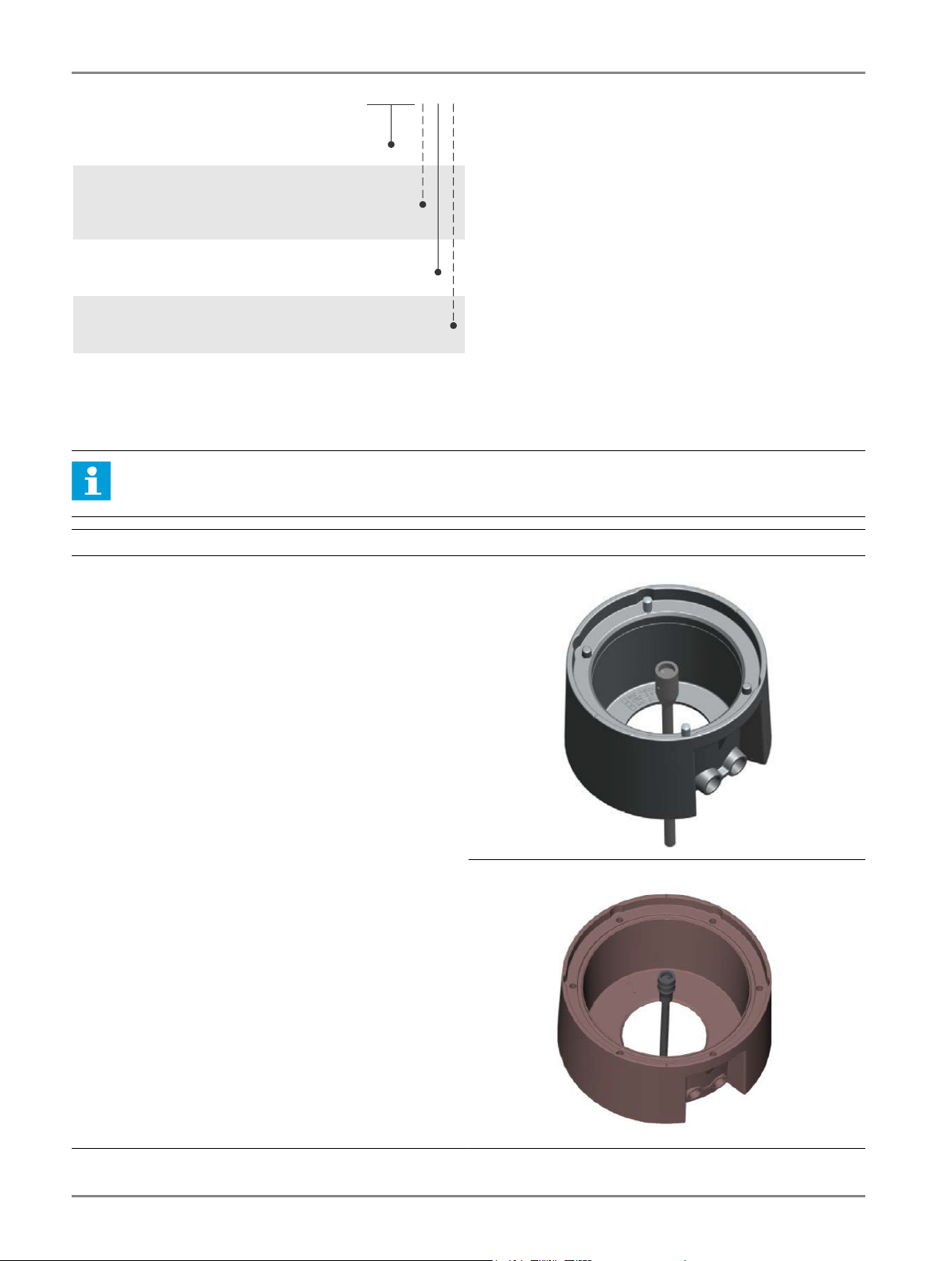
Base options Image examples
Base 8”-135-0-X-X
Base 12”-150-0-X-X
The option includes:
0 – Ø100 mm (8" bases), Ø130 mm (12" bases) bottom entry for
cables. This option is for cabling in the field with buried
conducts.
Figure 1: Bottom entry for 8” base
Figure 2: Bottom entry for 12” base
RELIANCE Shallow Base
Introduction
8
Copyright © ADB Safegate, All Rights Reserved
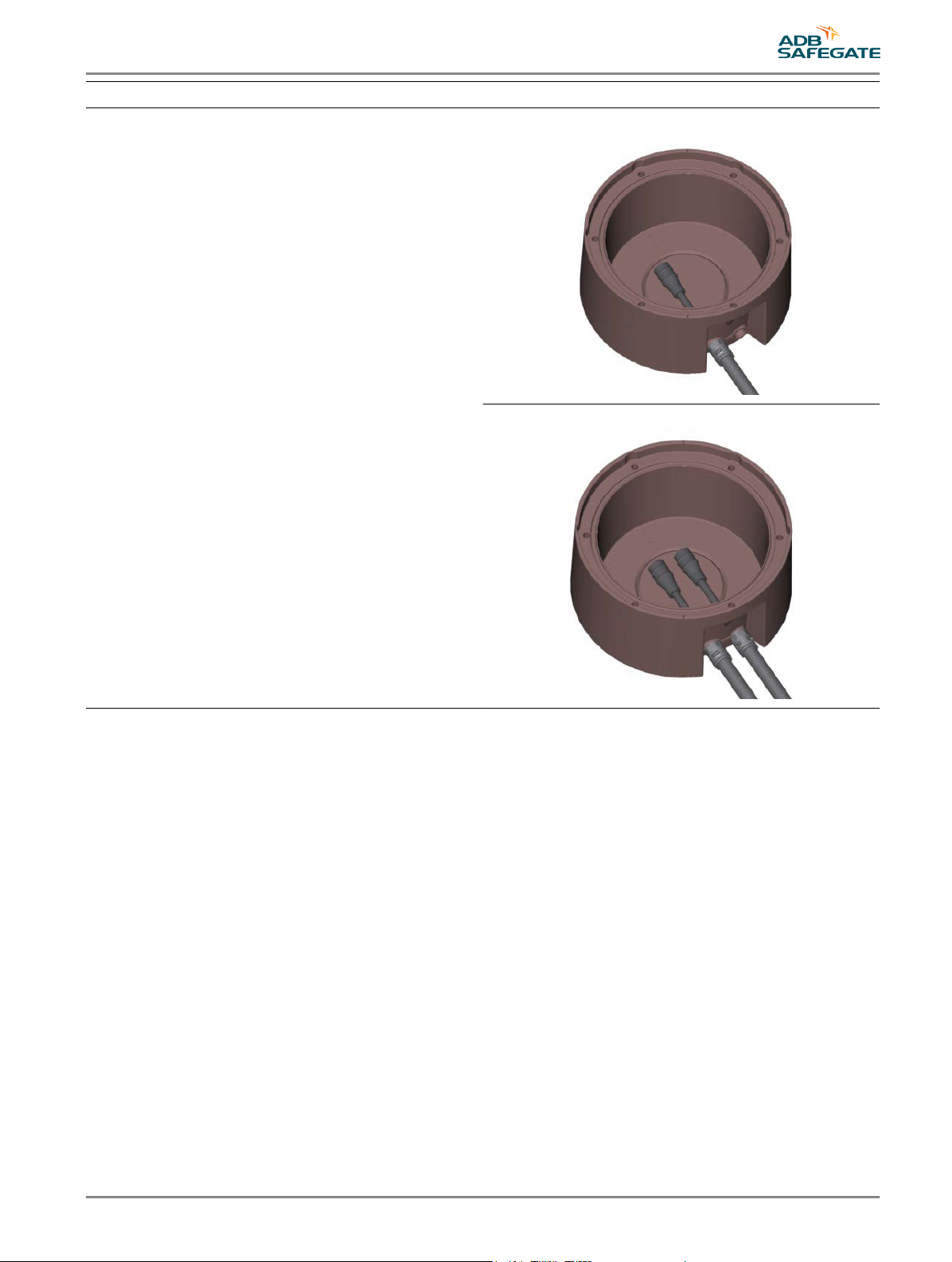
Base options Image examples
Base 8”-135-2-X-X
Base 12”-150-2-X-X
The option includes:
2 – 2-side entries for cables for cabling in the field with saw cuts/
grooves and two secondary cables (Ø 10-14 mm).
One cable:
•1 x Cable connector kit, cable and connector
•1 x Obstruction packer
Two Cables:
•2 x Cable connector kit, cables and connectors
Figure 3: 2-side entry for 12” base – One cable
Figure 4: 2-side entries for 12” base – Two cables
UM-0106, Rev. 1.0, 2019/12/19 9
Copyright © ADB Safegate, All Rights Reserved

Base options Image examples
Base 8”-135-3-X-X
Base 12”-150-3-X-X
The option includes:
3 – 2-side entries for cables (without plastic tube) for cabling in
the field with saw cuts/grooves and one or two secondary cables.
One cable:
•1 x Cable gland system
•1 x Obstruction packer
Two Cables:
•2 x Cable gland systems
Figure 5: 2-side entries for 8” base – One cable
Figure 6: 2-side entries for 8” base – Two cables
RELIANCE Shallow Base
Introduction
10
Copyright © ADB Safegate, All Rights Reserved
Table of contents
Other ADB Safegate Lighting Equipment manuals

ADB Safegate
ADB Safegate AXON User manual

ADB Safegate
ADB Safegate RELIANCE L-861T User manual

ADB Safegate
ADB Safegate L-862E User manual

ADB Safegate
ADB Safegate RELIANCE Series User manual

ADB Safegate
ADB Safegate L-858 AGSF Series User manual

ADB Safegate
ADB Safegate REIL-L User manual

ADB Safegate
ADB Safegate ERES User manual

ADB Safegate
ADB Safegate RELIANCE Guidance Sign User manual

ADB Safegate
ADB Safegate RELIANCE User manual

ADB Safegate
ADB Safegate UEL-1-150 User manual


