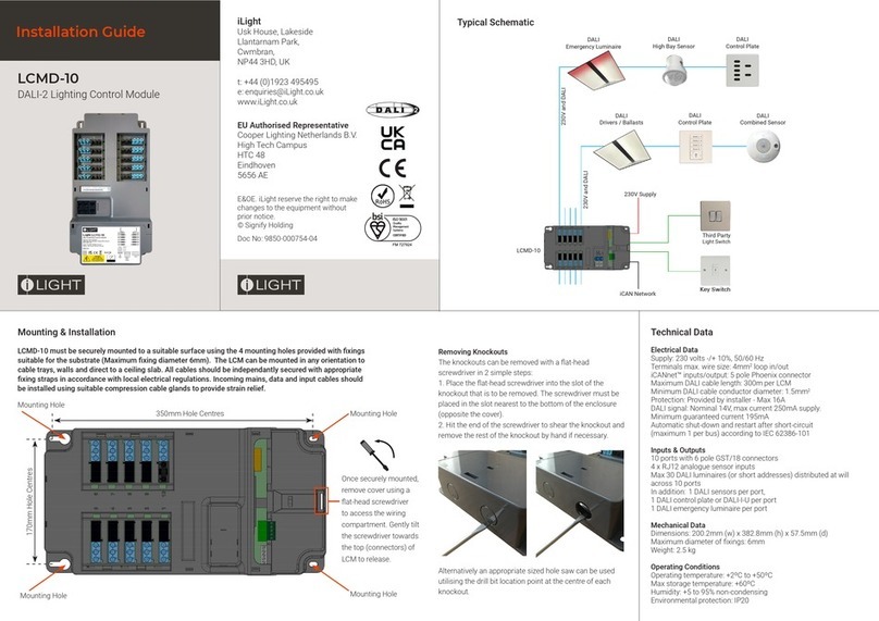
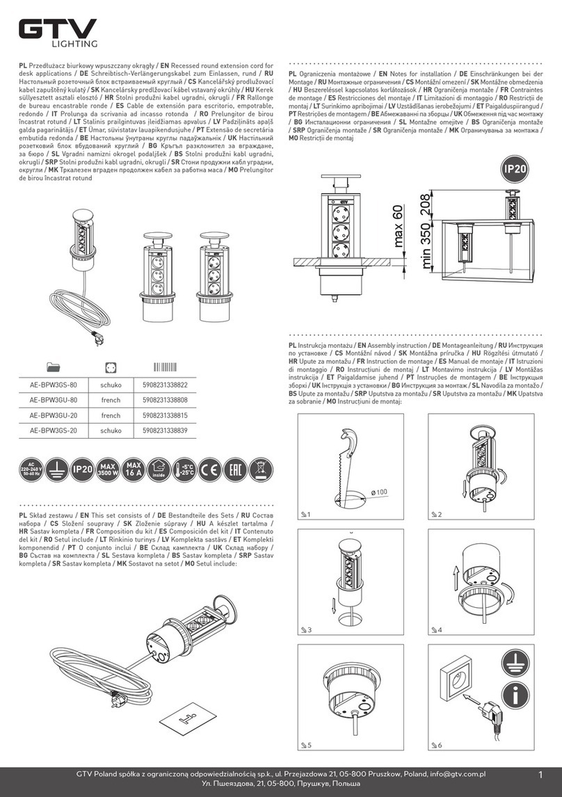
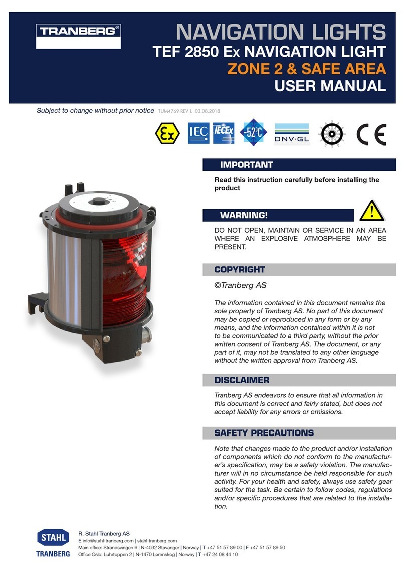
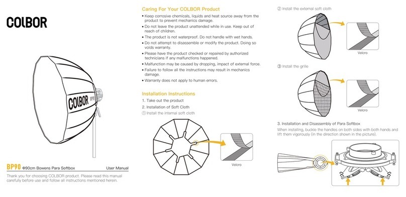
ADB PVL IP54 User manual

AM.04.265e Edition 1.1
Instruction Manual
Guidance Sign
Type PVL IP54

2
© ADB
This manual or parts thereof may not be reproduced, stored in a retrieval system, or transmitted,
in any form or by any means, electronic, mechanical, photocopying, recording, nor otherwise,
without ADBs prior written consent.
This manual could contain technical inaccuracies or typographical errors.
ADB reserves the right to revise this manual from time to time in the contents thereof without
obligation of ADB to notify any person of such revision or change.
Details and values given in this manual are average values and have been compiled with care.
They are not binding, however, and ADB disclaims any liability for damages or detriments
suffered as a result of reliance on the information given herein or the use of products, processes
or equipment to which this manual refers. No warranty is made that the use of the information or
of the products, processes or equipment to which this manual refers will not infringe any third
party’s patents or rights. The information given does not release the buyer from making their own
experiments and tests.
ADB Address: Leuvensesteenweg 585, B-1930 Zaventem, Belgium
Tel.: +32 2 722 17 11, Fax: +32 2 722 17 64
Email: marketing@adb-air.com
Internet: www.adb-air.com

AM.04.265e - Edition 1.1 3
Table of contents
1. About this manual
1.1. How to work with the manual ..............................................................................................................5
1.2. Record of changes..............................................................................................................................5
1.3. Abbreviations and terms .....................................................................................................................6
1.4. Icons used in the manual ....................................................................................................................6
2. Safety
2.1. Use......................................................................................................................................................7
2.2. Safety symbols....................................................................................................................................7
2.3. Skilled personnel.................................................................................................................................8
2.4. Liability ................................................................................................................................................8
2.5. Installation...........................................................................................................................................8
2.6. Fasteners ............................................................................................................................................9
2.7. Operation ............................................................................................................................................9
2.8. Action in the event of an equipment malfunction ................................................................................9
2.9. Maintenance and repair ....................................................................................................................10
2.10. Breakable coupling ...........................................................................................................................10
2.11. CE certification..................................................................................................................................10
2.12. Guarantee .........................................................................................................................................10
3. Description
3.1. Overview ........................................................................................................................................... 11
3.2. Intended use ..................................................................................................................................... 11
3.3. Variants of equipment ....................................................................................................................... 11
4. Installation
4.1. Inspect on delivery ............................................................................................................................13
4.2. Store..................................................................................................................................................13
4.3. Install according to standards ...........................................................................................................13
4.4. Overview of components required for installation .............................................................................13
4.5. Installation examples ........................................................................................................................14
4.6. Determine location of equipment ......................................................................................................16
4.7. Install concrete foundation ................................................................................................................16
4.8. Install transformer housing (series circuit only).................................................................................16
4.9. Install equipment...............................................................................................................................18
4.10. Install the tether (Option) ..................................................................................................................18
4.11. Electrical connection through leg (option).........................................................................................19
4.12. Install electrical connection ...............................................................................................................20
4.13. Install anti-bird deterrent (option) ......................................................................................................21
5. Maintenance
5.1. Preventive maintenance schedule ....................................................................................................23
5.2. Open equipment ...............................................................................................................................24
5.3. Close equipment ...............................................................................................................................24
5.4. Part replacement...............................................................................................................................25
6. Troubleshooting
6.1. Troubleshooting guide.......................................................................................................................31

4AM.04.265e - Edition 1.1
7. Technical data
7.1. Specifications ....................................................................................................................................33
7.2. Electrical wiring and PCB settings ....................................................................................................40
7.3. Exploded view and components .......................................................................................................43
7.4. Possible hardware for installation .....................................................................................................45
7.5. Possible tools for installation.............................................................................................................46
7.6. Ambient conditions............................................................................................................................46

AM.04.265e - Edition 1.1 5
About this manual
1 About this manual
The manual shows the information necessary to:
-install
- carry out maintenance
- carry out troubleshooting
on the PVL guidance sign, in the manual referred to as the equipment.
1.1 How to work with the manual
1. Familiarize yourself with the structure and content.
2. Carry out the actions completely and in the given sequence.
1.2 Record of changes
Edition Editor Check Date Description
1.0 MR WGR,
TWE,
THA,
MA,
01/2014 New manual IP54 version
1.1 TWE WGR,
NBU
10/2015 Update for new parts and minor changes.

6AM.04.265e - Edition 1.1
About this manual
1.3 Abbreviations and terms
1.4 Icons used in the manual
For all WARNING symbols, see § 2.2.
Term or abbreviation Description
AGL Airfield Ground Lighting
CCR Constant Current Regulator
FAA Federal Aviation Administration
Fastener Generic term for an item that holds the equipment together or that
holds the equipment on its mounting support, e.g. nut, bolt, washer
FOD Foreign Object Debris
ICAO International Civil Aviation Organisation
IEC International Electrical Committee
IP Ingress protection
ISO International Standardization Organisation
Light source This can be a LED, a fluorescent lamp or an halogen lamp. The type
depends on the type of equipment.
LED Light Emitting Diode
Mounting support Any mounting interface for elevated lights. It can be a piece of
equipment permanently installed in or on the ground, on which the
light is installed. It can be a shallow or deep base. It can be with or
without adapter ring.
PCB Printed Circuit Board
UNC Unified Thread Standard
VOR check-point Very high Frequency Omni directional Range check-point. A point
on the aerodrome where there is sufficient signal strength from a
VOR to check the VOR equipment on the aircraft.
CAUTION
Can cause damage to the
equipment.
NOTE
Gives further information.
TIP
Gives information on how to carry
out or to understand the
instruction or information more
easily.

AM.04.265e - Edition 1.1 7
Safety
2 Safety
Read all warnings carefully. Failure to do so may result in personal injury, death, or property
damage.
2.1 Use
To use the equipment safely:
Refer to the International Standard IEC 61820, Electrical installation for lighting and
beaconing of aerodromes - Constant current series circuits for aeronautical ground lighting -
System design and installation requirements, and to the International Standard IEC 61821,
Electrical installations for lighting and beaconing of aerodromes - Maintenance of
aeronautical ground lighting circuits for instructions on safety precautions.
See FAA Advisory Circular AC 150/5340-26, Maintenance of Airport Visual Aids Facilities,
for additional instructions on safety precautions.
Observe all safety regulations. To avoid injuries, always remove power prior to making any
wire connections and touching any live part. Refer to the International Standards IEC 61820
and IEC 61821.
In addition for a parallel power supply also take into account the International Standard IEC
60598 (for class I equipment).
Read and become familiar with the general safety instructions provided in this chapter
before you install, operate, maintain or repair the equipment.
Read and carefully follow the instructions given throughout this manual before installing,
operating, maintaining, or repairing the equipment.
Store this manual within easy reach of personnel installing, operating, maintaining or
repairing the equipment.
Follow all applicable safety procedures required by your company, industry standards, and
government or other regulatory agencies.
Obtain and read Material Safety Data Sheets (MSDS) for all materials used.
2.2 Safety symbols
Become familiar with the safety symbols presented in this chapter. These symbols will alert you
to safety hazards and conditions that may result in personal injury, death, or property and
equipment damage.
WARNING 1: Failure to observe this warning may result in personal injury, death, or
equipment damage.
WARNING 2: Risk of electrical shock. Disconnect equipment from line voltage.
Failure to observe this warning may result in personal injury, death, or equipment
damages.
WARNING 3: Wear personal protective equipment. Failure to observe may result in
serious injury.
WARNING 4: Do not touch. Failure to observe this warning may result in personal
injury, death, or equipment damage.

8AM.04.265e - Edition 1.1
Safety
2.3 Skilled personnel
The term skilled personnel is defined here as individual who thoroughly understand the
equipment and its safe operation, maintenance, and repair. Skilled personnel are physically
capable of performing the required tasks, familiar with all relevant safety rules and regulations
and have been trained to safely install, operate, maintain, and repair the equipment. It is the
responsibility of the company operating the equipment to see that its personnel meet these
requirements.
2.4 Liability
ADB cannot be held responsible for injuries or damages resulting from non-standard, unintended
uses of its equipment. The equipment is designed and intended only for the purpose described in
the manual. Uses not described in the manual are considered unintended uses and may result in
serious personal injury, death or property damage.
Unintended uses includes the following actions:
Making changes to equipment that have not been recommended or described in this
manual or using parts that are not genuine ADB replacement parts or accessories.
Failing to make sure that auxiliary equipment complies with approval agency requirements,
local codes, and all applicable safety standards if not in contradiction with the general rules.
Using materials or auxiliary equipment that are inappropriate or incompatible with your ADB
equipment.
Allowing unskilled personnel to perform any task on or with the equipment.
2.5 Installation
Read the installation section of all system component manuals before installing your equipment.
A thorough understanding of system components and their requirements will help you install the
equipment safely and efficiently.
Allow only skilled personnel to install ADB and auxiliary equipment. Use only approved
equipment. Using unapproved equipment in an approved system may void agency
approvals and will void the warranty.
Make sure all equipment is rated and approved for the environment in which you are using
it.
Follow all instructions for installing components and accessories.
Install all electrical connections to local code provided they are not in contradiction with the
general rules.
Use only electrical wire of sufficient gauge and insulation to handle the rated current and
voltage demand. All wiring must meet local codes.
Route electrical wiring along a protected path. Make sure they will not be damaged by
moving equipment and animals (e.g. rodents).
Protect components from damage, wear, and harsh environment conditions.
Allow ample room for maintenance, panel accessibility (power products), and cover removal
(power products).
Protect equipment with safety devices as specified by applicable safety regulations.
If safety devices must be removed for installation, install them immediately after the work is
completed and check them for proper functioning.
WARNING
Use of the equipment in ways other than described in the catalogue leaflet
and the manual may result in personal injury, death, or property and
equipment damage. Use this equipment only as described in the manual.
WARNING
Failure to follow these safety procedures can result in personal injury or
death.

AM.04.265e - Edition 1.1 9
Safety
2.6 Fasteners
Example It is possible to insert a 3/8” UNC screw in a M10 threaded hole. However, such a combination
damages the female thread and does not ensure a correct fastening. The screw could loosen
under the influence of aircrafts that roll over. The use of incorrect screws can lead to either
damage to the thread in the mounting support or to an incorrect fixation of the equipment.
2.7 Operation
Only skilled personnel, physically capable of operating the equipment and with no impairments in
their judgment or reaction times, should operate this equipment.
Read all system component manuals before operating the equipment. A thorough understanding
of system components and their operation will help you operate the equipment safely and
efficiently.
Before starting this equipment, check all safety interlocks and protective devices such as
panels and covers. Make sure all devices are fully functional. Do not operate the equipment
if these devices are not working properly. Do not deactivate or bypass automatic safety
interlocks or locked-out electrical disconnects or pneumatic valves.
Never operate equipment with a known malfunction.
Do not attempt to operate or service electrical equipment if standing water is present.
Use the equipment only in the environments for which it is rated. Do not operate the
equipment in humid, flammable, or explosive environments unless it has been rated for safe
operation in these environments.
Never touch exposed electrical connections on equipment while the power is ON. Make
sure the exposed electrical connections are proven to be dead.
2.8 Action in the event of an equipment malfunction
Do not operate a system that contains malfunctioning components. If a component malfunctions,
turn the system OFF immediately.
1. Disconnect and lock out electrical power.
2. Allow only skilled personnel to make repairs. Repair or replace the malfunctioning
component according to instructions provided in its manual.
WARNING
Only use fasteners of the same type as the one originally supplied with
the equipment.
Always tighten the fasteners to the recommended torque. Use a
calibrated torque wrench and apply the recommended adhesive type.
Obey the instructions of the adhesives necessary for the fasteners.
If this is not the case, this may cause the fasteners to loosen, damage the
equipment, potentially to loosen the equipment. This can lead to a highly
dangerous situation of FOD, with potential lethal consequences.

10 AM.04.265e - Edition 1.1
Safety
2.9 Maintenance and repair
Allow only skilled personnel to perform maintenance, troubleshooting, and repair tasks. Only
persons who are properly trained and familiar with ADB equipment are permitted to service the
equipment.
Always use safety devices when working on the equipment.
Follow the recommended maintenance procedures in your equipment manuals.
Do not service or adjust any equipment unless another person trained in first aid and Cardio
Pulmonary Resuscitation (CPR) is present.
Connect all disconnected equipment ground cables and wires after servicing equipment.
Ground all conductive equipment.
Use only approved ADB replacement parts. Using unapproved parts or making unapproved
modifications to equipment may void agency approvals, impair specified performance and
create safety hazards.
Check interlock systems periodically to ensure their effectiveness.
Do not attempt to service electrical equipment if standing water is present. Use caution
when servicing electrical equipment in a high-humidity environment.
Use tools with insulated handles when working with electrical equipment.
2.10 Breakable coupling
A: Mounting leg
B: Weakening groove
C: Mounting flange
The equipment is mounted on mounting legs.
The mounting legs have a weakening groove,
which serves as a breakable coupling.
Expansion bolts secure the mounting flanges to
the foundation.
2.11 CE certification
The equipment is CE certified. It means that the product complies with the essential
requirements concerning health and safety. The directives that have been taken into
consideration in the design are available on written request to ADB.
2.12 Guarantee
LED Products of ADB Airfield Solutions manufactured and sold by ADB or its licensed
representatives, meet the corresponding requirements of FAA, ICAO and IEC.
Refer to the document ‘General Conditions for Deliveries and Services by ADB’.
C
B
A

AM.04.265e - Edition 1.1 11
Description
3 Description
3.1 Overview
You can find a complete overview of the equipment in all available versions in the chapter 7.
3.2 Intended use
On civil aerodromes:
- Mandatory instruction signs
- Information signs
- VOR check-point sign
3.3 Variants of equipment
The equipment can be also supplied with these options:
- An additional safety switch. The safety switch allows safe servicing on the equipment when
the safety switch is set to the OFF position. The safety switch is mainly used for equipments
that are supplied directly from the mains supply with 230 V AC.
- Supply cables that go through the mounting legs.
- A tether to secure the equipment.
The manual does not show these variants in detail.

12 AM.04.265e - Edition 1.1
Description

AM.04.265e - Edition 1.1 13
Installation
4 Installation
4.1 Inspect on delivery
1. Inspect all packings for visible damage.
2. Open every damaged box and inspect the contents for damage.
3. Immediately fill a claim form with the carrier if any equipment is damaged.
4. Store the equipment in its original packing in a protected area.
4.2 Store
1. Store the equipment in its original packing in a protected area.
4.3 Install according to standards
1. See these standards:
- ICAO Annex 14, volume 1;
- ICAO Airport Design Manual, parts 4 and 6, section that refer to signs;
- ICAO Airport Design Manual, part 5 ‘Electrical Systems’;
- IEC 61820 and 61821.
2. For a parallel power supply, see also:
- IEC 61950 (low voltage directive);
- IEC 60598-1 (class I equipment).
4.4 Overview of components required for installation
- Assembled equipment;
- Secondary cable(s) and possibly a flexible conduit.
- Series circuit: 2-core cable with FAA plug (supplied with the equipment);
- Parallel circuit: 2-core cable with earthing wire (not supplied with the equipment);
- Hardware for installation. See § 7.4.
- Tools for installation. See § 7.5.
- Series transformers. See § 7.1. Series circuit only.
- Optional: security cable or tether.
WARNING
The equipment meets IEC 60598-1. Make sure that you make all electrical
connections accordingly.
Note
- The figures show a typical connection that uses an ADB conduit elbow.
- The procedures in this chapter show the complete information for a
series power supply. For a parallel power supply, the procedures are
similar. The difference is that there is no series transformer necessary.
The power supply cable that comes from a derivation box or connection
box is directly connected to the power adaptor within the equipment.
WARNING
Do not damage the cable insulation.
CAUTION
Do not unpack the equipment before it is at the installation site to avoid
damage due to transportation and handling.

Installation
Installation AM.04.265e - Edition 1.1
4.5 Installation examples
Example 1
Items: A: Ground level
B: Primary series loop
C: Transformer pit or housing with drainage
to ground or drain
D: Weather proof sealing and filling
E: Conduit elbow
F: M10 expansion bolt (3 per flange)
G: Concrete block
H: Sign
I: Message
J: Frost line
Measurements: X1: 748 mm
X2: 700 mm
X3: minimum 300 mm
X4: 100 mm
X5: 644 mm
Y1: 640 mm
Y2: 600 mm
Y3: 25 mm
Y4: minimum 575 mm
Y5: minimum 100 mm
Z1: 230 mm horizontal
Z2: minimum 830 mm
Z3: minimum 300 mm
Z4: 230 mm
Z5: minimum 300 mm
Z6: 50 mm
V1: diameter 145 mm
V2: angle 120 degrees
V3: 2 cm per 1 m
Note
These examples show general installation details. The drawings are for
instructional use only, do not use them as construction drawings for specific
projects.
6048
A
Y1
Y1
Z1
X1
V1
V2
X3
X4
X5 X3
V2
V1
Z6 Z4
Z5
Z3
Z2
G
Y4
J
Y5
V3
A
Y3
Y2
X1
X2
I
C
B
A
H
D
E
F
NOTE
- Depending on the type of power supply (series or parallel), the
transformer pit contains the series transformer or a derivation box.
- You must install one transformer per series power supply. Refer to
section 7.1.3 Power consumption series supply to choose the size of the
transformer.

Installation
AM.04.265e - Edition 1.1 15
Example 2
Items: A: Base L-867B or transformer pit
B: Weather proof sealing and filling
C: M10 expansion bolt (3 per flange)
D: Conduit elbow
E: Concrete block
F: Ground level
G: Frost line
H: Sign
I: Message
J: Electrical connection through leg (option)
Measurements: X1: 2100 mm
X2: 36 mm
X3: 1900 mm
X4: 750 mm
X5: 500 mm
X6: 1023 mm
X7: 1023 mm
X8: 140 mm
X9: 923 mm
X10: 923 mm
X11: 300 mm
X12: 100 mm
X13: 140 mm
X14: 36 mm
Y1: 840 mm
Y2: minimum 575 mm
Y3: minimum 100 mm
Z1: 50 mm
V1: diameter 60 mm
V2: diameter 145 mm
V3: angle 120 degrees
07-25
CAT II
X13
V2
V3
V2
X14 I
3 x M10
X8 X9 X10 X11
X4 X5
X12
Z1
H
V1
X6
X12
H
X7
Z1 II
F
X3
X2
X1
H
Y2
Y1
Y3
A
I
B
C
DJ
E
G
NOTE
- Depending on the type of power supply (series or parallel), the
transformer pit contains the series transformer or a derivation box.
- You must install one transformer per series power supply. Refer to
section 7.1.3 Power consumption series supply to choose the size of the
transformer.

16 AM.04.265e - Edition 1.1
Installation
4.6 Determine location of equipment
1. Determine the perpendicular distance for
the defined taxiway or runway pavement
edge to the nearest edge of the equipment.
Use table 5-5 of ICAO Annex 14, Volume 1.
2. In the case of adjacent equipment, make
sure that:
- The equipment is separated with a
distance X = 36 mm;
- The centre lines of adjacent mounting
legs are separated with a distance Y
= 140 mm.
3. Determine the exact location and
orientation on site.
4. Make sure that the Airport Authority approves the exact location.
4.7 Install concrete foundation
Prepare 1. Define the dimensions of the concrete foundation block, based on several factors among
which:
- The length of the equipment;
- The height of the equipment;
- The bearing of the soil;
- The stability of the soil;
- The frost line: the depth of the foundation must be more than the depth of the frost line.
2. Use one-piece concrete block for adjacent equipment.
Choose casting
method
1. Choose between:
- Cast the concrete blocks in situ;
- Use pre-fabricated concrete blocks.
2. Accurately level and smoothen the top surface of the concrete foundation.
4.8 Install transformer housing (series circuit only)
Each equipment requires one to three series transformers. See § 7.1. A series transformer must
be installed in a transformer housing, adjacent to the sign foundation.
Note
Also take into consideration the unobstructed equipment legibility and
the protection from direct exhaust blast.
Y
X
Note
The drawings in § 4.6 show typical examples.
CAUTION
If this is not the case, the concrete can crack under the pressure of the
expansion bolts of the adjacent (outer) legs.

AM.04.265e - Edition 1.1 17
Installation
Define location of
transformer
housing
A Equipment
B Transformer housing location
C Primary cable
1. Make sure the transformer housing is
adjacent to the sign foundation. The figure
shows some possible arrangements.
2. Make sure that you can easily access the
transformer and do not need to remove the
equipment.
Choose
transformer
housing type
1. Choose between:
- Transformer pit;
- FAA steel base.
Install
transformer pit A Load bearing cover
B Equipment
C Conduit elbow
D Typical water drainage hole
E Series transformer
F Ground level
1. Install the transformer pit. The figure shows
a possible installation layout.
2. Make sure that the space between the
centres of the conduit elbow and the
adjacent mounting leg (X) is minimum 185
mm.
3. Make sure the space between the side of
the base and the adjacent expansion bolts
of the equipment is large enough (recommended minimum 100 mm).
Install FAA steel
base A Bolted steel cover, 10 mm thickness
B Conduit coupling
C Equipment
D Flexible conduit
E 2” or 3” diameter entry for primary cables
F Water drainage pipe (optional)
G FAA L867 base, diameter 12, depth 400 or
610 mm
H Ground level
1. Install the FAA steel can. The figure shows
a possible installation layout.
2. Make sure the space between the side of
the base and the adjacent expansion bolts
of the equipment is large enough
(recommended minimum 100 mm).
BA
I
II
III
AAA
BB B
A
BC
C
C
AA
25
E
AF B
D
C
X
25-
G
BAH
C
D
F
E

18 AM.04.265e - Edition 1.1
Installation
4.9 Install equipment
Prepare 1. Put the equipment on the concrete foundation.
2. Align the equipment, especially in the case of adjacent equipments.
3. Mark the position of the fixation holes. Use the drill template. See § 7.5.
4. Remove the equipment.
5. Drill the fixation holes.
Install 1. Put the equipment above the fixation holes.
2. Tighten the expansion bolts (A) with a torque
of 27 Nm.
3. Install the tether (B) (Option).
4. Remove the protection film from the legend
panel.
4.10 Install the tether (Option)
1. Put the fastener (A) through these items:
- Hole (B)
- Washer (C)
-Nut(D)
2. Tighten the nut (D).
3. Install these parts:
- Bracket (E)
- washer (F)
-Nut(G)
4. Tighten the nut (G) with a torque of 27 Nm.
Note
If you do not use the drill template, the figure in § 7.1.2 shows the
dimensions.
Note
This procedure describes the use of expansion bolts. You can also use
bent anchor bolts or resin bolts. Refer to your bolt supplier for
installation instructions.
B
A
BA
E
F
G
DC

AM.04.265e - Edition 1.1 19
Installation
4.11 Electrical connection through leg (option)
1. Prepare a hole (A) with a diameter of
63 mm.
2. Pull the secondary cable (B) through the
leg (C).
Note
The secondary cable is not
supplied with the equipment
C
A
B

20 AM.04.265e - Edition 1.1
Installation
4.12 Install electrical connection
Enter cable into
the equipment
1. Open the equipment. See § 5.2.
2. Slip the flexible conduit over the cable, if used.
3. Enter the supply cable(s) into the equipment through the compression gland(s) or the
nipple(s) at the bottom of the equipment or through the compression gland in the leg, see §
4.11.
Connect cable to
equipment
For an overview of the location of the input terminals and glands, see § 7.2.3.
Parallel power supply
1. Connect the cables (A) to the input
terminals 1 and 5 of the connector (C).
Connect the earth cable (B) to input
terminal 3 of the connector (C).
Series power supply
1. Connect the cables (A) to the left
receptable (B) and the right receptable (C)
of the connector.
Note
We recommend to run the cable either through a flexible conduit or
through the left outer leg for protection against damage caused by
rodents and UV-radiation.
1
2
3
4
5
6
CA
B A
A
A
B
C
This manual suits for next models
1
Table of contents
Other ADB Lighting Equipment manuals

