ADB EURODIM TWIN TECH User manual

Installation Manual
V 1.2
EURODIM Twin Tech
M 3213 1106.03.213
Lighting Technologies


EURODIM TWIN TECH
www.adblighting.com
Installation manual - Page 1
Version 1.2
INDEX
1. DELIVERY - UNPACKING ........................................................................................................... 3
2. DESCRIPTION.............................................................................................................................. 4
3. INSTALLATION............................................................................................................................ 5
3.1 Dimmer room......................................................................................................................... 5
3.1.1 Preparation ........................................................................................................................ 5
3.2 Ventilation of the dimmer room.............................................................................................. 6
3.2.1 Example No. 1 ................................................................................................................... 6
3.3 Installation of the cabinets..................................................................................................... 7
3.3.1 Tools for commissioning.................................................................................................... 7
3.3.2 Packaging .......................................................................................................................... 8
3.3.3 Lifting Eyes (Optional Accessory)...................................................................................... 8
3.3.4 Junction Plate (optional part)............................................................................................. 8
4. CONTRACTOR'S COMPARTMENT –SUPPLY ....................................................................... 10
4.1 Controller Electronics - CPU/ PSU crate............................................................................. 11
4.2 Supply voltage..................................................................................................................... 11
4.3 Supply busbar...................................................................................................................... 12
4.3.1 Protected Earth (PE)........................................................................................................ 13
4.4 Connecting power supply cables......................................................................................... 13
4.5 Ground and Earth Connections........................................................................................... 14
5. SEQUENTIAL DIAGNOSTICS (Optional)................................................................................. 15
5.1 Hardware installation........................................................................................................... 16
5.2 Mounting Procedure ............................................................................................................ 17
5.3 Finished installation............................................................................................................. 17
5.4 Software Installation ............................................................................................................ 18
5.5 Overview of the User Interface Menu items........................................................................ 20
5.6 TTD Management SOFTWARE.......................................................................................... 21
5.7 References and Element Codes ......................................................................................... 22
6. CONTRACTOR’S COMPARTMENT – OUTPUTS .................................................................... 23
6.1 Outputs to the loads ............................................................................................................ 24
6.2 Identification of the dimmers................................................................................................ 24
6.3 Load terminals for 4 x 2.5 / 3 kW modules.......................................................................... 24
6.4 Load terminals for 3 x 5 kW modules.................................................................................. 24
6.5 Load terminals for 2 x 3 kW fluo modules ........................................................................... 24
6.6 Load terminals for 10kW modules....................................................................................... 25
DMX and Ethernet terminals............................................................................................................. 26
6.6.1 DMX Connection –type of cable..................................................................................... 26
6.6.2 Pin numbering.................................................................................................................. 27
6.6.3 DIP switches SW1 –termination of the DMX data lines.................................................. 27
6.7 Local / Remote Controller selector switch CPU1 –CPU2 –Automatic .............................. 28
7. TTD HUMAN INTERFACE ......................................................................................................... 29
8. PLUG IN MODULES................................................................................................................... 31
8.1 DimSwitch - Thyristor Technology....................................................................................... 31
8.2 Sine Wave Technology........................................................................................................ 31
8.3 NON-DIM (Feed Through) modules.................................................................................... 31
8.4 Blank Panels........................................................................................................................ 31
8.5 Distribution of the dimmers over the phases....................................................................... 31
8.6 Protections –types, number of poles.................................................................................. 31
8.7 Dimmer module protection by HRC fuse............................................................................. 32

EURODIM TWIN TECH
www.adblighting.com
Installation manual - Page 2
Version 1.2
8.8 Dimmer protection by MCB ................................................................................................. 32
8.9 Residual Current Devices (RCD Ground Fault Protection)................................................. 32
8.10 Installing Dimmer Modules.................................................................................................. 33
8.11 CONTROLLER UNIT (CPU) - POWER SUPPLY UNIT (PSU)........................................... 34
8.12 BLANK MODULES.............................................................................................................. 35
8.13 MODULE LOCKS................................................................................................................ 36
9. CHARACTERISTICS.................................................................................................................. 37
9.1 Electrical characteristics...................................................................................................... 37
9.2 Physical characteristics....................................................................................................... 38
10. DMX NETWORK AND INTERCONNETCIONS ......................................................................... 39
10.1 Example 1: One DMX lighting desk, one CPU per EURODIM cabinet............................... 39
10.2 Example 2: One DMX lighting desk, two CPU’s per EURODIM cabinet............................. 39
10.3 Example 3: Two DMX lighting desks, one CPU per EURODIM cabinet ............................. 39
10.4 Example 4: Two DMX lighting desks, two CPU’s per EURODIM cabinet (case A) ........... 40
10.5 Example 5: Two DMX lighting desks, two CPU’S per EURODIM cabinet (case B)............ 40
11. Appendix B –Drawings............................................................................................................ 41
11.1 5000-35-650 EURODIM Twin Tech –Vertical Packaging (standard)................................. 41
11.2 3500.01.650 Power Modules 1 - 8 ...................................................................................... 42
11.3 3500.01.660 Power Modules 9 - 16 .................................................................................... 43
11.4 3500.01.670 Power Modules 17 - 24 .................................................................................. 44
11.5 3500.01.680 Power Modules 25 - 32 .................................................................................. 45
11.6 10 kW Module Connection .................................................................................................. 46
11.7 3650.00.311 PCB3031 DMX512 Connection...................................................................... 47
11.8 3650.00.311 PCB3031 Selector with Wiring....................................................................... 48
11.9 3500.01.710 OUTPUT TERMINALS FOR FLUO Modules................................................. 49
11.10 CE Certificate for EURODIM Twin Tech ............................................................................. 50
12. Appendix C–Power Supply for Thyristor Dimmers –Basic Principles for Safe Electrical
Design................................................................................................................................................... 51
12.1 Phase-control dimmers........................................................................................................ 51
12.2 Use ‘true rms’ voltmeters only ............................................................................................. 51
12.3 Current in the Neutral –Sine Wave..................................................................................... 51
12.4 Current in the Neutral –Dimmer Systems........................................................................... 52
12.5 Practical implications........................................................................................................... 52
12.5.1 Example No. 1............................................................................................................. 52
12.5.2 Example No. 2............................................................................................................. 52
12.5.3 Example No. 3............................................................................................................. 52
12.6 Main transformer, cables, switchgear, busbar systems ...................................................... 53
12.7 Voltage distortion and 'short-circuit voltage' of the main transformer.................................. 53
13. Appendix D: Specification of Magnetic Circuit Breakers (MCB).......................................... 54
14. CONFIGURATION TABLES ...................................................................................................... 55

EURODIM TWIN TECH
www.adblighting.com
Installation manual - Page 3
Version 1.2
1. DELIVERY - UNPACKING
Thank you for purchasing our EURODIM Twin Tech installation dimmer. We have designed
this installation dimmer to provide you with a superior professional dimmer in design and
engineering. We are confident that it will perform to our expectations for many years to come.
Upon delivery of your equipment, open the packaging carefully and examine the device. If
you observe any damage, contact the shipping company immediately and have your
complaint duly recorded. Please take pictures in order to prevent further misunderstandings.
The plug-in dimmer modules, Human (User) Interface and controller(s) are shipped
separately from the cabinet. You may rest assured that your equipment left our factory in
perfect condition. Check whether what you have received is in conformity with the delivery
notice and whether the notice is in conformity with your order.
In the event of any error, contact your shipper immediately to clarify the situation and receive
full satisfaction.
If you find nothing wrong, replace the material in the packing and store it in a warm place,
away from dust, humidity and mechanical hazards, while awaiting final installation.
Never leave the material unprotected on the work site.
Programming and setting up the cabinet (configuration) is described in a separate manual.
CAUTION!
Installation is entirely at your own risk. Read this installation manual from cover to cover
before attempting installation. Do not attempt installation unless you are suitably qualified.
Installation errors may endanger operators and cause system damage and failure. If you do
not understand a point in this manual, don’t guess. Contact ADB or one of our authorised
distribution partners for advice.
We recommend ordering commissioning through ADB or one of our authorised partners prior
energizing the system. Not following this recommendation may result in equipment damage
that may not be covered by your warranty!


EURODIM TWIN TECH
www.adblighting.com
Installation manual - Page 5
Version 1.2
3. INSTALLATION
3.1 Dimmer room
3.1.1 Preparation
Determine the dimensions of the dimmer room so as to place all EURODIM Twin Tech
cabinets easily. Provide for an open space of approximately 90 cm in front of the cabinets to
facilitate maintenance. Before attempting to move the rack(s) into the final position, check
access routes to the dimmer room for space to manoeuvre through doorways and around
corridor corners. The cabinets can be placed against a wall, side by side or back to back.
The supply cables and the load cables can enter the wiring compartment either from the top
or bottom of the cabinet. See drawing for size and location of cable entries.
Dimmer Room Requirements
A clean (not dusty) temperature-controlled environment.
Restricted public access to prevent any unauthorised tampering with the
dimmer settings.
Soundproofing or performance area separation to muffle ventilation fan noise.
Acoustic measurements are available from ADB Lighting Technologies.
Provide for a free space, minimum 30 cm above the EURODIM Twin Tech so
as to facilitate the exhaust airflow. If an optional “Silencer” is used, then more
space may be necessary. The dimensions and weight of the cabinets are
included in the Chapter “Characteristics”. Plan for fire extinguishers in
compliance with local regulations. The lighting of the area should be sufficient
for maintenance and inspection. A level of 300 lux is considered satisfactory.
Plan for mains outlets in the room, independent of the supply of the dimmers.
Plan for an Ethernet network to the control room and a cable for remote “CPU1 - CPU2”
selection (if applicable).
EURODIM Twin Tech cabinets are professional equipment and relevant safety rules are
applicable. EURODIM Twin Tech cabinets should be placed in areas that are accessible only
to persons responsible for maintenance, surveillance or repair of the equipment.
Please refer to local regulations and requirements.
Such an area should be located as close as possible to the stage or studio, in order to
reduce the length of the electrical cables, and therefore, the cost of installation. At the time of
installation of the cabinets in the area, it should be completely unobstructed; that is, that all
engineering work, wall or floor covering work, painting, electric lighting work, drilling, welding,
etc., must be completed.
Do not install the plug-in modules until all wiring installation is completed.
EURODIM Twin Tech has been designed to European standards for electrical switchgear
EN60439. It is CE marked. See chapter 11.10 CE Declaration Document for EURODIM Twin
Tech.

EURODIM TWIN TECH
www.adblighting.com
Installation manual - Page 6
Version 1.2
3.2 Ventilation of the dimmer room
The dimmer room should be dry at all times, free from dust and ventilated in such a manner
as to comply with the following:
-Relative humidity: 5% to 90% without condensation.
-Temperature between + 5 °C and + 35 °C (ideal: + 20 °C).
In order to size the air-conditioning equipment required for the dimmer room, refer to the
following dissipations:
-Cabinet electronics including 150 W global value for CPU(s), PSU and fans
-Thyristor modules:
o4 x 3 kW modules : 37 W per dimmer (worst case)
o3 x 5 kW modules : 69 W per dimmer (worst case)
o1 x 10 kW modules : 170 W per dimmer (worst case)
-Sinewave modules:
o4 x 2.5 kW modules : 60 W per dimmer (worst case)
-No-load losses of sine wave dimmers:
oSine wave dimmers have a no-load loss of approximately 4 W per dimmer.
In practice, you may consider a utility factor of 0.6: that is, on the average, 60% of the
dimmers are at full load, while 40% are off.
3.2.1 Example No. 1
A dimmer room with a EURODIM Twin Tech cabinet equipped with 128 thyristor dimmers of
3 kW and a second cabinet with 96 thyristor dimmers of 5 kW. The cabinets are fitted with a
back-up power supply for the processor unit. Utility factor = 0.6
1) Cabinet N°1
Electronics: 1 x 150 W
Dimmers 128 x 37 W x 0.6 = 2841 W
2) Cabinet N°2
Electronics: 1 x 150 W
Dimmers 96 x 69 W x 0.6 = 3974 W
ROOM TOTAL: 7115 W (1 W = 0.86 kcal/hour) or 6119 kcal/hour.
In this example, it will be necessary to evacuate approximately 7115 W of losses.
EURODIM TWIN TECH
www.adblighting.com
Installation manual - Page 7
Version 1.2
3.3 Installation of the cabinets
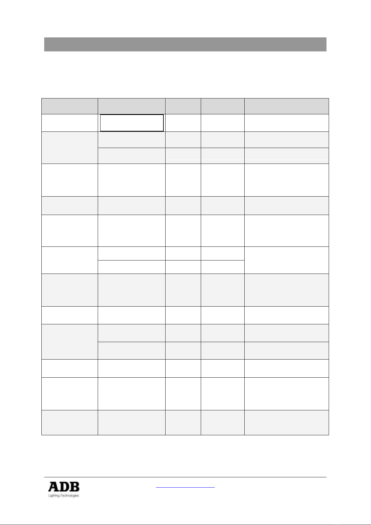
3.3.1 Tools for commissioning
Operation
Connection
Designation
Qty
Torque
Tools
Remove Doors
Pan Head Screw
M4x12 PZ
1
1,5 Nm
Screw Driver PZ2
Remove Card
Cage Dimmers
Pan Head Screw
M4x12 PZ
5
2 Nm
Screw Driver PZ2
Slotted Flat Head
Screw M4 x 12 PZ
16
1,5 Nm
Screw Driver PZ 2
Open Cables
aperture
In & Out
Pan Head Screw
M4x12 PZ
8
2 Nm
Screw Driver PZ 2
PE Connection
Power In
Nut M10
1
8 to 10 Nm
Metric Wrenches 17
Sequential
Diagnostics
(Optional)
Nut M 5 / Flat
Washers M 5 /
Helical Spring Lock
Washers M 5
2 of each
1,5 Nm
Metric Wrench 8
Input
Connection
(Bus Bar)
Nut M12
4
8 to 10 Nm
2 x Metric Wrenches 19
Bolt M12
4
8 to10 Nm
Output
Connection
(Output)
Terminal
Connection
Free Drive Screw
256
1,5 Nm
Flat Screw Driver 1 x 6, 5
(do not use power tools!)
PE connection
(Output)
Screws M4 x 8
128
1,5 Nm
Screw driver PZ 1
DMX
Connection
RJ 45
1
Phoenix MSTBVA
2,5 –6
6
0,5 Nm
Flat ScrewDriver 0,5 x3, 5
Ethernet
Connection
RJ 45
1
TTD Human
Interface
Nut M 4 / Flat
Washers M 4 /
Helical Spring Lock
Washers M 4
X4 (of
each)
1,5 Nm
Metric Wrench 7
Junction Plate
(Accessory)
Hex Cap Screw
M 16 x 25
4
3 Nm
Metric Wrenches 24
ADB recommend using Insulated Screwdriver.
EURODIM TWIN TECH
www.adblighting.com
Installation manual - Page 8
Version 1.2
3.3.2 Packaging
The cabinets are shipped on a wooden pallet (see attached drawing in Chapter 12:
5000-35-650).
Standard transport position is vertical; First open the top panel after removing the screws of
the side panels.
The control processors, TTD Human Interface and dimmer modules are packed separately.
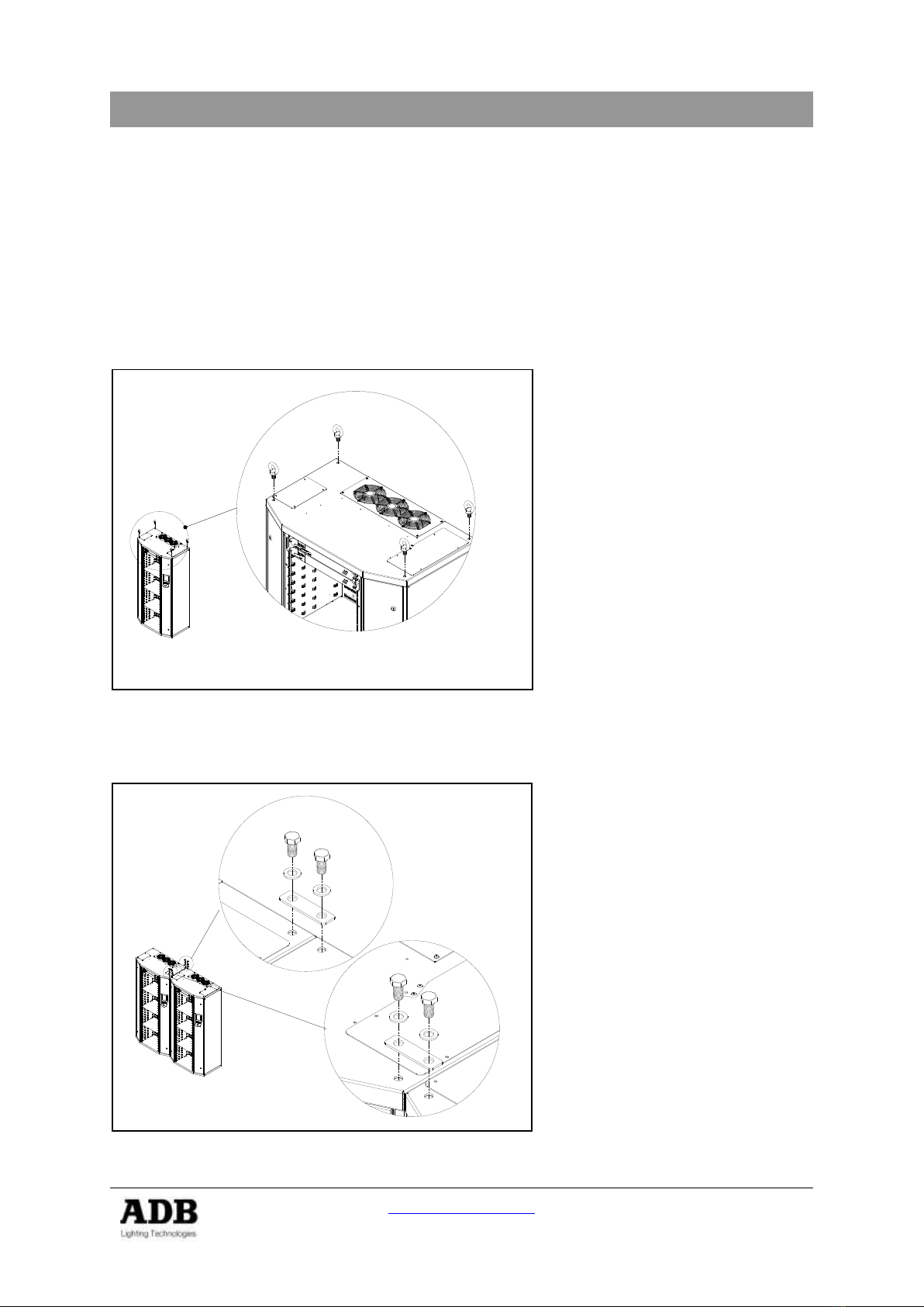
3.3.3 Lifting Eyes (Optional Accessory)
If the cabinet must be elevated with a crane, use 4 lifting eyes
TTD/CAB/LIFT kit including 4 Lifting Eyes.
3.3.4 Junction Plate (optional part)
With the optional junction plate two cabinets can be connected to guarantee permanent
fixation.
EURODIM TWIN TECH
www.adblighting.com
Installation manual - Page 9
Version 1.2
The weight and dimensions of the cabinets are included in Chapter “Characteristics”. Prior to
positioning each cabinet, ensure that the floor is flat and horizontal to ensure a good weight
distribution.
It is the responsibility of the system integrator or installer to check if the cabinet weight load
can be supported by the building structure!
After you have positioned the cabinets:
-Do not remove the plastic, so as to keep a protection during the cabling works.
-Cut the plastic to have an access to the cabling areas.
-Remove the doors of the contractor's areas by simply opening the door hinges.
CAUTION! The doors are grounded / earthed.
Gently remove this grounding connection WHICH MUST BE
RESTORED when the door is eventually put back in place.
During the cabling works, leave the doors in a clean area and covered
with a protection.

EURODIM TWIN TECH
www.adblighting.com
Installation manual - Page 10
Version 1.2
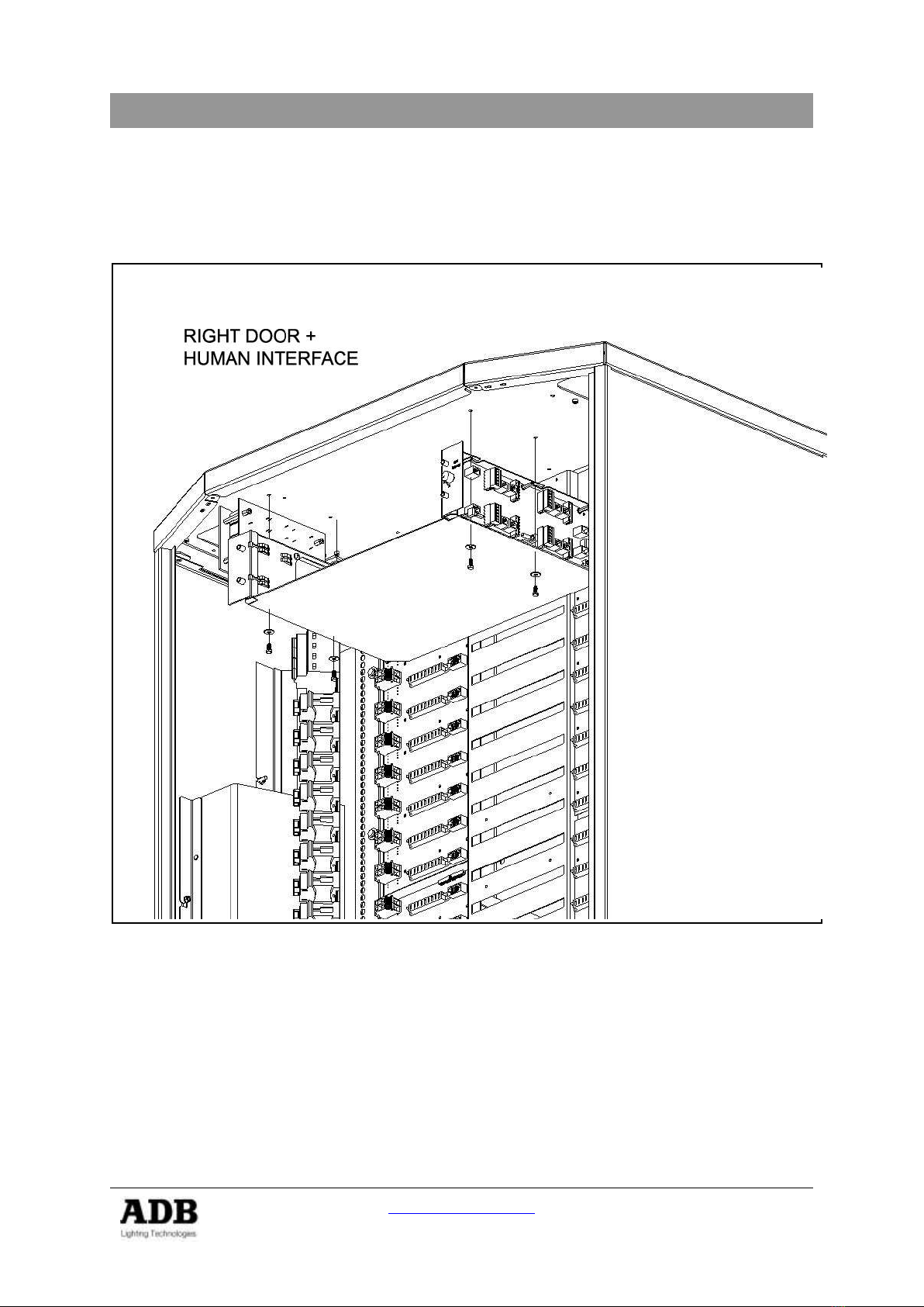
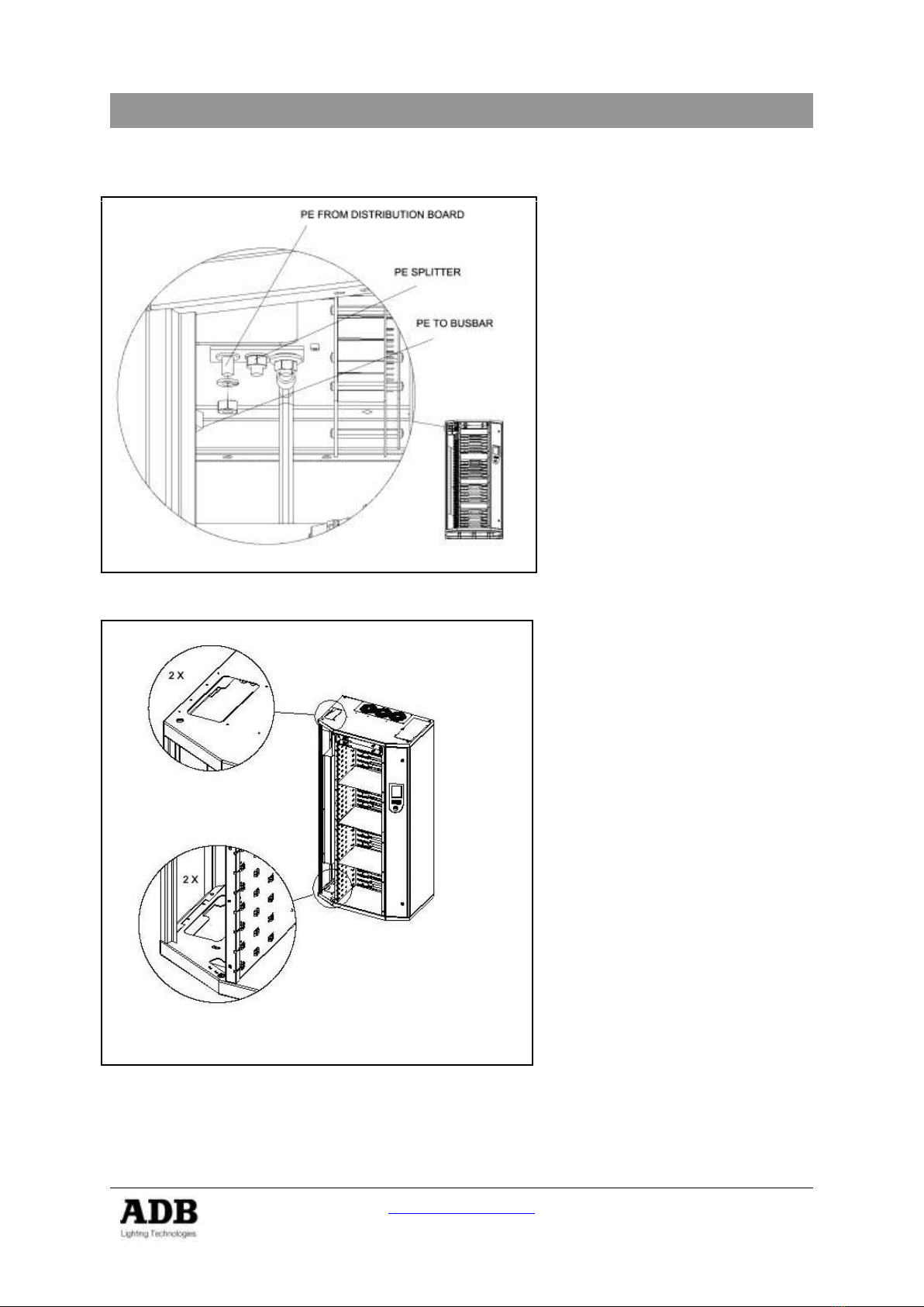
4. CONTRACTOR'S COMPARTMENT –SUPPLY
Front access only is required. Cable entry is possible through bottom and top of the cabinet.
Cover panels for the unused cable entry/ exit apertures are supplied.
In order to gain maximum space to access the
cabinet for installation and maintenance
purposes, remove the two doors, loosen the 16
crosshead screws in the back and 3 left + right
at the bottom and dismount the entire card
cage in one piece.
Mounting the cabinet, first insert the card cage,
enter two dimmer modules to align the rack
and fasten the 16 screws. Put the doors in
place and reconnect the doors earth
connection.
EURODIM TWIN TECH
www.adblighting.com
Installation manual - Page 11
Version 1.2
4.1 Controller Electronics - CPU/ PSU crate
The CPU/ PSU crate is already mounted in our factory. If a removal is required, loosen the 4
screws and remove the complete crate gently. Replace the connected flat cables with
caution.
4.2 Supply voltage
The high voltage/low voltage power transformer MUST ABSOLUTELY provide a three phase
star system with available neutral (3NPE-400), and rated line voltage 380 V to 415 V
between phases and 220 V to 240 V rated voltage between each phase and neutral. See
“Protections” for more details.
The supply cable must have the four current-carrying power conductors (not necessarily the
PE conductor) twisted under the same sleeve, in order to reduce the electrical noise induced
by large dimmed currents.
The neutral conductor must be of equal or larger size than the phase conductors.
See the Appendix to this manual for more details about power supply systems for dimmer
systems.

EURODIM TWIN TECH
www.adblighting.com
Installation manual - Page 12
Version 1.2
4.3 Supply busbar
The three phase connection points are labelled L1 (phase No. 1, phase R), L2 (phase No. 2,
phase S) and L3 (phase No. 3, phase T).
The Neutral is labelled N and the colour code for the Neutral is blue, as per IEC
Recommendation 446.
The Phase and Neutral connection bars have 2 holes of Ø 13 mm, with 22 mm distance
between centres. Connections are suitable for size M 12 bolts and nuts, for connection of up
to four supply conductors. The conductors must be fitted with cable lugs.
EURODIM TWIN TECH
www.adblighting.com
Installation manual - Page 13
Version 1.2
4.3.1 Protected Earth (PE) The Protective Earth (PE) on the
busbar connection is a bolt and
nut, size M10. Colour code:
green/yellow. The equipotential
connection, connecting the metal
frame, is provided at the top of the
supply cabling compartment. This
connection is already wired to the
busbar PE. An additional PE
connection is provided on the
cabinet’s bottom of the supply
compartment. All necessary nuts
and washers are included.
4.4 Connecting power supply cables.
Supply cables can be wired in
parallel, whilst each of these
cables must contain the three
phases and the Neutral under the
same sleeve. This cable must be
protected in the switchboard. The
total size of the conductors must
be chosen depending on the total
power of the dimmers, the utility
factor, the general protection on
the supply side, the voltage drop in
the line and local regulations. We
suggest the use of several cables
placed in parallel, to facilitate the
work of the contractor: the cables
usually have a bending radius of
min. 15 times their external
diameter. Respect an angle of 30
degree to connect the supply cable
in order to achieve necessary
distance between the cables and
busbar. Use the wholes on bottom
and top to connect the cable wraps
for stress relief.

EURODIM TWIN TECH
www.adblighting.com
Installation manual - Page 14
Version 1.2
4.5 Ground and Earth Connections
The sound or video earth should be separated from the dimmer earth. The distance between
the dimmer earth and the others should be as large as possible. Refer to local regulations for
grounding.
Regarding the Protection Earth (PE) local and international rules and regulations apply. If in
doubt about the correct please consult a local approved electrical engineer specialists for
advice in your particular case.

EURODIM TWIN TECH
www.adblighting.com
Installation manual - Page 15
Version 1.2
5. SEQUENTIAL DIAGNOSTICS (Optional)
In case the client has ordered the option:
One Sequential Diagnostics kit must be installed for each dimmer cabinet in the installation.
The sequential diagnostics function is similar in function to the diagnostics already used in
the EURODIM 3. The dimmer channels are examined one after the other (sequential) and
the value is reported either to the local Human Interface or a remote program running the
TTD Management Software.
The communication to a single remote reporting pc is done via the proprietary ADB ADN
protocol based on an Ethernet Network to a Personal Computer with the Windows Operating
System running the TTD Management Software. The Ethernet information is generated by
each EURODIM Twin Tech controller and physically available for each individual controller
on dedicated RJ45 connectors (Two possible per cabinet if double controller options are
used).
The TTD Management Software and the necessary hardware are available as option for the
EURODIM Twin Tech cabinet, which shall be ordered separately installation.
Standard functions include
Presence of Mains and DMX signal
Processor (active) check
Over Temperature
Fan Failure (Information per FAN!)
DMX Control Levels
Local test of a dimmer (steady, flash or chaser)
Automatic self-test of control electronics.
Error messages and all events/parameters are available for display locally on the EURODIM
Twin Tech Human Interface Controller and/or remotely on the TT Dimmer Manager PC
connected via an Ethernet Network. (use of ADN protocol)
Scan Load and the related functions are pre-show
1
test routines providing additional
information on the status of each dimmer, i.e.
Value of the dimmer load (kW)
Deviation from reference load
No load, overload warnings
Short-Circuit
The necessary hardware to perform Sequential Diagnostic measurements is an option and
which shall be installed at the client’s site.
1
Sequential Diagnostics cannot be used during a show, since control is disabled and the dimmers
system runs through a test routine.
EURODIM TWIN TECH
www.adblighting.com
Installation manual - Page 16
Version 1.2
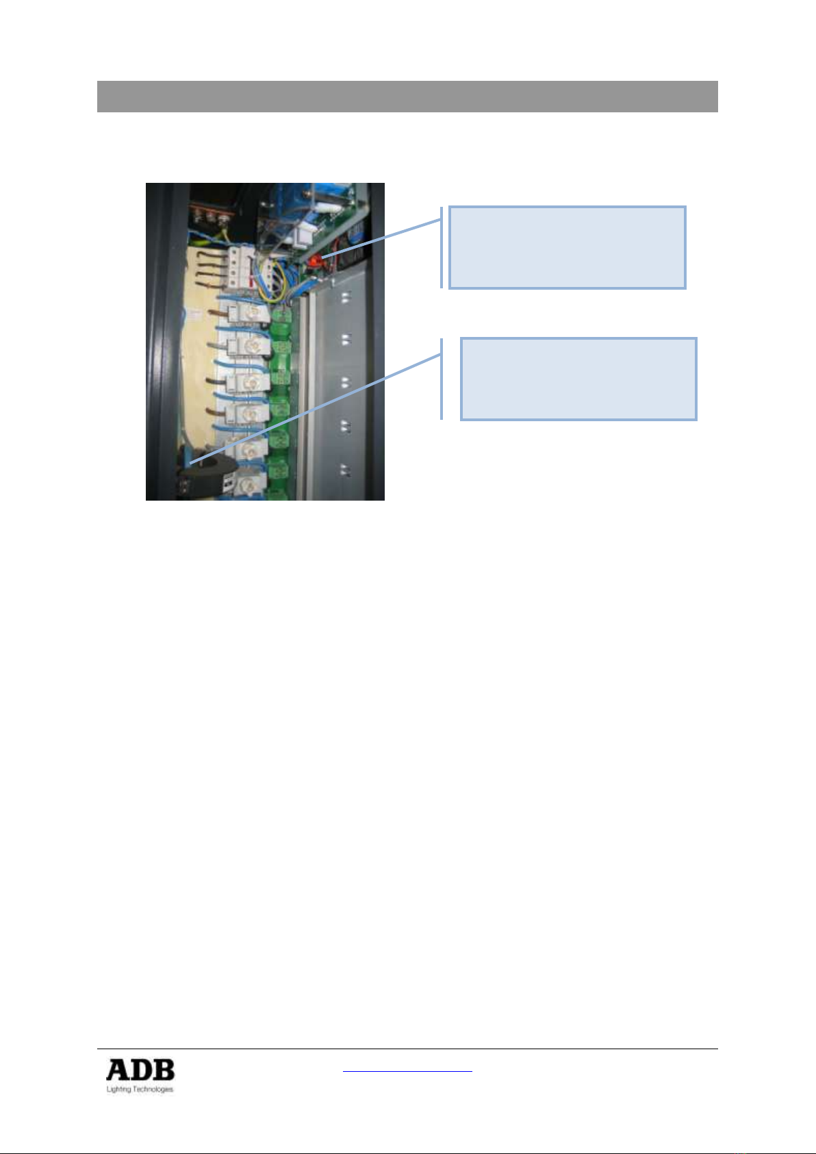
5.1 Hardware installation
Overview of EDTT cabinet - Supply Compartment
All the hardware installations are to be performed in the left hand contractor department. This
is where the EURODIM Twin Tech cabinet receives the power supply. It is advisable to
mount the hardware before you introduce the power supply cables, because there is more
space for the installation left.
The only cable which shall pass through the TI (power coil) is the neutral cable (blue) - the
other supply lines pass on the outside of the TI. The TI coil has a latching mechanics
allowing to open the coil and to pass the (large) neutral cable through it. There is a cable
(approx. 150 cm) with grey and blue wire. This cable is to be brought to the upper right hand
side of the cabinet, where the PCB 3015 is to be mounted.
PCB 3015 for communication
to Processor Unit.
TI –Measuring Coil. The
NEUTRAL (blue) cable from
the cabinet power supply must
pass through.
EURODIM TWIN TECH
www.adblighting.com
Installation manual - Page 17
Version 1.2
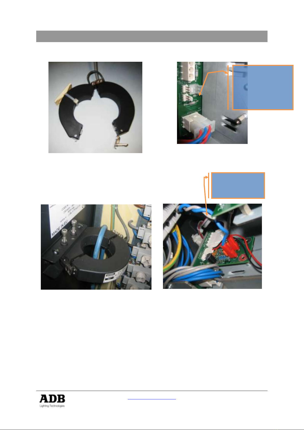
5.2 Mounting Procedure
Figure 1: open TI before mounting
(Cable for connection to PCB 3015)
Detail of Mounting Place for PCB 3015
5.3 Finished installation
Detail of TI with mounting Kit
Detail of PCB 3015 connected
The PCB 3015 is fixed with 2 provided screws to the central controller housing.
PCB 3015
Connector
(the other
connectors remain
as they are for fan
power).
Cables from TI
(Grey/Blue)
EURODIM TWIN TECH
www.adblighting.com
Installation manual - Page 18
Version 1.2
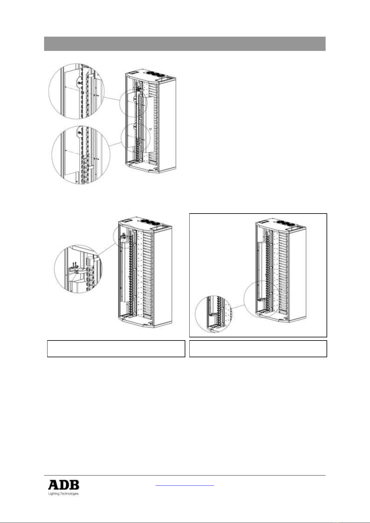
Installation of TI –Measurement device
1.) Remove the Bus-Bar protection (2
Screws).
2.) Install the TI-Holder (long metal
plate) –Direction depends if the
cable entry is from the top or bottom
of cabinet.
3.) Connect Phase and Ground Cable to
the Bus-Bar with suitable screws.
4.) Bring the NEUTRAL (blue) cable
through the TI (the TI can be opened
for easier installation.
5.) Connect the NEUTRAL to the bus
bar.
6.) Place the Bus-Bar protection back in
the cabinet –and attach with the two
screws.
Mounting of the TI for supply cable entry
from the top of the cabinet
Mounting of the TI for supply cable entry
from the bottom of the cabinet
5.4 Software Installation
The black lines are ETHERNET connections between the EURODIM Twin Tech, Switch and
PC running the TTD Management Software. This software must only be installed one time.
At the same time a lighting control desk (which must support ArtNET communications
protocol) may be connected to the ETHERNET Switch. To simplify the image the control
desk has not been included in the drawing. Both the PC running TTD Management Software
and the lighting control desk (e.g. ADB LIBERTY, FREEDOM or MENTOR desks) may
operate simultaneously and there is no influence, since both systems work with different
protocols. Alternatively the control desk may be connected to one of the DMX inputs of the
EURODIM Twin Tech cabinet. (Instead of using ArtNET protocol). The ETHERNET switch is
connected with suitable communication cables (e.g. CAT5) to handle the dimmer information
as well as the ArtNET communication.
Other manuals for EURODIM TWIN TECH
1
Table of contents
Other ADB Lighting Equipment manuals


 SBOL User manual")


