Table of Contents
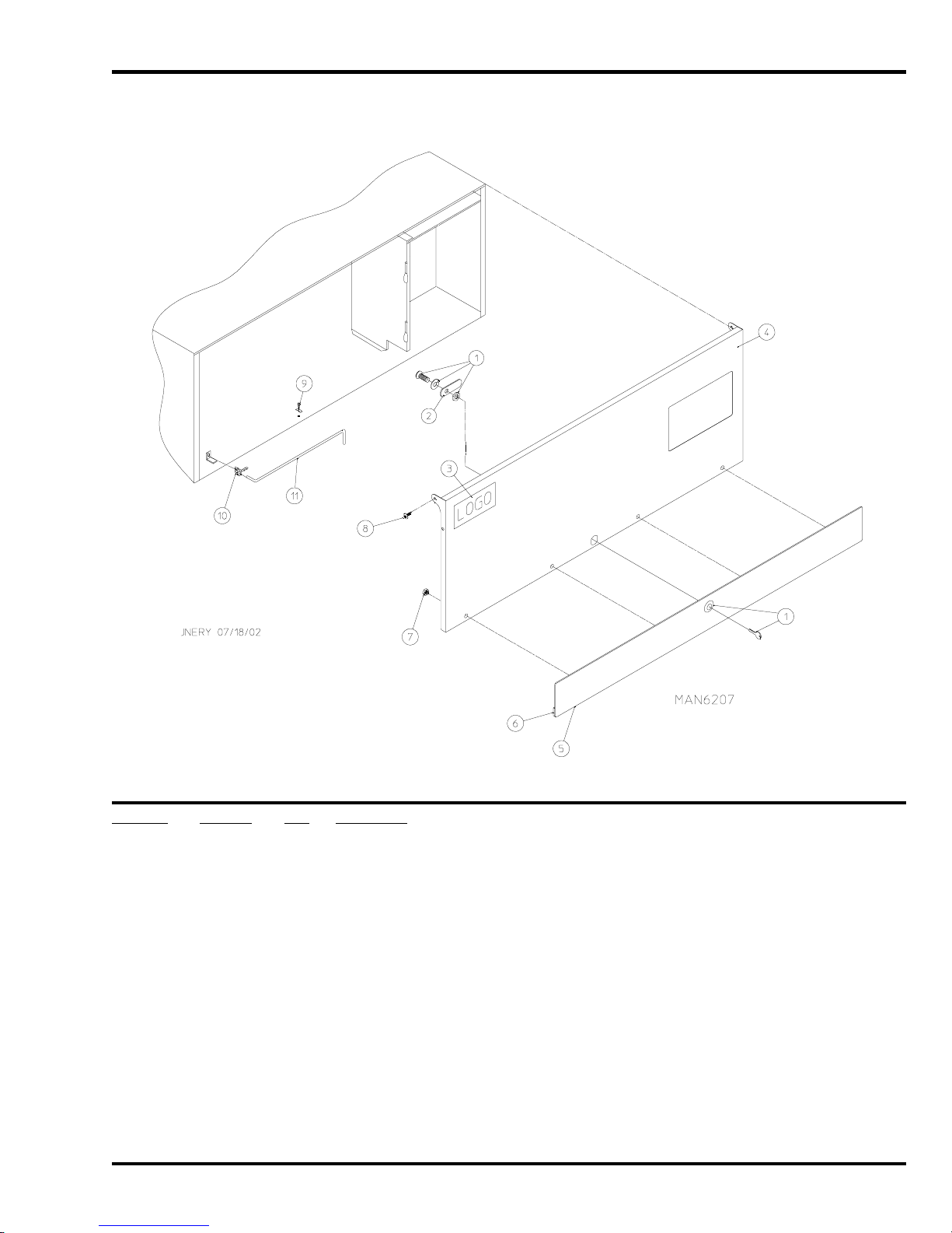
Non-Coin Control Door Assembly for Models Mfd. as of July 1, 2002.......................................................................................... 4
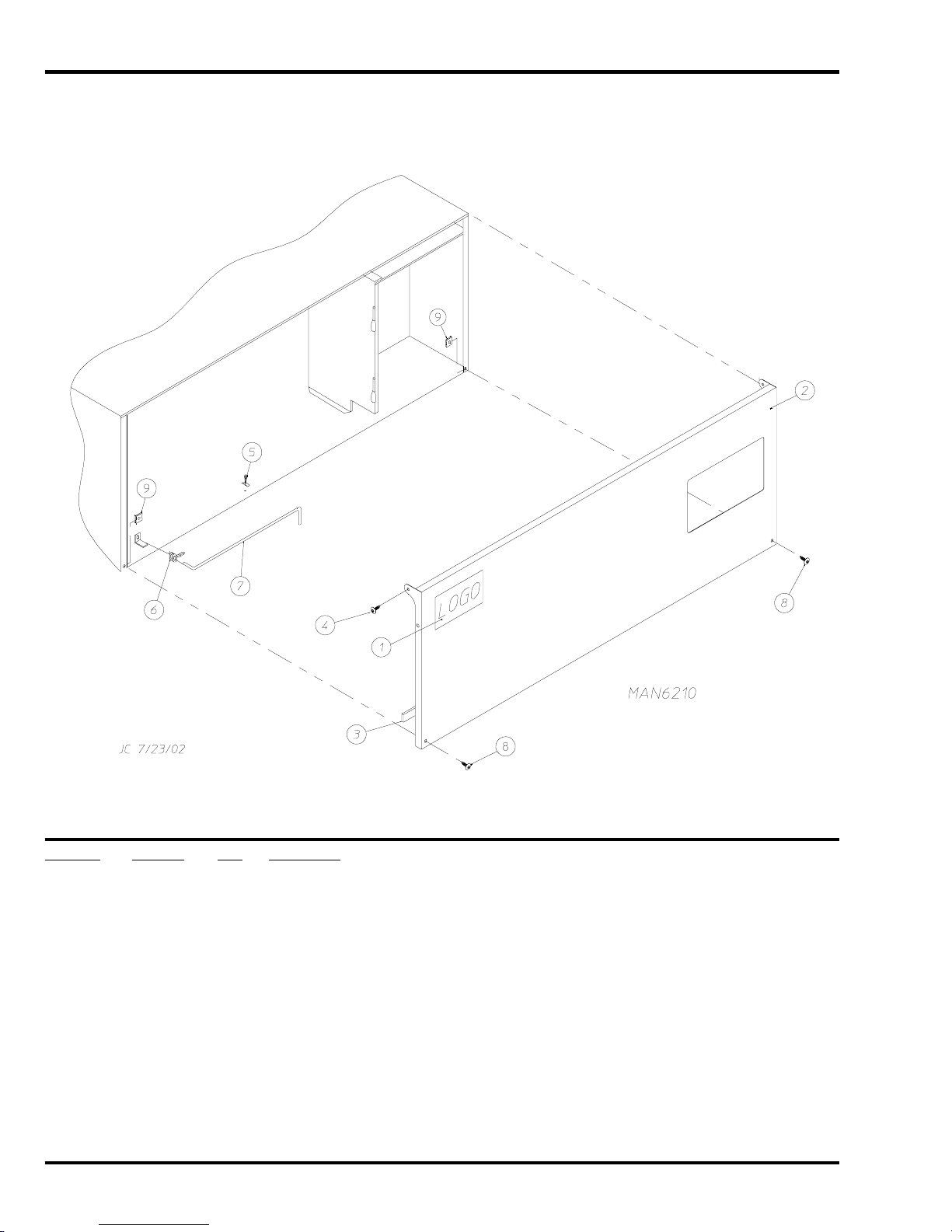
Coin Control Door Assembly for Models Mfd. as of July 1, 2002.................................................................................................. 5
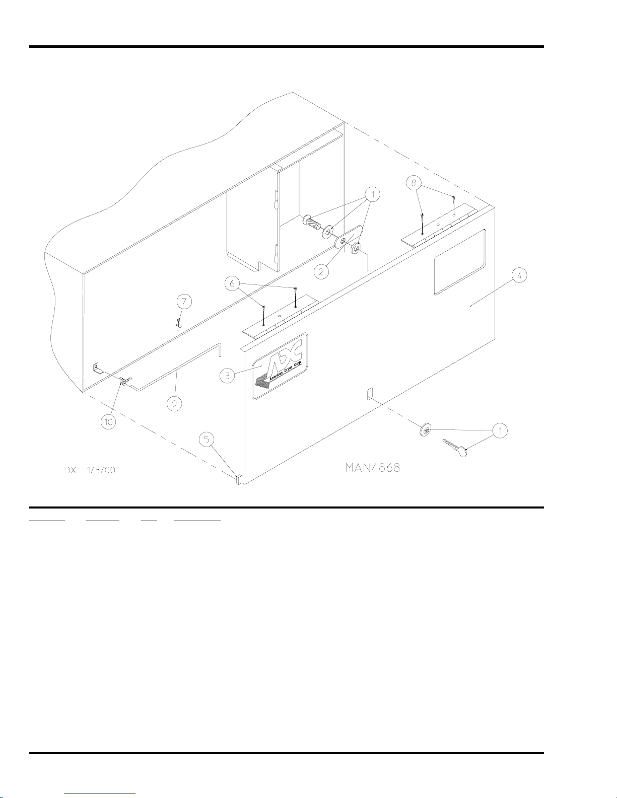
Control Door Assembly for Models Mfd. prior to July 1, 2002....................................................................................................... 6
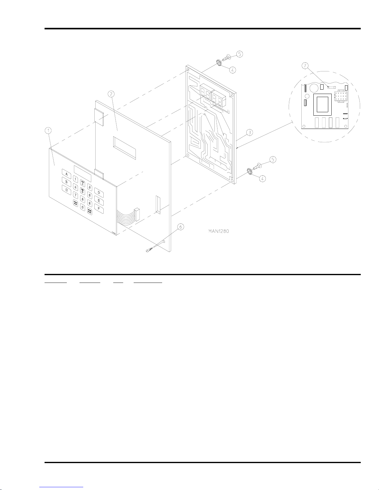
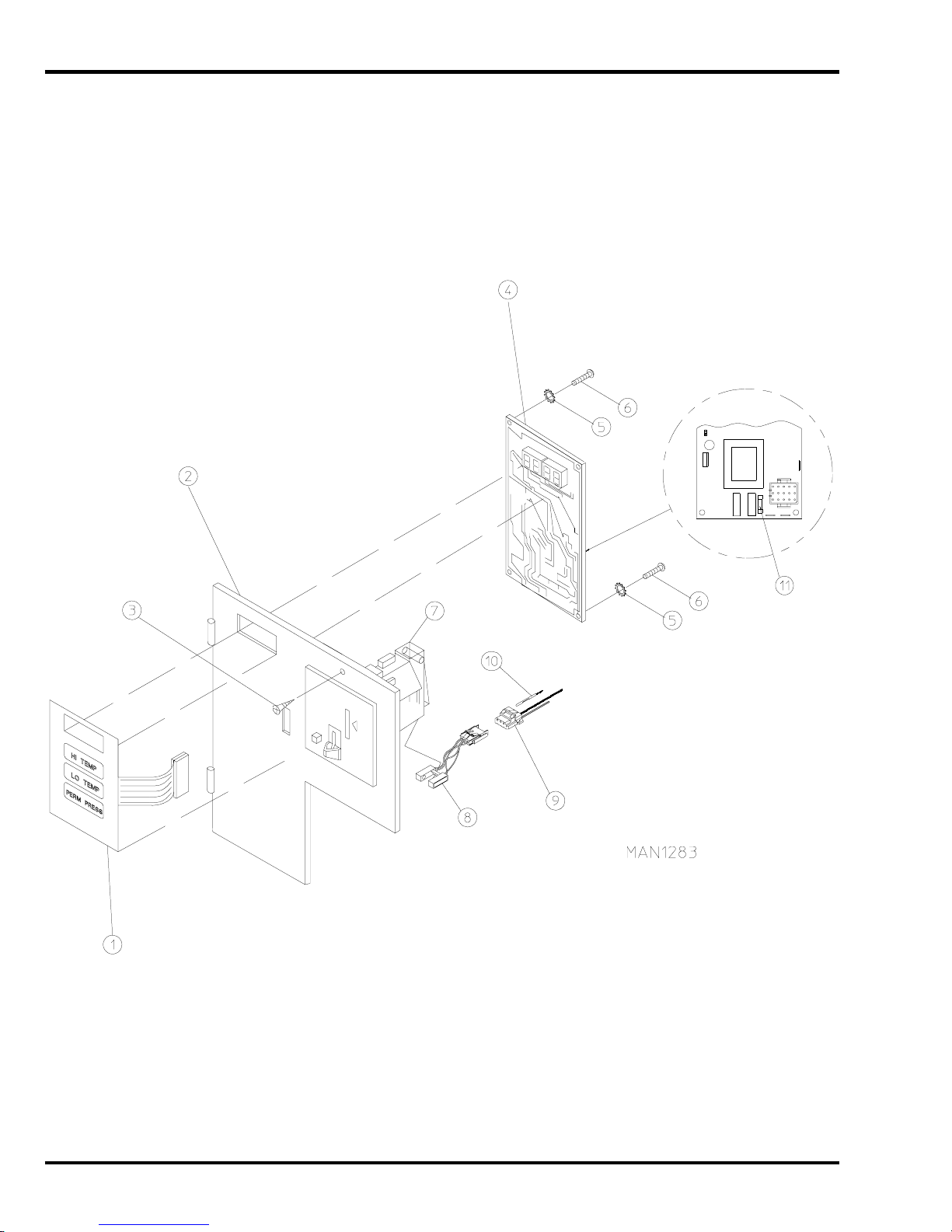
Phase 5 Non-Coin Microprocessor Control Panel Assembly ........................................................................................................ 7
Phase 5 Coin Microprocessor Control Panel Assembly................................................................................................................ 8
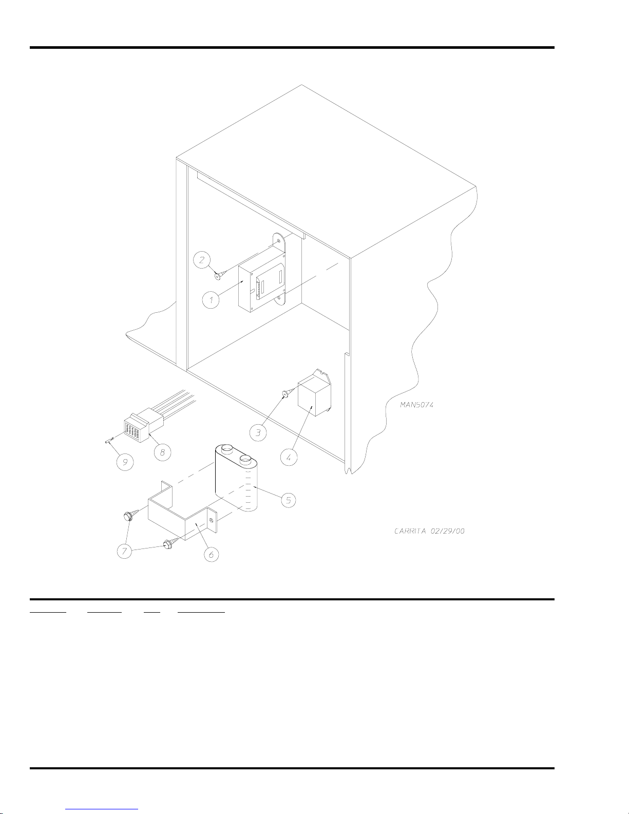
Coin and Non-Coin Control Box Assembly .................................................................................................................................. 10
Dual Timer “Tap Touch” Controls for Models Mfd. as of November 1, 2000 ................................................................................11
Dual Timer Control Panel Assembly for Models Mfd. prior to November 1, 2000 ...................................................................... 12
Non-Microprocessor Coin Meter Control Panel Assembly for Models Mfd. as of January 25, 2002 ......................................... 13
Non-Microprocessor Coin Meter Control Panel Assembly for Models Mfd. prior to January 25, 2002...................................... 14
Coin Vault Assembly..................................................................................................................................................................... 15
Front Panel Assembly for Models Mfd. with Steel Main Door as of July 1, 2002 ....................................................................... 16
Front Panel Assembly for Models Mfd. with Steel Main Door prior to July 1, 2002 .................................................................... 17
Front Panel Assembly for Models Mfd. with Plastic Main Door................................................................................................... 18
Main Door “Steel” Assembly......................................................................................................................................................... 19
Plastic Main Door Assembly......................................................................................................................................................... 20
Main Door Switch Assembly for Models Mfd. with Steel Main Door............................................................................................ 21
Main Door Switch for Models Mfd. with Plastic Main Door.......................................................................................................... 22
Tumbler / Support Assemblies ..................................................................................................................................................... 23
Sensor Bracket Assemblies for Models Mfd. as of July 1, 2002 ................................................................................................. 24
Sensor Bracket Assemblies for Models Mfd. prior to July 1, 2002.............................................................................................. 26
Drop Lint Door Assembly for Models Mfd. as of July 1, 2002 ..................................................................................................... 28
Lint Trap Assembly for Models Mfd. as of July 1, 2002............................................................................................................... 29
Lint Drawer / Lint Drawer Switch Assemblies for Models Mfd. between August 10, 2000 and July 1, 2002 ............................. 30
Lint Drawer / Lint Drawer Switch Assemblies for Models Mfd. prior to August 10, 2000............................................................ 31
Tumbler Bearing Assembly for Models Mfd. as of August 11, 2000............................................................................................ 32
Tumbler Bearing Assembly for Models Mfd. prior to August 11, 2000 ........................................................................................ 34
Idler Bearing Assembly ................................................................................................................................................................ 36
Gas Burner Assembly for Models Mfd. as of May 20, 2000 ........................................................................................................ 37
Direct Spark Ignition Burner Assembly for Models Mfd. prior to May 20, 2000 .......................................................................... 38
Sail Switch / Hi-Limit Assemblies................................................................................................................................................. 39
Non-Reversing Motor Mount Assembly ....................................................................................................................................... 40
Reversing T.E.F.C. Motor Mount Assembly.................................................................................................................................. 42
Electric Oven Assembly ............................................................................................................................................................... 44
Single-Phase (1ø) Motor, Electric Relay Panel Assembly........................................................................................................... 46
3-Phase (3ø) Motor, Electric Relay Panel Assembly................................................................................................................... 47
460-480 VAC 3-Phase (3ø) Motor, Electric Relay Panel Assembly ............................................................................................ 48
Reversing Electric Relay Panel Assembly ................................................................................................................................... 49
460-480 VAC Reversing Electric Relay Panel Assembly ............................................................................................................ 50
Steam Coil / Air-Operated Steam Damper Assembly .................................................................................................................. 51
Steam Coil / Mechanical Steam Damper Assembly .................................................................................................................... 52
Outer Top / Back Guard Assemblies............................................................................................................................................ 53
Microprocessor Coin Acceptors Listing ....................................................................................................................................... 54
Coin Meter Replacement Parts .................................................................................................................................................... 55
Electrical Oven Component Application Chart ............................................................................................................................ 56
Additional Parts Available............................................................................................................................................................. 57