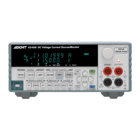
ADCMT 12702A User manual

©2009 ADC CORPORATION First printing March 31, 2009
All rights reserved. Printed in Japan
12702A/B
Resistivity Chamber
OPERATION MANUAL
Manual Number FOE-00000047A00


C-1*
12702A/B Resistivity Chamber Operation Manual
Table of Contents
1. Introduction..................................................................................................1-1
1.1 Product Overview.........................................................................................................................1-1
1.2 Before Using the Product .............................................................................................................1-1
2. Panel Descriptions........................................................................................2-1
2.1 Front Panel....................................................................................................................................2-1
2.2 Electrodes .....................................................................................................................................2-3
2.3 Volume and Surface Resistivity Measurements............................................................................2-4
2.4 How to Calculate Volume and Surface Resistivities.....................................................................2-5
2.5 Pressure to Electrode ....................................................................................................................2-7
2.6 Cover ............................................................................................................................................2-7
2.7 Sample Thickness Measurement ..................................................................................................2-7
2.8 Internal Connection ......................................................................................................................2-7
3. Measurement Method ..................................................................................3-1
3.1 Connecting to the Measuring Instruments....................................................................................3-1
3.2 Measuring Volume and Surface Resistivities ...............................................................................3-4
4. Storage..........................................................................................................4-1
5. Specifications...............................................................................................5-1


F-1*
12702A/B Resistivity Chamber Operation Manual
List of Illustrations
No. Title Page
2-1 Front Panel ………………………………………………………………... 2-1
2-2 Electrodes …………………………………………………...…………….. 2-3
2-3 Electrode Diameters ………………………………………………………. 2-6
2-4 12702A/B Internal Connection …………………………………………… 2-7
2-5 Internal Connection for Volume Resistivity Measurement ………………. 2-8
2-6 Internal Connection for Surface Resistivity Measurement ………………. 2-8
3-1 Dial Gauge Alignment …………………………………………….………. 3-5


T-1*
12702A/B Resistivity Chamber Operation Manual
List of Tables
No. Title Page
2-1 LO-GUARD Switch SHORT/OPEN Switching …………………………… 2-1
3-1 Connectable Measuring Instruments and Necessary Cables ………………. 3-1


1-1
12702A/B Resistivity Chamber Operation Manual
1.1 Product Overview
1. Introduction
1.1 Product Overview
The 12702A/B resistivity chamber is a shield box containing electrodes. It is used to measure
the volume resistivity and surface resistivity of sheet, filmy and platy samples together with a
voltage source such as the 8252 or 8240 digital electrometer, the 8340A digital ultra-high re-
sistance/micro current meter, or the 6161 DC current voltage source/monitor.
Features:
zThe pressure to the electrodes can be varied according to the sample used, allowing the
sample to be fixed firmly and reducing the measurement error.
zThe electrodes in the shielded box can be connected to a measuring instrument easily
with the connectors.
zVolume and surface resistivity measurements can be switched by pressing the button
switch.
zHigh-voltage application turns on and off according to opening and closing of the cover
of the shielded box for safety operation.
zThere are two types of resistivity chambers with electrodes of different size.
The 12702A complies with JIS-K6911, and the 12702B with JIS-K6723.
zThe thickness of a sample necessary for volume resistivity calculation can be measured
by using the dial gauge.
zA large sample can be measured without being cut.
1.2 Before Using the Product
When receiving the 12702A/B, inspect it for transport damage.
If there is any damage or defect, please contact ADC Corporation or your sales representative.
Our address and phone number are listed at the end of this manual.


2.
P
2.1 F
1
2
P
anel De
s
ront Pan
e
1
.INPUT
A
A conne
c
INPUT s
u
The cent
e
2
.INPUT
B
A conne
c
INPUT s
u
The cent
e
s
criptio
n
e
l
A
: Triaxial c
o
c
tor to conn
u
ch as the 8
3
e
r contact is
c
B
: M-type co
n
c
tor to conn
e
u
ch as the T
R
e
r contact is
c
n
s
Figur
e
o
nnecto
r
ect with a
m
3
40A, 8252
o
c
onnected t
o
n
necto
r
e
ct with a
m
R
8611A, T
R
c
onnected t
o
12702A/
B
e
2-1 Fron
t
m
easuring i
n
o
r 8240.
o
the main el
e
m
easuring in
s
R
8601, TR86
4
o
the main el
e
B
Resistivit
y
t
Panel
n
strument h
a
e
ctrode.
s
trument ha
v
4
1, TR8411
e
ctrode.
y
Chamber
a
ving a tria
x
v
ing an M-t
y
or TR8401.
Operation
M
2.1 Fr
o
x
ial connect
o
y
pe connect
o
2-1
M
anual
o
nt Panel
o
r on the
o
r on the

2-2
12702A/B Resistivity Chamber Operation Manual
2.1 Front Panel
3. LO-GUARD switch
A button switch to switch SHORT and OPEN between the inner and outer shields of the
INPUTA (triaxial connector) depending on the connected instrument.
Refer to the following table.
Table 2-1 LO-GUARD Switch SHORT/OPEN Switching
Instrument 8340A 8240 8252 TR8652 TR8601 TR8411
LO-GUARD switch
SHORT/OPEN OPEN OPEN OPEN OPEN SHORT SHORT
4. V SOURCE terminal
A connector to connect with a voltage output terminal such as the V SOURCE of the
8340A and the OUTPUT of the 8252 or 6161.
Both HI and LO connections are switched by the RESISTIVITY switch. The HI connection
is disconnected when the cover is opened, and is connected to the guard electrode or op-
posed electrode when it is closed.
5. RESISTIVITY switch
A button switch to switch volume resistivity measurement (VOLUME) and surface resis-
tivity measurement (SURFACE).
Selecting VOLUME will connect the HI of the V SOURCE terminal to the opposed elec-
trode and the LO to the guard electrode.
Selecting SURFACE will connect the HI to the guard electrode and the LO to the opposed
electrode.

2.2
E
1
2
3
4
5
E
lectrode
s
1
.Main ele
c
Connects
measure
sample u
s
2
.Guard el
e
Connects
ducing t
h
Connects
come a
h
and this
e
3
.Opposed
Connects
b
ecome
a
and this
e
Connects
ducing t
h
flowing i
n
4
.Dial
Used to
m
to the ele
5
.Dial Gau
g
Used to
m
s
c
trode
with the I
N
insulation r
e
s
ed, allowin
g
e
ctrode
with the L
O
h
e measurem
e
with the H
I
h
igh-voltage
e
lectrode.
electrode
with the
H
a
high-volta
g
e
lectrode.
with the L
O
h
e measure
m
n
a sample.
m
ove up an
d
ctrodes to
m
g
e
m
easure the
t
Figu
r
N
PUT A and
e
sistance, a
n
g
the sample
O
of the V
S
e
nt error by
I
of the V S
O
application
H
I of the V
S
g
e applicatio
n
O
of the V
S
m
ent error b
d
down the
m
m
ake a sampl
e
t
hickness of
12702A/
B
r
e 2-2 Elec
B connecto
r
n
d pressure
t
to be fixed
f
S
OURCE te
r
canceling c
u
O
URCE ter
m
electrode.
V
S
OURCE te
r
n
electrode.
V
S
OURCE te
r
y canceling
m
ain electro
d
e
and the ele
a sample ne
c
B
Resistivit
y
trodes
r
s on the fro
n
t
o be applie
d
f
irmly.
r
minal in vo
l
u
rrent flowin
m
inal in surf
a
V
oltage is ap
p
r
minal in v
o
V
oltage is a
p
r
minal in su
r
current for
d
e and the g
u
ctrodes stic
k
c
essary for
v
y
Chamber
n
t panel. Th
i
d
can be va
r
l
ume resisti
v
g on the sur
f
a
ce resistivit
y
p
lied betwe
e
o
lume resist
i
p
plied betwe
e
r
face resisti
v
volume res
u
ard electro
d
k
fast to eac
h
v
olume resist
Operation
M
2.2
E
i
s electrode
i
r
ied accordi
n
v
ity measure
f
ace of a sa
m
y
measurem
e
e
n the main
i
vity measu
r
e
n the main
v
ity measure
istivity me
a
d
e and appl
y
h
othe
r
.
t
ivity calcul
a
2-3
M
anual
E
lectrodes
i
s used to
n
g to the
ment,
r
e-
m
ple.
e
nt to be-
electrode
r
ement to
electrode
ment,
r
e-
a
surement
y
pressure
a
tion.

2-4
12702A/B Resistivity Chamber Operation Manual
2.3 Volume and Surface Resistivity Measurements
2.3 Volume and Surface Resistivity Measurements
The 12702A/B switches volume resistivity measurement and surface resistivity measurement
with the RESISTIVITY switch on the front panel.
VOLUME: Measures volume resistivity
SURFACE: Measures surface resistivity

2-5
12702A/B Resistivity Chamber Operation Manual
2.4 How to Calculate Volume and Surface Resistivities
2.4 How to Calculate Volume and Surface Resistivities
Formulas to calculate volume and surface resistivities are described below:
Volume resistivity:
ρv
Rv ------- (1)
Surface resistivity:
ρs
Rs ------- (2)
The electrode diameters of the 12702A/B are as follows: (See Figure 2-3.)
12702A JIS-K6911-compliant
12702B JIS-K6723-compliant
The following formulas are obtained by substituting these values for formulas (1) and (2).
12702A
Volume resistivity: ρv 19.63
[Ω cm] ------- (3)
Surface resistivity: ρs 18.84 Rs [Ω] ------- (4)
12702B
Volume resistivity: ρv 38.47
[Ω cm] -------- (5)
Surface resistivity: ρs 25.12 Rs [Ω] -------- (6)
By substituting measured values for formulas (3) to (6), the volume resistivity and the surface
resistivity can be obtained.
ρ
v : volume resistivity [Ω cm]
ρ
s : surface resistivity [Ω]
Rv : volume resistance [Ω] (Measured value)
Rs : surface resistance [Ω] (Measured value)
π: circumference ratio=3.14
t : sample thickness [cm]
D : guard electrode inner diameter [cm]
d : main electrode diameter [cm]
Main electrode diameter = 50 mm dia.
Guard electrode inner diameter = 70 mm dia.
Main electrode diameter = 70 mm dia.
Guard electrode inner diameter = 90 mm dia.

2-6
12702
A
2.4 H
o
A
/B Resisti
v
o
w to Calcula
t
v
ity Chamb
e
t
e Volume a
n
e
r Operatio
n
n
d Surface R
e
Figur
e
n
Manual
e
sistivities
e
2-3 Elect
r
Main electr
o
Guard el
e
Sampl
e
Opp
o
r
ode Diamet
e
o
de
e
ctrode
e
o
sed electrod
e
e
rs
e

2.5 P
P
a
c
c
2.6
C
T
c
B
2.7 S
T
v
t
h
F
2.8 I
n
F
F
F
ressure t
o
P
ressure to b
a
pplying co
n
c
itance
b
etw
e
c
apacitance
f
C
over
T
he cover o
f
c
annot be ap
p
B
e sure to cl
o
ample T
h
T
he thicknes
v
olume resis
t
h
e sample.
F
or how to c
a
n
ternal C
F
igure 2-4 s
h
F
igure 2-5 s
h
F
igure 2-6 s
h
o
Electro
d
e applied to
n
stant pressu
r
e
en electrod
e
f
rom changi
n
f
the 12702
A
p
lied to the
e
o
se the cove
r
h
ickness
M
s of a samp
l
t
ivity. The 1
a
lculate the
v
onnectio
n
h
ows the int
e
h
ows the int
e
h
ows the int
e
d
e
the main el
e
r
e, the clear
a
e
s are kept
c
n
g due to en
v
A
/B adopts
a
e
lectrodes.
O
r
during me
a
M
easure
m
l
e is require
d
2702A/B is
v
olume resis
n
e
rnal connec
t
e
rnal connec
t
e
rnal connec
t
Figure 2-4
12702A/
B
e
ctrode can
b
a
nce betwee
c
onstant dur
i
v
ironmental
v
a
safety shie
l
O
nly when it
i
a
suremen
t
.
m
ent
d
for measu
r
equipped w
i
tivit
y
, refer
t
t
ion of the 1
2
t
ion for volu
m
t
ion for surf
a
12702A/B
B
Resistivit
y
b
e varied to
m
n the electr
o
i
ng measure
v
ibrations, p
l
d design.
W
i
s closed, v
o
r
ing the vol
u
i
th the dial
g
t
o Chapter 3
.
2
702A/B.
m
e resistivit
y
a
ce resistivit
y
Internal Co
n
Elect
r
y
Chamber
2.5
m
ake it stic
k
o
de and the
s
ment. In ad
d
roviding sta
b
W
hen the co
v
o
ltage can be
u
me resistan
c
g
auge to me
a
.
2.
y
measurem
e
y
measurem
e
n
nection
r
odes
Chassis
Operation
M
Pressure to
k
fast to a sa
s
ample and
t
d
ition, it pr
e
b
le measure
d
v
er is opene
d
applied.
c
e and calcu
l
a
sure the thi
c
e
nt.
e
nt.
2-7
M
anual
Electrode
m
ple. By
t
he capa-
vents the
d
values.
d
, voltage
l
ating the
c
kness of

2-8
12702
A
2.8 Int
e
A
/B Resisti
v
e
rnal Conne
c
F
F
v
ity Chamb
e
c
tion
F
igure 2-5
F
igure 2-6
e
r Operatio
n
Internal Co
n
Internal Co
n
n
Manual
n
nection for
n
nection for
V
olume Res
i
Surface Res
i
i
stivity Mea
s
i
stivity Mea
s
s
uremen
t
s
uremen
t

3-1
12702A/B Resistivity Chamber Operation Manual
3.1 Connecting to the Measuring Instruments
3. Measurement Method
3.1 Connecting to the Measuring Instruments
This section describes the procedure of connecting the 12702A/B to measuring instruments.
For the details of each instrument, refer to the operation manual.
The following table shows connectable instruments and necessary cables.
Table 3-1 Connectable Measuring Instruments and Necessary Cables
8340A 8240 8252 TR8652 TR8601 TR8411 6161
TRIAX-TRIAX cable
(A01009) 999
M-type-M-type cable
9* 9* 9*
High-power output cable
9*
BNC-alligator clip cable
(MI-03) 9*
Output cable
(A01044) 9*
Banana adapter
(A08531) 9*
Banana-banana cable
(A01240) 9
9
* Supplied accessory
(1) Connecting with the 8340A
a) Connect the GND, GUARD and LO terminals on the input section of the 8340A by us-
ing a short bar.
b) Connect the INPUT terminal of the 8340A to the INPUT A terminal of the 12702A/B by
using the TRIAX-TRIAX cable (A01009).
c) Connect the V SOURCE terminal of the 8340A to the V SOURCE HI terminal of the
12702A/B by using the banana-banana cable (A01240).
d) Set the LO-GUARD switch of the 12702A/B to OPEN.
The 8340Aoutputs applied voltage of maximum 1000 V. Perform measurement with
great care.
CAUTION

3-2
12702A/B Resistivity Chamber Operation Manual
3.1 Connecting to the Measuring Instruments
(2) Connecting with the 8240
a) Connect the INPUT terminal of the 8240 to the INPUT terminal of the 12702A/B by
using the TRIAX-TRIAX cable (A01009).
b) Connect a voltage source such as the 6161 to the V SOURCE HI and LO terminals of
the 12702A/B by using the banana-banana cable (A01240). (Be sure to connect to both
the HI and LO terminals.)
c) Set the D GUARD switch of the 8240 to ON, and the LO-GUARD switch of the
12702A/B to OPEN.
The maximum output voltage will be 1100 V approximately when the 6161 is used.
Perform measurement with great care.
(3) Connecting with the TR8652
a) Connect the INPUT terminal of the TR8652 to the INPUTAterminal of the 12702A/B
by using the TRIAX-TRIAX cable (A01009).
b) Connect the V SOURCE terminal of the TR8652 to the V SOURCE terminal of the
12702A/B by using the BNC-alligator clip cable (MI-03).
c) Set the SHIELD DRIVE switch of the TR8652 to ON, and the LO-GUARD switch of
the 12702A/B to OPEN.
(4) Connecting with the TR8601
a) Connect the INPUT terminal of the TR8601 to the INPUT B terminal of the 12702A/B
by using the supplied M-type-M-type cable.
b) Connect the HIGH VOLTAGE terminal of the TR8601 to the V SOURCE HI and LO
terminals of the 12702A/B by using the supplied connection cable.
c) Set the LO-GUARD switch of the 12702A/B to SHORT.
The HIGH VOLTAGE connector of the TR8601 outputs applied voltage of maxi-
mum 1000 V. Perform measurement with great care.
CAUTION
CAUTION
This manual suits for next models
1
Table of contents
Other ADCMT Measuring Instrument manuals
Popular Measuring Instrument manuals by other brands

Huvitz
Huvitz HLM-9000 Service manual
Endress+Hauser
Endress+Hauser Proline Prowirl 72 operating instructions

Akai
Akai 1700 Service manual

Reichert
Reichert Tono-Pen AVIA Vet Quick reference guide

BEKA
BEKA BA304SG quick start guide

PCB Piezotronics
PCB Piezotronics IMI SENSORS 048M47 Installation and operating manual
Fluke
Fluke i800 instruction sheet
Siemens
Siemens SITRANS FX330 Additional operating instructions
KYORITSU
KYORITSU KEW 2413R instruction manual
Camille Bauer
Camille Bauer SINEAX AM1000 Device handbook
Agilent Technologies
Agilent Technologies J2126A Quick reference guide

Gespasa
Gespasa MGE-110 instruction manual
