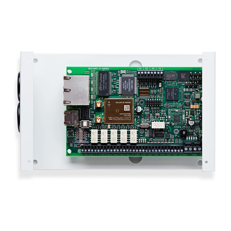
AddSecure Edge VS5010 User manual

PDK-13010-v.6.0 Edge VS5010 and VS5051 User manual
Edge VS5010
and VS5051
User Manual

page 2 PDK-13010-v.6.0 Edge VS5010 and VS5051 User manual
Table of Contents
1 About this manual...................................................................................3
2 Target group............................................................................................3
3 Presentation of the terminals .................................................................3
3.1 AddSecure Connect .........................................................................3
4 Before you start ......................................................................................4
5 Package contents ....................................................................................4
5.1 VS5010.............................................................................................4
5.2 VS5051.............................................................................................4
6 Board configuration ................................................................................5
7 Installation ..............................................................................................6
7.1 Prerequisites....................................................................................6
7.2 Installing the VS5010 terminal ........................................................6
7.2.1 Procedure..............................................................................6
7.3 Installing the VS5051 terminal ........................................................6
7.3.1 Procedure..............................................................................6
7.4 Connecting power ...........................................................................7
7.5 Fitting backup batteries for VS5051 ................................................7
7.6 Connecting voice panels and alarm transmitters............................7
7.7 Connecting the terminal..................................................................7
7.7.1 Power Outputs ......................................................................7
7.8 Powering up the terminal................................................................8
8 Configuring the terminal.........................................................................8
8.1 Checking signal strength..................................................................8
9 Configuration of the voice panels ...........................................................9
10 Commissioning test.................................................................................9
11 Maintenance routine ............................................................................10
11.1 Periodic check of alarm .................................................................10
11.2 Maintaining data ...........................................................................10
11.3 Confirm current status ..................................................................10
11.4 Periodic battery check...................................................................10
11.5 Perform full test and confirmation of alarms................................10
12 Specifications ........................................................................................11
13 Safety ....................................................................................................12
14 Conformance.........................................................................................13
15 Contact..................................................................................................13
15.1
Installation and Service Support
......................................................13
15.2 Sales enquiries...............................................................................13
16
Disclaimer
..............................................................................................13
17
Copyright
...............................................................................................14

PDK-13010-v.6.0 Edge VS5010 and VS5051 User manual page 3
1About this manual
This manual provides a guide to the installation and maintenance of the
VS5010 and Edge VS5051 terminals.
2Target group
This manual is intended to provide assistance to engineers installing and
maintaining the Edge VS5010 or Edge VS5051 terminals at customer sites.
3Presentation of the terminals
Edge terminals, based on the successful range of AoIP Alarm over IP (AoIP)
terminals from AddSecure, offer a new concept in AoIP, providing cost
effective VoIP/AoIP for alarm systems. Both the Edge VS5010 and the Edge
VS5051 are based on the Edge VS5000 motherboard. This motherboard is a
fully equipped circuit board designed to fulfill the task of a Grade 4 Secured
Premises Transmitter (SPT) and meets all relevant standards for EN
compliance in intercom and elevator systems.
The two products based on the VS5000 motherboard are as follows:
Polling and alarm transmission to the alarm receiving centre (ARC) are
performed using 2G/3G/4G, Ethernet or Wi-Fi communications via the
AddSecure Connect platform.
3.1 AddSecure Connect
AddSecure Connect is a cloud-based platform that uses a secure private
LINK network via the on-board eSIM and does not require the installer to
add a SIM card. It provides secure and controlled alarm transmission for
fire, intruder, elevator, technical and other alarms. The platform simplifies
setting up terminals and complying with regulations for the installer, the
customer and alarm receiving centres.
Edge terminals are intelligently provisioned through AddSecure Connect.
AddSecure Connect is perfect for every situation where monitored
communication between a site and the ARC of choice is required, as well as
when there is a need for controlled remote access to an external device.
Add Secure Connect has many features, amongst other, the following:
Easy to switch ARC’s when situation, alarm mix, or environment
changes.
Remote access for installers (analysis and setup) to save cost and time.
Different alarms routed to separate ARC’s for flexible requirements
management.
One alarm routed to multiple ARCs
Variant
Application
VS5010
Is supplied without an enclosure and is intended to be installed in
existing enclosures of intercom and elevator applications.
VS5051
Is supplied in a metal enclosure with 20Hr battery backup for use
in elevator applications.

page 4 PDK-13010-v.6.0 Edge VS5010 and VS5051 User manual
AddSecure Connect also includes the AddView web portal which allows
both customers and installers to monitor different installations and to set
up notification services.
AddSecure Connect is only available when the customer or you, as their
installer, or their ARC, have signed up for a subscription with AddSecure
that defines the chosen service at the agreed subscription grade. For
elevator alarms, AddSecure the grade is set at EU – Grade 2. A connection
to one selected ARC is included in the basic subscription. Additional ARCs
are optional.
As an installer, you may already be aware that you can analyse and setup an
installation remotely over AddSecure Connect. You can read more about
AddSecure Connect on www.addsecure.com.
4Before you start
Ensure that a subscription to AddSecure Connect exists for this terminal
before starting the installation. If you or the customer don't already have
one, please contact AddSecure.
5Package contents
5.1 VS5010
VS5000 PCBA board.
4 x screws and plugs for fixing the housing to a flat surface.
4 x self-tapping metal sheeting screws.
4 x board-to-board standoffs, 30 mm height.
T-bar cellular antenna.
This User Manual.
Ethernet cable.
Cable ties.
5.2 VS5051
VS5000 PCBA board (in enclosure).
H51 metal enclosure.
3000mAH 7.2V NiMH battery (in enclosure).
4 x screws and plugs for fixing the housing to a flat surface.
4 x self-tapping metal sheeting screws.
Magnetic cellular antenna.
This User Manual.
Cable ties.

PDK-13010-v.6.0 Edge VS5010 and VS5051 User manual page 5
6Board configuration
①
Ethernet 1
⑨
Power out: Vout3 (Call Connect)
②
Ethernet 2
⑩
Power out: Vout2 (Buzzer)
③
LEDs
⑪
Power out: Vout1 (Emergency Light)
BT = Not in use
⑫
DC power in
PNL = Panel LED
⑬
Expansion port
PWR = Power LED
⑭
TTL serial port
CEL = Cellular LED
⑮
Pin inputs (4)
ETH = Ethernet LED
⑯
RS232 port
SYS = System LED
⑰
Case Tamper input
④
Cellular diversity antenna port (RX only)
⑱
PSU sense
⑤
SIM card slot
⑲
Outputs (3)
⑥
Primary cellular antenna port (TX/RX)
⑳
RS485 port
⑦
Test Button (Signal Strength)
Dial capture port
⑧
USB port (diagnostics)
Battery port

page 6 PDK-13010-v.6.0 Edge VS5010 and VS5051 User manual
7Installation
7.1 Prerequisites
Before starting this procedure, make sure that all the items listed under
section 5, “Package Contents” are present and correct.
The main unit may only be installed in a locked elevator shaft where only
authorized elevator engineers have access.
Make sure there is enough space to open the main unit cover once the unit
is fixed in place.
7.2 Installing the VS5010 terminal
This procedure covers the installation of the VS5000 circuit board inside an
approved alarm panel or cabinet enclosure and the connection of the
relevant alarm devices. The enclosure should be positioned in order to
ensure a good 4G signal and connection.
7.2.1 Procedure
Step Action
1 Position and affix the VS5000 terminal in the enclosure using the
fixing kits supplied.
2 Connect cables from the alarm panels, voice panels and alarm
transmitters to the terminal PCBA to the appropriate connections,
see section 7.6 “Connecting voice panels and alarm transmitters”
below.
3 Finish this procedure by contacting the ARC to verify and test
alarm transmissions.
Note: Do not place the interface cables close to any power cables as
this could cause interference from electrical noise.
7.3 Installing the VS5051 terminal
This procedure covers the mounting of the housing, with the PCB fixed
inside, in a suitable position.
7.3.1 Procedure
Step Action
1 Affix the enclosure for the terminal in an appropriate place,
taking into consideration the routing of both the power and the
interface cables. Ensure that the interface cables are not close to
any power cables as this could cause interference from electrical
noise.
2 Position and affix the VS5000 terminal in the enclosure using the
fixing kits supplied.

PDK-13010-v.6.0 Edge VS5010 and VS5051 User manual page 7
3 Connect cables from the alarm panels, voice panels and alarm
transmitters to the terminal PCBA to the appropriate connections,
see section 7.5 “Connecting voice panels and alarm transmitters”.
4 Finish this procedure by contacting the ARC to verify and test
alarm transmissions.
7.4 Connecting power
Power to the terminal must be provided from a power supply providing
10.5 to 28V DC with a recommended 1.6A current. The power supply must
be able to be connected using the screw terminals.
For the VS5051 only: If you have enabled the emergency light function, the
power supply must be connected to the same fuse as the elevator car light.
This also applies when the terminal is powered by the elevator controller.
IMPORTANT: You can connect the power supply but DO NOT APPLY
POWER TO THE TERMINAL NOW. Power will be applied later.
7.5 Fitting backup batteries for VS5051
Connect the internal battery to the PCBA battery connector (22), see
section 6, “Board Configuration”.
Note: Only use battery packs provided by AddSecure.
7.6 Connecting voice panels and alarm transmitters
All voice panels or alarm panels sited in elevators use the two-wire Dial
Capture port (21), see section 6, “Board Configuration”. For the best voice
quality make sure the voice panel is configured with full duplex
Note: The two-wire connection has no polarity so it can be connected
either way round.
Connect the voice panels or the alarm panels to the Dial Capture port (25),
see section 6, “Board Configuration”.
7.7 Connecting the terminal
Connect cables to the terminal PCBA to the appropriate connections, see
section 6, “Board Configuration”.
7.7.1 Power Outputs
The terminal supports a battery backed, 12V DC output, rated 500mA
continuous operation. This supply is shared via the following, independently
switchable outputs, see section 6, "Board Configuration":
⑨Vout1, Emergency light If power to the Edge terminal is lost, the emergency
power will turn on.
⑩Vout2, Buzzer If the alarm button connected to the voice panel is
pressed and held for minimum 5 seconds, the terminal
will start calling the ARC, and then the buzzer will start
buzzing for 10 seconds. This time can be adjusted by
Addsecure technical support.

page 8 PDK-13010-v.6.0 Edge VS5010 and VS5051 User manual
⑪Vout3, Power This connection has 12 V output. It can, for example, be
used for the Call Connect.
A suitable emergency light and buzzer are available from AddSecure on
request.
7.8 Powering up the terminal
The terminal is now installed, so the power supply can now be connected.
Switch the power on and check that the indicator “SYS LED” is flashing (top
green LED on PCBA). If it does not, you need to contact AddSecure.
8Configuring the terminal
The terminal does not need to be configured. All the configuration and
activation is done by AddSecure directly to the unit.
8.1 Checking signal strength
A good signal, at least 2 LEDs lit, is required in order to activate the terminal. To
see the current signal strength, press and hold the alarm button for at least five
seconds. The five LEDs will respond together, as a bar graph, to indicate the
signal strength. For example:
Low
Medium
Excellent
Cellular signal
strength
When a Reflash is occurring, all the LEDs flash whilst the Reflash is
downloading and then stay on constantly during the re-programming.

PDK-13010-v.6.0 Edge VS5010 and VS5051 User manual page 9
The Edge terminal provides extensive feedback via its LED indicators, which
have a flash range from 1 to 5 as shown in the table below. These are used
to report status locally and to allow the installer to install the terminal
correctly so it can signal to the AddSecure Connect platform.
LED
OFF
Flicker on
(Trouble)
Flashing
(Trouble)
On
(Good)
Flicker off
(Good)
Panel
No panel
(or not
enabled)
Panel fault
(check call
overdue)
Panel OK,
SIP test fault
Panel OK,
SIP test OK
Panel and sip
test OK,
Dial port activity
Power
No battery
fitted
(or not
enabled)
Battery fault
Battery low
(limited run
time)
Battery OK
Battery OK,
charging if
power,
discharging if no
power
Cellular
No
connection
(or not
enabled)
SIM card
registered
Internet
accessible
Cellular
polling
Polling OK,
data activity
Ethernet
No
connection
(or not
enabled)
Local
connection
Internet
accessible
Ethernet OK
Polling OK,
data activity
System
No power
System fault
System OK
9Configuration of the voice panels
For details about the configuration of specific voice panels and alarms,
please refer to the relevant manufacturer’s documentation on their
websites.
Note: Voice panels shall be installed in accordance with EU directive
2014/33 and with EN81 regulations.
10 Commissioning test
VS5010 terminals do not require manual programming when sited in an
elevator environment. All required information for configuration will have
been provided when the AddSecure Subscription Application webform was
completed. To ensure settings have been correctly downloaded please
check the status of the LEDs on the lid of the terminal enclosure.
LEDs
Meaning
Panel
ON
Power
ON (Short blip shows charging ok)
Cellular Path
ON (Short blips when sending Data)
Ethernet Path
OFF (Not Enabled)
System
ON
If LEDs do not have these states after installation, please contact your local
AddSecure Support team for assistance.
100/0
90/10
0
50/50
0/100
10/90

page 10 PDK-13010-v.6.0 Edge VS5010 and VS5051 User manual
If all the LEDs are correct, test the installation by initiating an alarm or a
voice call. This should be answered, which will indicate that there is a clear
two-way communication. Confirm with the support team that the elevator
alarm has been successfully delivered to the monitoring ARC.
Ensure that the monitoring ARC can initiate a call to the alarm or the voice
panel(s).
To complete the installation, please ensure that an end-to-end test is
performed with the ARC.
11 Maintenance routine
Maintenance routines are as follows:
Periodic check of the alarm
Maintaining data
Confirm current status
Periodic battery check
Perform full test and confirmation of alarms
11.1 Periodic check of alarm
The alarm automatically makes a checking alarm call every 24 hours, so
other intermittent testing is not necessary. However, the alarm should be
tested by service engineers when service visits and elevator control testing
are done as required by EU directive 2014/33.
11.2 Maintaining data
AddSecure keep the information about the location of the plant, phone
numbers and related information updated, based on input from the owner
or service partner. To change phone numbers and other account
information, please contact AddSecure Support.
You must ensure that information about building access, lift location,
contact persons and similar is kept up to date at the rescue services.
11.3 Confirm current status
Check the status by checking the LEDs on the lid of the unit.
When a LED is lit, that indicates that this particular function is working
correctly.
11.4 Periodic battery check
The status of the battery should be manually checked periodically even
though the battery status is continuously tested automatically. If the self-
test finds the battery faulty, the Power LED will flicker. Also, a message will
be sent through AddSecure Connect to the ARC. The battery should then be
replaced with a new battery from AddSecure.
11.5 Perform full test and confirmation of alarms
In conjunction with the ARC, you should now perform alarm and voice call
tests and, if necessary, other tests that the ARC needs to run or that are

PDK-13010-v.6.0 Edge VS5010 and VS5051 User manual page 11
specified by EU directive 2014/33 and the EN81 regulations. Before leaving
the site, you should obtain confirmation from the ARC that all is working
correctly.
12 Specifications
Ethernet
Standard
10/100 Base T with auto-negotiation, up to 100m
Connection
RJ45 socket for CAT5 cabling
IP addressing
Dynamic (DHCP) or fixed
Fault detection
Loss of Ethernet synchronization
Wi-Fi
Standard
IEEE 802.11 b/g/n
Connection
2.4GHz b/g/n with internal PCBA chip antenna
Fault detection
Loss of association/data
2G/3G/4G
Frequencies
Penta band LTE (4G)
800/900/1800 MHz
2100/2600 MHz
Dual band UMTS (3G)
900/2100 MHz
Dual band GSM (2G)
900/1800 MHz
Connection
MMCX socket for antenna on PCBA. On VS5051 additional SMA
socket on the outside of the enclosure.
Fault detection
Loss of registration with network
IP
TCP ports (outbound)
53165 (Alarms and Polling), 51292 (Diagnostic and Reflashing),
10001 (Upload/Download)
Alarm Transmission Interfaces
Interface to ARC
Addsecure Connect
Dial capture interface to voice
panel
Two-wire interface via terminal block.
Serial interfaces
RS485, TTL (max 3 metres), RS232 (max 3 metres)
PIN Inputs interface
Maximum input voltage range 0V to +28V DC (max 3 metres)
Input “low” (alarm) threshold < 1V
Input “high” (restore) threshold > 2V
Internal pull-up impedance 10K to 3.3V supply
Alarm protocols supported
SIA (level 1 to 3) reference SIA DC-03-1990.01(R2003.10)
Contact ID reference SIA DC-05-1999.09
FF (Scancom)
Robofon (Dial capture only)
Telim (Dial capture only)
CESA (Dial capture only)
Panel protocols supported
Section
Details

page 12 PDK-13010-v.6.0 Edge VS5010 and VS5051 User manual
2N (Lift)
CPC (Lift)
SAR (Lift)
P100 (Lift)
KONE (Lift)
Relay outputs
Maximum operating voltage
24V DC
Maximum current rating
100mA DC
Local configuration
Bluetooth
Dual mode Bluetooth 4.0
USB
Micro USB device, for use with IRIS Toolbox
Power supply
Supply voltage
10.5V to 28V DC
Typical current (no DC outputs)
200mA @12V DC (not charging), 500mA @12V DC (charging)
Maximum current (no DC outputs)
1A @12V DC
Recommended external PSU (with
DC power outputs)
15V DC 1.6A 24 Watt.
Note: To comply with the Radio Equipment Directive,
2014/53/EU.
DC power outputs
Output voltage
12V DC
Total output current (shared,
continuous rating)
500mA
Current protection
1.5A electronic protection, 2.2A polyfuse
Number of switchable outputs
3
Voltage at which fault is reported
10V
Voltage at which fault is restored
11V
Power storage device
Type
7.2V NiMH rechargeable batteries
Capacity
3000mAh
Time to recharge to 80% capacity
16 hours
Voltage at which fault is reported
6.75V DC
Voltage at which fault is restored
7.50V DC
Over-voltage protection triggered
9.5V DC
Deep discharge protection
6V DC
Environmental
Operating temperature range
-10°C to 55°C
Operating humidity range
95% max., non-condensing
Weights and Dimensions
Physical dimensions (L x W x D)
15 cm x 17 cm x 5.1 cm
Terminal weight (housing, PCBA,
battery)
1.2 Kg
Fully packaged weight
1.8 Kg
13 Safety
In order to avoid safety hazards, care should be taken when connecting
telecommunications equipment to ensure that only compatible interfaces
are connected. This is measured using SELV values. These are defined as a

PDK-13010-v.6.0 Edge VS5010 and VS5051 User manual page 13
secondary circuit which is so designed and protected that under normal and
single fault conditions, the voltage between any two accessible parts does
not exceed a safe value (42.4V AC peak or 60V DC maximum).
The terminal's interfaces has the following safety classifications:
Dial capture interface: SELV suitable for connections to the TNV
interface of single line telecommunications equipment such as
telephones, alarm panels, etc.
Power Interface: SELV for connection to DC Supply
Inputs: SELV for connection to alarm output pin.
14 Conformance
The terminal complies with the following European Directives and
standards:
2014/53/EU (Radio Equipment Directive)
2002/96/EC (WEEE)
2011/65/EC (ROHS)
No. 1907/2006 (REACH)
EN81-28*
EN81-20*
EN81-70*
*Only relevant sections that apply to this terminal.
15 Contact
General: www.addsecure.com
15.1
Installation and Service Support
Telephone: +47 911 33 700
Telephone:
+46 20 322 000
15.2 Sales enquiries
Telephone: +47 911 33 700
Telephone:
+46 8 685 15 10
16
Disclaimer
The information contained in this document is supplied without liability for any
errors or omissions.
Norway
Sweden
Norway
Sweden

page 14 PDK-13010-v.6.0 Edge VS5010 and VS5051 User manual
17
Copyright
No part of this document may be reproduced or used except as authorized by
contract or other written permission from AddSecure. The copyright and
foregoing
restriction on reproduction and use extend to all media in which
the information may be embedded.
© 2021 AddSecure
Other manuals for Edge VS5010
1
This manual suits for next models
1
Table of contents
Other AddSecure Security System manuals
Popular Security System manuals by other brands

SmartPool
SmartPool Pool Eye PE24 Installation and operation manual
Smartwares
Smartwares CS96DVR Installation and operation instruction manual
Honeywell
Honeywell Ademco Lynx Touch quick guide

Radio Shack
Radio Shack 65562 owner's manual
Risco
Risco WiComm Pro Quick installation guide
X10
X10 XCamPro owner's manual
