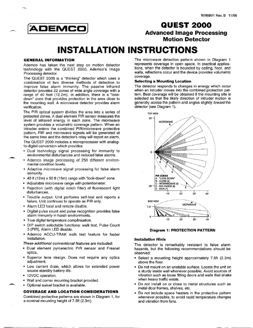
routes. After the ÒWalk-TestÓ is complete, the LED may be
PROBLEM CAUSE REMEDY
Intermittent
Alarm
Rapid temperature
change. Check for
electric or gas
heaters, open
flames, electric
arcs, etc.
Locate source and
reposition detector.
Drafts causing
drapes, light
fixtures, display
material to move.
Eliminate source of
motion.
PIR does not
appear to be
operating
Polling loop voltage
supplied to detec-
tor is inadequate,
intermittent or
polarity reversed.
Assure that proper
polarity is supplied and
that wiring is intact (no
opens or shorts) and
connection secure.
Check for presence of
8Ð11V PP at terminals
of unit. If too low, polling
loop run to control may
be excessive for the
wire gauge used, or
polling loop current
drain may be excessive.
Increase wire gauge or
add Polling loop exten-
der module to location
in the loop where volt-
age boost is necessary
and connect it to a
power source.
Alternatively, the detec-
tor can be tested using
a 9-volt source (such as
a 9-volt battery or a 9-
volt power supply).
LED
inoperative
LED disable
jumper is on Remove LED disable
jumper
LED malfunc-
tion.Check for
broken shorted
leads.
Return unit for service.
Repositioned fur-
niture or
equipment in the
protected area.
Caution customer about
layout changes.
Reposition detector.
Mounting surface
is unstable. A few
degrees of verti-
cal shift can
change range
substantially.
Mount on
secure surface.
Trouble
Code
Improper ID code.
or PIR not
ÒLearnedÓ.
Set DIP swiitches1Ð7 to
proper code, or ÒLearnÓ
PIR serial No.
Detection
Area
Changes
THE LIMITATIONS OF YOUR PASSIVE
INFRARED MOTION DETECTOR
While the Intrusion Detector is a highly reliable intrusion
detection device, it does not offer guaranteed protection
against burglary. Any Intrusion Detection device is subject
to compromise or failure to warn for a variety of reasons:
¥ Passive Infrared Motion Detectors can only detect intru-
sion within the designed ranges as diagrammed in this
installation manual.
¥ Passive Infrared Motion Detectors do not provide volu-
metric area protection. They do create multiple beams
of protection, and intrusion can only be detected in
unobstructed areas covered by those beams.
¥ Passive Infrared Detectors cannot detect motion or
intrusion that takes place behind walls, ceilings, floors,
closed doors, glass partitions, glass doors, or windows.
¥ Mechanical tampering, masking, painting or spraying of
any material on the lenses, windows or any part of the
optical system can reduce the detection ability of the
Passive Infrared Motion Detector.
¥ Passive Infrared Detectors sense changes in tempera-
ture; however, as the ambient temperature of the pro-
tected area approaches the temperature range of 90¡ to
105¡F (32¡ to 40¡C), the detection performance can
decrease.
¥ This Passive Infrared Detector will not operate without
appropriate DC power connected to it, or if the DC
power is improperly connected (i.e., reversed polarity
connections).
¥ Passive Infrared Detectors, like other electrical devices,
are subject to component failure. Even though this
equipment is designed to last as long as 10 years, the
electronic components in it could fail at any time.
We have cited some of the most common reasons that a
Passive Infrared Motion Detector can fail to catch intrusion.
However, this does not imply that these are the only rea-
sons, and therefore it is recommended that weekly testing
of this type of unit, in conjunction with weekly testing of the
entire alarm system, be performed to ensure that the
detectors are working properly.
Installing an alarm system may make the owner eligible for
a lower insurance rate, but an alarm system is not a sub-
stitute for insurance. Homeowners, property owners and
renters should continue to act prudently in protecting them-
selves and continue to insure their lives and property. We
continue to develop new and improved protection devices.
Users of alarm systems owe it to themselves and their
loved ones to learn about these developments.
ADEMCO SIX YEAR Limited Warranty
Alarm Device Manufacturing Company, a Division of Pittway
Corporation, and its divisions, subsidiaries and affiliates
("Seller"), 165 Eileen Way, Syosset, New York 11791, war-
rants this PIR/Microwave Detector to be in conformance with
its own plans and specifications and to be free from defects
in materials and workmanship under normal use and service
for 72 months from the date stamp control on the product.
Seller's obligation shall be limited to replacing, free of charge
for materials or labor, a detector which is proved not in com-
pliance with Seller's specifications or proves defective in
materials or workmanship under normal use and service.
Seller shall have no obligation under this Limited Warranty or
otherwise if the detector is altered or improperly repaired or
serviced by anyone other than Ademco factory service. In
case of defect, return the detector to ADI, or an authorized
Ademco distributor for an immediate replacement.
THERE ARE NO WARRANTIES, EXPRESS OR IMPLIED,
OF MERCHANTABILITY, OR FITNESS FOR A PARTICU-
LAR PURPOSE OR OTHERWISE, WHICH EXTEND
BEYOND THE DESCRIPTION ON THE FACE HEREOF. IN
NO CASE SHALL SELLER BE LIABLE TO ANYONE FOR
ANY CONSEQUENTIAL OR INCIDENTAL DAMAGES FOR
BREACH OF THIS OR ANY OTHER WARRANTY,
EXPRESS OR IMPLIED, OR UPON ANY OTHER BASIS OF
LIABILITY WHATSOEVER, EVEN IF THE LOSS OR DAM-
AGE IS CAUSED BY THE SELLER'S OWN NEGLIGENCE
OR FAULT.
Seller does not represent that its detector may not be com-
promised or circumvented; that the detector will prevent any
personal injury or property loss by burglary, robbery, fire or
otherwise; or that the detector will in all cases provide ade-
quate warning or protection. Buyer understands that a prop-
erly installed and maintained alarm may only reduce the risk
of a burglary, robbery, fire or other events occurring without
providing an alarm, but it is not insurance or a guarantee that
such will not occur or that there will be no personal injury or
property loss as a result. CONSEQUENTLY, SELLER
SHALL HAVE NO LIABILITY FOR ANY PERSONAL
INJURY, PROPERTY DAMAGE OR OTHER LOSS BASED
ON A CLAIM THE DETECTOR FAILED TO GIVE WARN-
ING. However, if Seller is held liable, whether directly or indi-
rectly, for any loss or damage
arising under this Limited
Warranty or otherwise, regardless of cause or origin,
Seller's maximum liability shall not in any case exceed
the purchase price of the detector, which shall be the
complete and exclusive remedy against Seller. This
warranty replaces any previous warranties and is the
only warranty made by Seller on this detector. No
increase or alteration, written or verbal, of the obliga-
tions of this Limited Warranty is authorized.
disabled (plug in place).
Troubleshooting
Table 1. Installation Guide for Lenses
STAN-
DARD LENSES
PROTECTION RANGE
you must also mask the look down window.
Wi
ring Connections
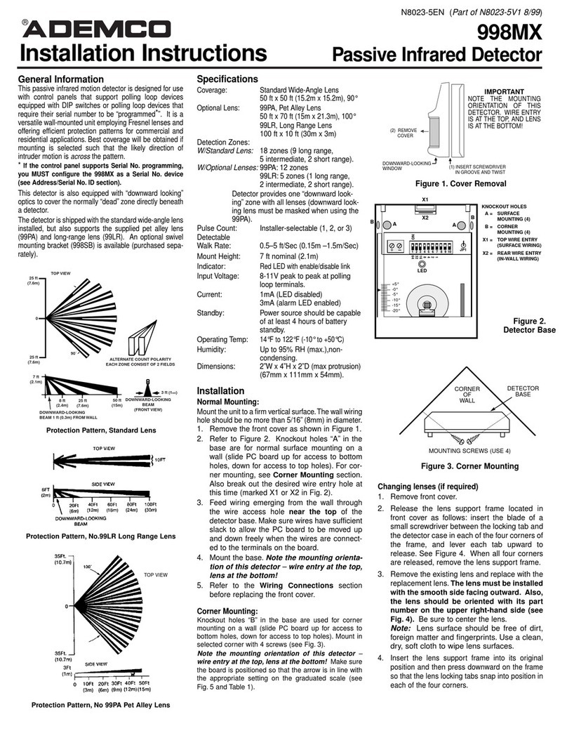
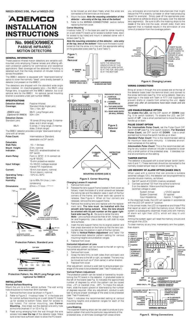
Bring wires in through the wire access slot at the top of the
detector base (near the terminal block) and connect to the
screw terminals (see fig. 5 for wiring terminals). Seal all open-
ing in the base with foam or RTV (not supplied) to prevent
drafts or insects from entering the unit.
Apply power only after
the wiring
connections have been made and are inspected.
Address/Serial No. ID
This PIR includes a DIP switch for use in setting the ID num-
ber when the associated control does not support devices
which can be ÒlearnedÓ. See the Point ID Programming Chart
for DIP switch settings.
IMPORTANT: If the PIR is to be used with a control that
supports serial number learning, you MUST configure
this PIR as a Serial No. device during the zone program-
ming procedure (see the control panelÕs Installation
Instructions). For manual entry, the serial number can be
found on the bar code label on the left-hand corner of the PC
board (see Fig. 5) Before ÒlearningÓ this PIR, make sure
jumper JP1 is cut and that the DIP switch is set with all
positions OFF.
Pulse Count Option
This detector includes Pulse count circuitry that provides sta-
bility in adverse environments to minimize false alarms.
Selectable 1, 2 or 3 event pulse count is provided by position-
ing a jumper across the appropriate pulse count terminals
shown in Figure 5. When programmed for 2 or 3 event pulse
count, the detector will signal an alarm within 3 to 4 steps,
since the processing logic requires more complex motion than
just a momentary event. When the detector verifies an intru-
sion, the LED lights for approximately 1 to 3 seconds.
LED Enable/Disable Option
The Alarm LED is disabled when the LED enable/disable plug
is in place). To enable the LED, remove the LED enable/dis-
able plug (see Fig. 5). To prevent loss of the plug we suggest
you install it on one pin when the plug is not in use. Note: The
LED is viewed through the front cover lens.
If desired, the LED may be controlled from a remote location, as
follows: Remove the LED enable/disable plug. Connect a
switched line to the right-hand pin (#1) of the two LED pins (see
Fig. 5) which can be grounded or opened. Grounding pin #1 will
disable the LED, disconnecting it from ground will enable the
LED.
Tamper Switch
Removal of the cover causes a tamper switch to open. The
panel is automatically notified via the polling loop when this
event occurs.
Test Procedures
Important: Two-minute warm-up time is required after apply-
ing power. Testing should be conducted with the protected
area cleared of all people. Disarm the protective systemÕs con-
trol during the test procedure to prevent reporting of unwanted
alarms.
1. Remove front cover and install the jumper across Pulse
Count pins "1" (this will provide instant response). The
LED must be enabled at this time (LED jumper plug
removed).
2. Replace front cover and walk through protective zones,
observing that the detectorÕs LED lights whenever
motion is detected. (The LED serves as a Walk-Test
Indicator during this procedure.
Note: In the Instant mode, the LED stays lit for approxi-
mately 1-3 seconds after detecting motion.
3. Test the downward looking zone by walking along the
wall directly beneath the detector (this does not apply to
the Pet Alley lens or the standard lens masked to act as
a Pet Alley lens, which should have the downward-look-
ing window on the detector masked.
4. If pulse count is to be used, set the pulse count jumper
to desired setting and repeat the walk test procedure.
With pulse count on, the LED serves as an alarm
Indicator.
The absolute range of all PIR units is subject to variation
because of different types of clothing, backgrounds and
ambient temperature. For this reason, ensure that the most
likely intruder routes are well within the PIRÕs protective
zones and that walk-testing is carried out along these
Figure 5. INTERIOR VIEW
@@@@@@@@e?
@@@@@@@@e?
@@h?
@@h?
@@h?
@@h?
@@h?
@@h?
@@@@@@@@e?@@@@@@@@?e@@@@@@@@e?@@@@@@@@?e@@@@@@@@e?@@@@@@@@?e@@@@@@@@e?@@@@@@@@?e@@@@@@@@e?@@@@@@@@?e@@@@@@@@e?@@@@@@@@?e@@@@@@@@e?@@@@@@@@?e
@@@@@@@@e?@@@@@@@@?e@@@@@@@@e?@@@@@@@@?e@@@@@@@@e?@@@@@@@@?e@@@@@@@@e?@@@@@@@@?e@@@@@@@@e?@@@@@@@@?e@@@@@@@@e?@@@@@@@@?e@@@@@@@@e?@@@@@@@@?e
@@@@@@@@
@@@@@@@@
@@
@@
@@
@@
@@
@@
@@
@@
@@
@@
@@
@@
@@
@@
?@@
?@@
?@@
?@@
?@@
?@@
?@@@@@@@@
?@@@@@@@@
?@@@@@@@@?e@@@@@@@@e?@@@@@@@@?e@@@@@@@@e?@@@@@@@@?e@@@@@@@@e?@@@@@@@@?e@@@@@@@@e?@@@@@@@@?e@@@@@@@@e?@@@@@@@@?e@@@@@@@@e?@@@@@@@@?e@@@@@@@@
?@@@@@@@@?e@@@@@@@@e?@@@@@@@@?e@@@@@@@@e?@@@@@@@@?e@@@@@@@@e?@@@@@@@@?e@@@@@@@@e?@@@@@@@@?e@@@@@@@@e?@@@@@@@@?e@@@@@@@@e?@@@@@@@@?e@@@@@@@@
@@g
@@g
@@g
@@g
@@g
@@g
@@@@@@@@
@@@@@@@@
@@
@@
@@
@@
@@
@@
@@
@@
PULSE
COUNT
SERIAL
NUMBER
TAMPER
SWITCH
LONG RANGE - 998-LR
PROTECTION RANGE
Important: When using the Long Range lens,
set the PIR for Instant response (Pulse Count 1)
PET ALLEY LENS– 998-PA
PROTECTION RANGE
Mtg 15' 20' 30' 40' 50'
Height (4.6m) (6m) (9m) (12m) (15m)
8.5Ft -20¡ -16¡ -11¡ -8¡ -7¡
(2.6m)
8Ft -20¡ -15¡ -10¡ -8¡ -6¡
(2.4m)
7Ft -16¡ -12¡ -8¡ -6¡ -5¡
(21m)
6Ft -13¡ -10¡ -6¡ -5¡ -4¡
(1.8m)
Mtg 20' 40' 60' 80' 100'
Height (6m) (12m) (18m) (24m) (30.4m)
8.5Ft -15¡ -9¡ -6¡ -5¡ -5¡
(2.6m)
8Ft -14¡ -8¡ -6¡ -5¡ -4¡
(2.4m)
7Ft -11¡ -6¡ -5¡ -4¡ -4¡
(21m)
6Ft -8¡ -5¡ -4¡ -3¡ -3¡
(1.8m)
–––––
Vertical Pattern Setting
–––––
––––––––
Vertical Pattern Setting
––––––––
TO THE INSTALLER
Regular maintenance and inspection (at least annual-
ly) by the installer and frequent testing by the user are
vital to continuous satisfactory operation of any alarm
system.
The installer should assume the responsibility of
developing and offering a regular maintenance pro-
gram to the user, as well as acquainting the user with
the proper operation and limitations of the alarm sys-
tem and its component parts. Recommendations must
be included for a specific program of frequent testing
(at least weekly) to insure the systemÕs operation at all
@@@@@@@@e?
@@@@@@@@e?
@@h?
@@h?
@@h?
@@h?
@@h?
@@h?
@@@@@@@@e?@@@@@@@@?e@@@@@@@@e?@@@@@@@@?e@@@@@@@@e?@@@@@@@@?e@@@@@@@@e?@@@@@@@@?e@@@@@@@@e?@@@@@@@@?e@@@@@@@@e?@@@@@@@@?e@@@@@@@@e?@@@@@@@@?e@@@@@@@@e?@@@@@@@@?e@@@@@@@@e?@@@@@@@@?e@@@@@@@@e?@@@@@@@@?e@@@@@@@@e?@@@@@@@@?e@@@@@@@@e?@@@@@@@@?e@@@@@@@@e?@@@@@@@@?e@@@@@@@@e?@@@@@@@@?e@@@@@@@@e?
@@@@@@@@e?@@@@@@@@?e@@@@@@@@e?@@@@@@@@?e@@@@@@@@e?@@@@@@@@?e@@@@@@@@e?@@@@@@@@?e@@@@@@@@e?@@@@@@@@?e@@@@@@@@e?@@@@@@@@?e@@@@@@@@e?@@@@@@@@?e@@@@@@@@e?@@@@@@@@?e@@@@@@@@e?@@@@@@@@?e@@@@@@@@e?@@@@@@@@?e@@@@@@@@e?@@@@@@@@?e@@@@@@@@e?@@@@@@@@?e@@@@@@@@e?@@@@@@@@?e@@@@@@@@e?@@@@@@@@?e@@@@@@@@e?
@@@@@@@@
@@@@@@@@
@@
@@
@@
@@
@@
@@
@@
@@
@@
@@
@@
@@
@@
@@
@@
@@
@@
@@
@@
@@
@@
@@
@@
@@
@@
@@
@@
@@
@@
@@
@@
@@
@@
@@
@@
@@
@@
@@
@@
@@
@@
@@
@@
@@
@@
@@
@@
@@
@@
@@
@@
@@
@@
@@
@@
@@
@@
@@
@@
@@
@@
@@
@@
@@
@@
@@
@@
@@
@@
@@
@@
@@
@@
@@
@@
@@
@@
@@
@@
@@
@@
@@
@@
@@
@@
@@
@@
@@
@@
@@
@@
@@
@@
@@
@@
@@
@@
@@
@@
@@
@@
@@
@@
@@
@@
@@
@@
@@
@@
@@
@@
@@
@@
@@
@@
@@
@@
@@
@@
@@
@@
@@
@@
@@
@@
@@
@@
@@
@@
@@
@@
@@
@@
@@
@@
@@
@@
@@
@@
@@
@@
@@
@@
@@
@@
@@
@@
@@
@@
@@
@@
@@
@@
@@
@@
@@
@@
@@
@@
@@
@@
@@
@@
@@
@@
@@
?@@
?@@
?@@
?@@
?@@
?@@
?@@@@@@@@
?@@@@@@@@
?@@@@@@@@?e@@@@@@@@e?@@@@@@@@?e@@@@@@@@e?@@@@@@@@?e@@@@@@@@e?@@@@@@@@?e@@@@@@@@e?@@@@@@@@?e@@@@@@@@e?@@@@@@@@?e@@@@@@@@e?@@@@@@@@?e@@@@@@@@e?@@@@@@@@?e@@@@@@@@e?@@@@@@@@?e@@@@@@@@e?@@@@@@@@?e@@@@@@@@e?@@@@@@@@?e@@@@@@@@e?@@@@@@@@?e@@@@@@@@e?@@@@@@@@?e@@@@@@@@e?@@@@@@@@?e@@@@@@@@e?@@@@@@@@
?@@@@@@@@?e@@@@@@@@e?@@@@@@@@?e@@@@@@@@e?@@@@@@@@?e@@@@@@@@e?@@@@@@@@?e@@@@@@@@e?@@@@@@@@?e@@@@@@@@e?@@@@@@@@?e@@@@@@@@e?@@@@@@@@?e@@@@@@@@e?@@@@@@@@?e@@@@@@@@e?@@@@@@@@?e@@@@@@@@e?@@@@@@@@?e@@@@@@@@e?@@@@@@@@?e@@@@@@@@e?@@@@@@@@?e@@@@@@@@e?@@@@@@@@?e@@@@@@@@e?@@@@@@@@?e@@@@@@@@e?@@@@@@@@
@@g
@@g
@@g
@@g
@@g
@@g
@@@@@@@@
@@@@@@@@
@@
@@
@@
@@
@@
@@
@@
@@
@@
@@
@@
@@
@@
@@
@@
@@
@@
@@
@@
@@
@@
@@
@@
@@
@@
@@
@@
@@
@@
@@
@@
@@
@@
@@
@@
@@
@@
@@
@@
@@
@@
@@
@@
@@
@@
@@
@@
@@
@@
@@
@@
@@
@@
@@
@@
@@
@@
@@
@@
@@
@@
@@
@@
@@
@@
@@
@@
@@
@@
@@
@@
@@
@@
@@
@@
@@
@@
@@
@@
@@
@@
@@
@@
@@
@@
@@
@@
@@
@@
@@
@@
@@
@@
@@
@@
@@
@@
@@
@@
@@
@@
@@
@@
@@
@@
@@
@@
@@
@@
@@
@@
@@
@@
@@
@@
@@
@@
@@
@@
@@
@@
@@
@@
@@
@@
@@
@@
@@
@@
@@
@@
@@
@@
@@
@@
@@
@@
@@
@@
@@
@@
@@
@@
@@
@@
@@
@@
@@
@@
@@
@@
@@
@@
@@
@@
@@
@@
@@
@@
@@
Mounting Height: 3 Ft. - 3.5 Ft. (0.9 - 1m)
Vertical Pattern Setting (for all ranges): +2¡
Important: Be sure to affix the provided masking
label over the look-down window.
ALARM DEVICE MFG. CO.
A DIVISION OF PITTWAY CORPORATION
165 Eileen Way, Syosset, N.Y. 11791
Copyright © 1995 PITTWAY CORPORATION


