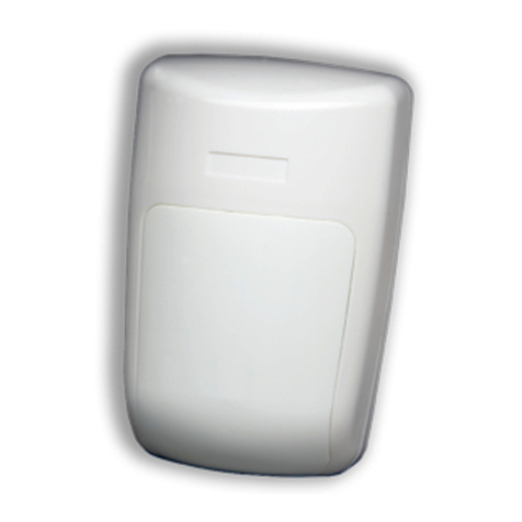
Bentel Security Visus99 User manual

ITALIANO
L’area di copertura del sensore è controllata rispettivamente (vedi fig. 3); Visus99Visus99: mediante 24 fasci
posti su 4 livelli. Visus99/CVisus99/C: mediante 8 fasci disposti su 7 livelli. Visus99/LVisus99/L: mediante 11 fasci disposti su 5 livelli. Visus99/TVisus99/T:
mediante 11 fasci su 11 livelli ad effetto tenda. Ogni fascio è duplicato dal sensore piroelettrico duale che genera due segnali
differenziali, raddoppiando l’efficienza di rilevazione degli allarmi e minimizzando altri segnali di disturbo. Visus99-Mic, Visus99/Visus99-Mic, Visus99/
C-Mic, Visus99/L-Mic, Visus99/T-MicC-Mic, Visus99/L-Mic, Visus99/T-Mic versioni con microfono.
Copertura
Rilevamento mediante sensore piroelettrico duale insensibile alle variazioni di Temperatura.Alta immunità ai
disturbi esterni elettromagnetici o ambientali.Copertura antistrisciamento.Regolazione manuale della sensibilità e compensazione termica
della soglia di allarme per un corretto funzionamento anche in ambienti con forti escursioni termiche. Versione con microfono per l’ascolto
ambientale. Il segnale acustico captato viene amplificato e riportato sui morsetti MIC(positivo) e GND (Negativo) (vedi Fig.1b PCB
con microfono). Semplice installazione.Conforme alle norme CEI 79-2-2aEd. 1993.Livello di prestazione I°.
Descrizione
Il Visus99 è stato realizzato per l’uso all’interno di edifici, sia di civile abitazione che commerciali ed è consigliabile montarlo
ad un’altezza di 2,1 m. Evitare l’esposizione del sensore alla luce diretta e a forti correnti d’aria. Si ricorda altresì che oggetti ingombranti, posti frontalmente
alsensore,modificanoinmodosignificativoilcampodicopertura.FacendoriferimentoalleFig.1-2,ilsensorepuòesseremontatoapareteutilizzandoifori
predisposti sul fondo o la staffa 1111. Può altresì essere fissato ad angolo mediante i fori 99, infine può essere montato utilizzando lo snodo opzionale.
Apertura coperchio e ingresso cavi.Apertura coperchio e ingresso cavi. Inserire un cacciavite nel foro situato alla base del fondo del sensore, premere e tirare
il coperchio. Mediante un cacciavite aprire la predisposizione superiore del fondo da cui far entrare il cavo.
Montaggio a parete con staffa.Montaggio a parete con staffa. Con un cacciavite premere sul gancio della staffa (1010) posto nella sua sede sul fondo del
sensore e sganciare la staffa stessa. Fissare la staffa alla parete utilizzando gli appositi fori. Agganciare il fondo sulla staffa.
Montaggio a parete o ad angolo senza staffa.Montaggio a parete o ad angolo senza staffa. Selezionare ed aprire le predisposizioni per le viti sul fondo del sensore (vedi Fig. 1-2).
Montaggio con snodo.Montaggio con snodo. Fissare la base dello snodo alla parete e la staffa del sensore allo snodo mediante la vite fornita (vedi Fig. 1-2).
Le seguenti fasi sono comuni a tutti i tipi di montaggio.Le seguenti fasi sono comuni a tutti i tipi di montaggio. Eseguire i collegamenti sulla morsettiera seguendo le indicazioni
relative. Fissare il coperchio del sensore. Nel caso fosse richiesto è possibile bloccare il coperchio mediante la vite 66. Alimentare
il sensore e verificarne il corretto funzionamento controllando l’accensione del Walk-test-LED.
Installazione
E’ possibile variare l’inclinazione verticale dei fasci di copertura (da -2oa -10o) allentando la
vite 44 e spostando verticalmente la scheda stessa, fino ad ottenere la copertura desiderata.La variazione in gradi può essere letta
mediante la scala graduata 1616, (vedi Fig.1), usando come riferimento la tacca posta a lato sul fondo del sensore.
Orientamento verticale
La regolazione della sensibilità del sensore si effettua tramite il trimmer 1717, mentre
quella del microfono si effettua tramite il trimmer 2020, (Fig. 1); ruotandolo nel verso indicato dalla freccia sul circuito
stampato, la sensibilità aumenta.
Regolazione sensibilità
Il Walk-test-LED 15 (vedi Fig. 1) si accende ogni volta che viene raggiunta la condizione di allarme.
Il collaudo si effettua camminando di fronte al sensore seguendo un percorso a zig-zag.Il Walk-test-LED può essere escluso rimuovendo
il ponticello 14 (vedi Fig.1). In base alle caratteristiche dell’area da coprire si può aumentare o diminuire la sensibilità del sensore.
Walk-test-led (WTL)
Il collegamento al sensore deve essere effettuato mediante cavo schermato. Un capo dello schermo
deve essere collegato ad una massa in centrale, mentre l’altro deve rimanere appeso. Di seguito viene riportata la descrizione della morsettiera:
Collegamenti
Visus99Visus99
®
ESPAÑOL
ISTVISUS995.1230107P7.0
SENSORE INFRAROSSO PASSIVO
DETECTOR PASIVO INFRARROJO
PASSIVE INFRARED DETECTOR
NC Contatto di Allarme
Normalmente Chiuso TAMP Contatto Antisabotaggio
Normalmente Chiuso +12- Alimentazione Sensore MIC
GND Uscita Microfono
Detección a base de un sensor dual piroeléctrico con inmunidad a las variaciones de temperatura. Alto nivel de
inmunidad en contra de las falsas alarmas y los campos electromagnéticos.Detección de los movimientos furtivos. Posibilidad de
regular manualmente la sensibilidad y la compensación de la temperatura mínima de alarma, lo que permite el buen funcionamiento
deldetectorenzonascongrandesvariacionesdetemperatura. Fácilinstalación.Versiónequipadodeunmicrófono capabledepercibir
el ruido en su ambiente de instalación. La señal acústica percibida serà amplificada y conectada a las bornas MIC (positiva) y GND
(negativa) (Véase Fig. 11bb Tarjeta con el micrófono). De acuerdo con las normas CEI 79-2, segunda edición - 1993. Nivel 7.
Para la cobertura del detector (véase fig.3); Visus99:24 rayos en 4 niveles. Visus99/C:8 rayos en 7 niveles.
Visus99/L:11 rayos en 5 niveles. Visus99/T:11 rayos en 11 niveles (lente cortina). El sensor piroeléctrico dual produce dos
señales distintos para cada rayo, lo que hace que la detección sea dos veces más eficiente y lleva al máximo la inmunidad a
interferencias. Visus99-Mic, Visus99/C-Mic, Visus99/L-Mic, Visus99/T-MicVisus99-Mic, Visus99/C-Mic, Visus99/L-Mic, Visus99/T-Mic versiones con micrófono.
Cobertura
Descripción
ISO 14001
9191.BNT2 ISO 14001
IT-52588
ISO 9001
9105.BNT1 ISO 9001
IT-52587

EldetectorVisus99hasido diseñado para utilizarse al interiorderesidenciasyedificioscomerciales.Eldetector
se debe instalar a unos 2.1 metros de altura. Evitar la instalación en lugares donde el dispositivo esté expuesto a la luz directa o a
fuertescorrientesdeaire.Siempre tener en cuenta el hecho de que los objetos grandes colocados delante del detector reducen su
cobertura.Eldetectorsepuedeinstalarenlaparedconlaayudadelosagujerosciegosdelaplacatrasera(véaseFig.1-2)oconla
ayuda del soporte de instalación 11. El detector se puede también instalar en un rincón con la ayuda de los agujeros ciegos 9. Para
la instalación en la pared se puede también utilizar un soporte giratorio (opcional). Remover la tapa y abrir los agujeros ciegos.
Introducirundestornilladorpequeñoconpuntadehojaplanaenelagujeroqueseencuentraenlaparteinferiordeldetector,empujar
ysacarlatapa.Servirsetambién del destornillador para abrir losagujerosciegosqueseencuentranen la parte superior de laplaca
trasera.Instalación enla paredcon soportede instalación.Empujarlalengüeta(10)para sacar laplaca trasera delsoporte de
instalación.Fijarelsoporteenlaparedconlaayudadelostornillossuministrados.Fijarlaplacatraseraenelsoportedeinstalación.
Montaje en la pared o en un rincón sin soporte de instalación.Montaje en la pared o en un rincón sin soporte de instalación. Abrir los agujeros ciegos correspondientes (véase Fig.1-2)
Montaje en la pared con soporte giratorio.Montaje en la pared con soporte giratorio. Fijar la placa trasera del soporte giratorio en la pared y fijar el soporte de instalación del
detector en el soporte giratorio con la ayuda de los tornillos suministrados (véase Fig.1-2). Las etapas presentadas a continuación seLas etapas presentadas a continuación se
refieren a todos los tipos de instalaciónrefieren a todos los tipos de instalación. Respetar las instrucciones de conexión. Volver a montar la tapa del detector. La tapa se fija en la placa
trasera con la ayuda del tornillo 66. Alimentar el detector y verificar su correcto funcionamiento con la ayuda del LED de prueba movible (walk test).
Para regular el ajuste vertical con el fin de obtener la cobertura deseada (entre -2oy -10o) aflojar el
tornillo 44 y cambiar la posición vertical de la tarjeta de circuitos impresos hasta obtener la cobertura deseada. La variación en grados se
puede leer en la escala 1616, Fig.1. Utilizar como referencia la muesca que se encuentra en la parte lateral de la placa trasera del detector.
Ajuste vertical
Instalación
El nivel de sensibilidad del detector se puede regular con la ayuda del trimer 17, Fig.1. Para
aumentar el nivel de sensibilidad, hacer girar la arandela del trimer en la dirección indicada por la flecha presente en el circuito
impreso. Para aumentar la sensibilidad del micrófono hacer girar la arandela del trimer 20 (M) en la dirección indicada por la
flecha presente en el circuito impreso.
Ajus te de la sensibilidad
Description Detection by means of dual pyroelectric sensor immune to temperature changes.High immunity against
false alarms and electro-magnetic fields.Sneak cover. Manual adjustment of sensibility, temperature compensation of alarm
threshold for proper functioning in environments with notable temperature changes. A version is equipped with a microphone
capable of picking up ambient noises. The audible signal is amplified and carried to the MIC(positive) and GND(negative)
terminals. See Figure 1b1b (PCB with microphone).Trouble-free installation.Complies with CEI 79-2-2nd Ed. 1993. Level 1.
ENGLISH
For detector coverage (see fig.3); Visus99: 24 beams on 4 levels. Visus99/C: 8 beams on 7 levels.
Visus99/L:11 beams on 5 levels.Visus99/T:11beamson11levels(curtainlens). Thedualpyroelectric sensorgenerates
twodifferentialsignalsforeach beam, thus doubling the alarmdetectionefficiencyandmaximizinginterference immunity.
The versions with a microphone are Visus99-Mic, Visus99/C-Mic, Visus99/L-Mic, Visus99/T-Mic.
Coverage
The Visus99 is designed for indoor use in homes and commercial buildings. The detector should be mounted
at a height of 2.1 m.Avoid locations that are subject to direct light and high air flow.Please remember that large objects placed in front of the
detector will reduce detector coverage.The detector may be wall mounted by means of the knockouts on the backplate see Fig. 1-2 or by
means of the bracket 11. The detector may be corner mounted by means of the knockouts 9. A wall-mount swivel is also available.
Removal of cover and knockouts.Removal of cover and knockouts. Insert a small flat blade screwdriver into the hole at the bottom of the case, push open
and remove the cover. Use the screwdriver to remove the upper wire knockouts on the backplate.
Wall mount with bracket.Wall mount with bracket. Push the bracket tab (1010) up to free the bracket from the backplateup to free the bracket from the backplate. Mount the bracket
to the wall using the screws supplied. Snap the backplate into place on the bracket.
Wall or corner mount without bracket.Wall or corner mount without bracket. Remove the appropriate knockouts see Fig. 1-2.
Wall mount with swivel.Wall mount with swivel. Fit the backplate of the swivel to the wall and then fit the detector bracket to the swivel, use the
screws supplied Fig. 1-2.
The following steps are for all mounting types.The following steps are for all mounting types. Carefully follow the connection instructions. Refit the detector cover. It is possible to
screw the cover to the backplate by means of the screw 6. Power the detector and verify proper operation by means of the Walk-test-LED.
Installation
To set the vertical adjustment for the required coverage (from -2oto -10o) loosen the
retaining screw 44 move the circuit board vertically to achieve the required coverage. The variation may be read on a
graduated scale 1616, Fig.1. Use the notch on the side of the detector backplate as reference.
Vertical adjustment
Use the trimmer 1717, Fig. 1, to set the sensitivity threshold. To increase sensitivity, turn
the trimmer in the direction of the arrow on the printed circuit. To increase sensitivity of the microphone, turn the trimmer
20 (M)20 (M) in the direction of the arrow on the printed circuit.
Sensitivity adjustment
Create motion in the entire area, the Walk-test-LED 15 Fig. 1 will light each time
alarm status is detected. The walk-test-LED may be bypassed by removing the jumper 14 Fig. 1.It is possible to
increase or decrease sensitivity according to the characteristics of the protected area.
Walk-test-led (WTL)
Connections must be carried out with shielded cable. One end of the cable must be
connected to ground on the control panel, and the other left floating. Following is a description of the terminal board.
Connections
Al moverse en el área, el LED de prueba movible 1515, Fig.1, se enciende cada vez
que aparece una condición de alarma. Para desviar el LED quitar el jumper 1414, Fig.1. Existe la posibilidad de aumentar o
reducir la sensibilidad en función de las características de la zona protegida.
Led prueba movible (WTL)
NC Contacto Alarma
Normalmente Cerrado TAMP Contacto Antisabotaje
Normalmente Cerrado +12- Alimentación del
sensor MIC
GND Bornes del Micrófono
NC Normally Closed Alarm
Contact TAMP Normally Closed Tamper
Switch +12- Power Supply MIC
GND Microphone Terminals

Identificazione delle parti - Identificacion de las partes - Parts.
Fig. 1
CARATTERISTICHE
TECNICHE CARATERÍSTICAS
TÉCNICAS TECHNICAL FEATURES
Tensione alimentazione Voltaje de entrada Input voltage 10÷15 V _
Corrente assorbita Consumo de corriente el. Current absorption 12 mA (Imax=Imin)
Corrente assorbita(PCB
con microfono) Consumo de corriente
el.(PCB con micrófono) Current absorption
(PCB with a microphone) 14 mA (Imax=Imin)
Sensibilità microfono Sensibilidad micrófono Microphone sensitivity -24 dB
Banda passante microfono Respuesta en frecuencia
micrófono Microphone Frequency
response 300÷4000Hz
Relè di allarme Relè de alarma Alarm relay NC
Tamper Relè antisabotaje Tamper NC
Portata: Visus99 - C - L - T Alance: Visus99 - C - L - T Range: Visus99 - C - L - T 12 - 20 - 40 - 12 m
Dimensioni (L x A x P) Dimenciones (An X Al x P) Dimensions (W x H x D) I55 x 91 x 47 mm
Grado di protezione
involucro Protección ofrecida por la
caja Case protection grading IP50
Peso Peso Weight 72 g
Temperatura di
funzionamento Temperatura de
funcionamiento Operating temperature 5 ÷ 40 °C
1Coperchio in ABS-Tapa de ABS-Cover in
ABS
2Tappo in polietilene-Ventana de polietileno-
Polythene window
3Lente- Lens
4
Vite di bloccaggio PCB su fondo e per
regolazione verticale.-Tornillo retenedor para
fijar la PCB en la placa trasera y para ajuste
vertical.-Retaining screw for PCB to backplate
and for vertical adjustment.
5Circuito stampato (PCB)-Tarjeta de circuitos
impresos (PCB)-Printed Circuit (PCB)
6Vite di chiusura coperchio sul fondo-Tornillo
para fijar la tapa en la placa trasera-Screw for
fitting cover to backplate
7Fondo in ABS-Placa trasera de ABS-
Backplate in ABS
8Bassofondo per foro passacavi-Agujeros
ciegos para cableado-Cable knockouts
9Bassofondi per fori di fissaggio ad angolo-
Agujeros ciegos para montaje en un rincón-
Knockouts for corner mounting
10 Sede per gancio staffa-Lengueta del soporte
de instalaciòn- Bracket tab set
11 Staffa in ABS per fissaggio a muro-
Soporte de ABS para instalación en la
pared-Wall mount bracket in ABS
12 Viti per fissaggio staffa a muro-Tornillo
para fijar el soporte en la pared-Screw for
fixing btaket to wall
13 Morsettiera-Placa de bornes-Terminal
board
14 Ponticello Walk Test-Jumper para prueba
movible-Walk Test jumper
15 LED
16 Scala graduata per orientamento verticale-
Escala de ajuste vertical-Vertical
adjustment
17 Trimmer per regolazione sensibilità-Trimer
para ajustar la sensibilidad-Trimmer
sensitivity adjustment
18 Microswitch antisabotaggio-Conmutador
antisabotaje-Tamper switch
19 Microfono, , Micrófono, Microphone
20 Trimmer regolazione sensibilità microfono
Trimer para la sensibilidad del Micrófono,
Microphone Trimmer sensitivity adjustment
21 Cavo schermato- Cable apantallado-
Shielded cable
22 Schermo-Protector-shield
811
12
10
9
7
1
4
56
2
3
-10
-2
13 13
16
15
17
14
18
-10
-2
13 13
16
15
17
14
18
a)
b)
M
IR
19
20
21
22

a)Vista inpianta -Vista desde encima - Topview
b)Vista laterale - Vista lateral- Sideview
c) Antistrisciamento - Cobertura de movimientos furtivos - Sneak cover.
Fig. 3 - Diagrammi di copertura - Esquemas de cobertura -
Coverage diagrams. Fig. 2 - Installazione Instalación -
Installation.
Visus99
Visus99 / C
Visus99 / T
Visus99 / L
Montaggio con snodo-Montaje en la pared
con soporte giratorio-Wall mount with
swivel.
Montaggio ad angolo-Montaje en un rincón-
Wall corner mount.
e
Montaggio a parete con staffa-Montaje en
la pared con la ayuda de un soporte de
instalación-Wall mount with braket.
d
f
-10
-2
(b)
(a)
m
3
3
5 10
2,1
6
6
9
9
12
12
90°
(c)
(b)
(a)
(c)
m
2,1
0
1
510 20
(b)
(a)
0
(c)
2.1
1
42 8 16 40 m
(b)
(a)
m
12
0
2.1
Table of contents
Languages:
Other Bentel Security Security Sensor manuals
Bentel Security
Bentel Security DT800 User manual
Bentel Security
Bentel Security IR 360 User manual
Bentel Security
Bentel Security BL151 User manual
Bentel Security
Bentel Security BMD503 User manual
Bentel Security
Bentel Security FC450IB User manual
Bentel Security
Bentel Security RAY60 User manual
Bentel Security
Bentel Security FC400H User manual

Bentel Security
Bentel Security FC450IB User manual
Bentel Security
Bentel Security DT800 User manual

Bentel Security
Bentel Security ZT100H User manual
