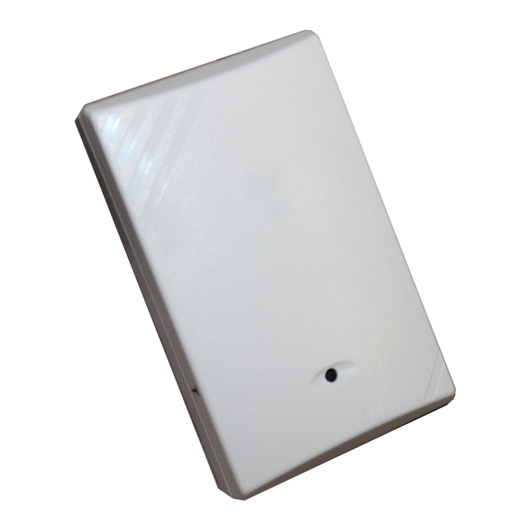
ADEMCO QUEST 2135 User manual

Installation Hints
• Neverinstallthedetectorinanenvironmentthatcausesanalarmcondi-
tion in one technology. Good installations start with the LED OFF when
there is no target motion. It should never be left to operate with the tri-
color LED in a constant or intermittent green, yellow, or red condition.
• Point the unit away from outside traffic (roads/alleys). Remember: Mi-
crowaveenergywillpassthrough glass and most common non-metallic
constructionwalls.Avoidinstallationswhere rotating machines(e.g.,ceil-
ingfans) are normally in operation within thecoverage pattern.
• Pointtheunitaway from glass exposed to the outdoors and objectsthat
may change temperature rapidly. Remember: The PIR detector will
reactto objects rapidly changing temperature within itsfield-of-view.
• Eliminateinterferencefrom nearby outside sources.
Special Instructions
for Installations Containing Pets
TheQUEST 2135 will provide reasonable protection fromnuisance
alarms caused by the following sources:
• Adog up to 100 pounds.
• Two dogs, up to 60 pounds each.
• Up to 10 cats.
• Multiple small rodents, such as rats.
• Randomflyingbirds.
Totake full advantage of the QUEST2135’sPetExclusion Technology,
thefollowingguidelinesshouldbe followed:
• Mount the center of the detector 6-1/2 feet high and adjust the vertical
angleto -5°.
•Set the PIR sensitivity for standard (STD).
• Mount where animals cannot come within six feet of the detector by
climbingon furniture, boxes, or other objects.
• Do not aim the detector at stairways that can be climbed by an animal.
• Adjust the microwave range for the minimum acceptable coverage for
the room in which the detector is installed. Never install with the micro-
waverange exceeding 35 feet.
NOTE: Thisnuisance protection has not been verifiedby Underwriter’s
Laboratories,Inc.
QUEST2135-INST 12/97
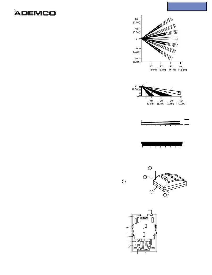
Figure 1. Coverage Pattern Figure 2. Interior View
QUEST 2135
Microwave/PIR Intrusion Detector
Specifications
Input Power: 9 to 15 VDC, 16 mA DC nominal (up to 48 mA DC during
walktesting or trouble conditions).
Standby Power: Nointernalstandby battery.Connect to DC power sources
capable of supplying standby power. Sixteen mA-H re-
quiredfor each hour of standby timeneeded.
Alarm Relay: SilentoperatingNormallyClosedreedrelay.Contacts rated
3watts,125 mA, 28 VDC maximum forDCresistiveloads,
and protected by a 4.7 ohm, 1/2 watt resistor in the com-
mon “C” leg of the relay.
Do not use with capacitive or
inductiveloads.
Operating
Temperature: -40° to +120°F (-40° to +49°C). For U.L. Listed Require-
ments, the temperature range is +32° to +120°F (0° to
+49°C).
Microwave
Frequency: 10.525 Ghz ± 25 MHz
Coverage: 35 ft. by 35 ft. (10.7 m by 10.7 m)
Internal
Pointability: +2°to –10° Vertical,±10°Horizontal.
Tamper: NormallyClosed (withcoveron). Contactsratedat28VDC,
0.125Amax.Connecttampercircuitto24hourprotection
circuit.
Options: QUEST SB2 swivel bracket. (Use of a bracket may re-
ducerange and dead zone area).
NOTE: The protected coverage area is where the microwave and PIR
patternsoverlap.
NOTE: To use the optional Look Down Zone, the Mask must be removed
from the Look Down Lens. Use caution to remove the black
mask only. Do not attempt to remove the white lens assembly.
Do not remove the Mask for pet applications. See Figure 2.
www.PDF-Zoo.com

Page 2
Mounting
1. Selecta location likely to intercept anintrudermovingacross the cover-
age pattern. The surface should be solid and vibration-free. Mounting
height range is six to eight ft. (1.8 to 2.4 m). Recommended mounting
height is 6-1/2 ft. (2 m).
2. Removethe cover.Insertaflatheadscrewdriverintothelockingtabhole
at the bottom front of the detector. Pull the cover up and forward.
3. Removethe circuit board from the base. Loosen the VerticalAdjustment
screw and slide the circuit board down then out.
4. Usingthe baseasatemplate, markthelocation oftheholeson themount-
ingsurface.
5. Route wiring (unpowered) as necessary. Route to the rear of the base
andthroughthe wire entrance.
6. Firmly mount the base to the mounting surface. Return thecircuitboard
tothe base and tighten the Vertical AdjustScrew.
Wiring
Applypower after all connections have beenmade and
inspected. Do not coil excess wiring inside the detector.
•Terminals 1 (-) & 2 (+): Power
limits are 9 to 15VDC. Use no
smallerthan#22 AWGwire pair
(500 feet/150m max) between
the detector and the power
source.
• Terminals 3 & 4: Alarm relay
(reed)contactsratedat 3 watts,
0.125amps, 28VDC maximum
for DC resistive loads and pro-
tected by a 4.7 ohm, 1/2 watt
resistor.
NOTE: Do not use with capacitive or inductive loads.
•Terminals 5 & 8: Spare.
•Terminals 6 & 7: Tamper contacts rated at 28VDC,0.125A.
•Plug the wire entrance hole with the foam plug provided.
LED Operation
The detector uses a tri-color LED to indicate the various alarm and
supervision troubles that may exist. See chart below.
If the detector experiences a Microwave or PIR self-test failure (four pulse
sequence),it is in need of replacement.
During walk testing, the LED will light for the first technology (microwave
or PIR) and then light red to indicate a detector alarm. The LED will not
indicateactivation of the second technologyby lighting its color.
Feature Selection
LED On/Off pins: The ON
positionallows operation of the
tri-color LED. If the tri-color
LEDindication is not desired
after the setup and walk tests
havebeencompleted,place
theplug in the OFFposition.
NOTE: The OFF position does not prevent the tri-color LED from
indicatingasupervisiontrouble condition.
PIR Sensitivity Selection Pins: Selection of the PIR response sensitiv-
ity may be selected by placing the plug across the pins marked STD for
standardorINTfor intermediate mode.
StandardSensitivity:
Therecommended setting for maximum false alarm
immunity. Ittoleratesenvironment extremes on this setting. This setting
is required for pet avoidance.
IntermediateSensitivity:
Therecommended setting for any location where
an intruder is expected to cover only a small portion of the protected area.
Ittolerates normal environments on this setting.This setting will improve
yourintruder catch performance.Intermediate Sensitivity is not
recommended for installations containing pets.
Set-up and Walk Tests
Selectthe vertical starting angle from the chart below:
Adjustthe vertical starting
angleforthedesired mounting
heightandrange.
NOTE: Thepropervertical
anglemustbe
selectedfor
installations
containing pets.
1. Place the LED plug in the ON position and replace the cover.
2. Wait at least two minutes, after applying power, before starting walk
tests.
NOTE: During the warm-up period, the tri-color LED will flash red until
the unit has stabilized and has seen no movement for two
seconds(approximately one to two minutes).When the LED
stops flashing, the detector is ready to be tested. With no motion
in the protection area, the LED should be OFF. If the LED is on,
re-checkthe protection area for disturbances affectingthe
microwave(yellow) or PIR (green) technologies.
Establishing PIR Pattern Coverage
• TurntheMicrowaverange adjust to minimum.
• Walk test across the pattern at its farthest edge, then several times
closertothe detector. Start walking from outside oftheintended protec-
tionarea,and observe the tri-color LED. Theedgeofthepatternis deter-
minedbythefirstgreen,PIRactivationofthe LED (or the first red activa-
tion if the yellow microwave LED activates first).
• Walktestfromtheoppositedirectiontodeterminebothboundaries.The
centerofthepatternshouldbepointedtowardthe center of the intended
protectionarea.
• Slowlybringyour arm up and into thepatterntomarkthelower boundary
onPIRalarm.Performthistaskat10to 20 ft. (3.1 to 6.1 m) from the unit.
Repeat from above for the upper boundary. The center of the pattern
should not be tilted upward.
Ifdesired coverage can not beachieved, try angling the coveragepattern
up or down to assure the pattern is not aimed too high or low. For pet
applicationsdonotadjust below recommended angle.
www.PDF-Zoo.com

Page 3
The angle of the PIR pattern may be vertically positioned between
-10° and +2° by loosening the Vertical Adjust screw and sliding the
circuit board up or down. Moving the board up will angle the pattern
downward.Tightenthescrew snug when positioning is completed.
NOTE: The pattern may be moved ±10° horizontally by moving the lens
to the left or right.
Establishing Microwave Coverage
NOTE: Itis important to wait one minute afterremoving/replacing the
cover so the microwave portion of the detector can settle, and to
wait at least 10 seconds between the following walk testing
procedures.
• The tri-color LED should be OFF before walk testing.
• Walk test across the pattern at the intended coverage’s farthest end.
Startwalkingfromoutside the intended protection area and observe the
tri-color LED. The edge of the microwave pattern is determined by the
first yellow, microwave activation of the LED (or the first red activation if
the green PIR LED activates first).
• Ifadequaterangecannotbereached,increasetheMicro-
waveRangeAdjust slightly. Continue testing (waiting one
minute after removing/replacing the cover) and adjusting
the range until the farthest edge of desired coverage has
beenaccuratelyplaced.
Do not adjust the microwave range higher than required. Doing so
will enable the detector to catch movement outside of the intended
coverage pattern.
• Walktesttheunit from all directions to determine all the detection pattern
boundaries.
Establishing Detector Coverage
• With no motion in the protected area, the tri-color LED should be OFF
beforewalktesting.
• Walk test the unit from all directions to determine the detection bound-
aries. A detector alarm is signaled by the first red activation of the tri-
colorLED after an initial green/yellow activation.
Supervision Features
Thesupervision features function as follows:
•PIR/Microwave: If the PIR or microwave subsystem fails, the tri-color
LEDwill flash red four times per cycle.The complete circuit operation of
these subsystems is checked approximately every 12 hours.
•Default: The detector will default to PIR technology protection if the
microwavesubsystem fails. When defaulting to PIR, thePIR signal pro-
cessing will change from INT to STD.
Other Information
Maintenance: Atleast once a year, the range andcoverage should be
verified. To ensure continual daily operation,the end user should be
instructed to walk through the far end of the coverage pattern. This
ensures an alarm output prior to arming the system.
Pattern Masking: The PIR coverage pattern may be masked using
masking tape or electrical tape on the inside of the lens.
NOTE: Maskingonly eliminates the PIR portion of the coverage and has
noeffectonthe microwave pattern.
U.S. Patent Numbers: #4,660,024,#4,764,755,#5,077,548,#5,208,567,
#5,262,783, #5,450,062,and#5,670,943.Otherpatentspending.
TO THE INSTALLER
Regularmaintenance and inspection (at least annually) bythe installer
and frequent testing by the user are vital to the continuous satisfactory
operationof any alarm system.
Theinstaller should assume the responsibility ofdeveloping and offeringa
repairmaintenance program to the user,as well as acquaintingthe user
withthe proper operation and limitations of the alarm system and its
componentparts. Recommendations must be included for aspecific
program of frequent testing (at least weekly) to insure the systems
operationatall times.
WARNING!
THE LIMITATIONS OF YOUR
MICROWAVE/PASSIVE MOTION DETECTOR
Whilethis Intrusion Detector is a highly reliable intrusion device, it does
notofferguaranteedprotectionagainstburglary.AnyIntrusionDetection
device is subject to compromise or failure to warn for a variety of reasons.
Forexample:
• TheseMotion Detectors can only detect intrusion withinthe designated
rangesasdiagrammedin this installation manual.
• The passive infrared sensor in this Motion Detector does not provide
volumetric area protection. It does create multiple beams of protection,
and intrusion can only be detected in unobstructed areas covered by
thosebeams.
• Passive Infrared Detectors cannot detect motion or intrusion that takes
placebehind walls, ceilings, floors, closed doors, glasspartitions, glass
doors, or windows.
• Metalobjects(orotherreflectors,suchasfoilfaced insulation or water in
bottles)can alter the microwave sensor’sprotectionpattern.
• Mechanicaltampering,masking,paintingor spraying of any material on
the lenses, windows or any part of the optical system can reduce the
detectionability of the Passive Infrared Motion Detector.
• PassiveInfraredDetectorssense changes in temperature; however,as
theambienttemperatureofthe protected area approaches the tempera-
turerangeof 90° to 105°F (32° to 40°C),thedetectionperformance can
decrease.
• The detector will not operate without appropriate DC power connected
to it, or if the DC power is improperly connected (i.e., reversed polarity
connections).
• TheseDetectors,likeotherelectricaldevices,aresubjecttocomponent
failure. Even though this equipment is designed to last as long as 10
years, the electronic components could fail at any time.
We have cited some of the most common reasons that this Motion
Detector can fail to catch intrusion. However, this does not imply that
these are the only reasons, and therefore it is recommended that weekly
testing of this type of unit, in conjunction with weekly testing of the entire
alarm system, be performed to ensure that the detectors are working
properly.
Installing an alarm system may make the owner eligible for a lower
insurance rate, but an alarm system is not a substitute for insurance.
Homeowners,property owners and renters should continueto act
prudentlyin protecting themselves and continue toinsure their lives and
property.
Wecontinueto develop new and improvedprotection devices. Users of
alarm systems owe it to themselves and their loved ones to learn about
thesedevelopments.
www.PDF-Zoo.com

Page 4
ADEMCO SIXYEAR LIMITED WARRANTY
AlarmDeviceManufacturingCompany,aDivision of PittwayCorporation,anditsdivisions,subsidiaries
and affiliates (“Seller”), 165 Eileen Way, Syosset, New York, 11791, warrants this PIR/Microwave
Detector to be in conformance with its own plans and specifications and to be free from defects in
materials and workmanship under normal use and service for 72 months from the date stamp
control on the product.Seller’s obligation shall be limited to replacing, at its option, free of charge for
materials and labor, a detector which is proved not in compliance with Seller’s specifications or
proves defective in materials or workmanship under normal use and service. Seller shall have no
obligation under this Limited Warranty or otherwise if the detector is altered or improperly repaired
or serviced by anyone other than Ademco factory service. In case of defect, return the detector to
Ademco Distribution, Inc. or an authorized Ademco distributor for an immediate replacement.
THERE ARE NO WARRANTIES, EXPRESS OR IMPLIED, OF MERCHANTABILITY, OR FITNESS
FOR A PARTICULAR PURPOSE OR OTHERWISE, WHICH SHALL EXTEND BEYOND THE
DESCRIPTION ON THE FACE HEREOF. IN NO CASE SHALL THE SELLER BE LIABLE TO
ANYONE FOR ANY CONSEQUENTIAL OR INCIDENTAL DAMAGES FOR BREACH OFTHIS OR
ANY OTHER WARRANTY, EXPRESS OR IMPLIED, OR UPON ANY OTHER BASIS OF LIABILITY
WHATSOEVER, EVEN IF THE LOSS OR DAMAGE IS CAUSED BY THE SELLER’S OWN
NEGLIGENCE OR FAULT.
Sellerdoes not representthat itsdetector maynotbe compromisedor circumvented;thatthedetector
will prevent any personal injury or property loss by burglary, robbery, fire or that the detector will in
all cases provide adequate warning or protection. Buyer understands that a properly installed and
maintained alarm may only reduce the risk of a burglary, robbery, fire or other events occurring
withoutproviding analarm,butit is notinsurance ora guaranteethat such will not occur or thatthere
will be no personal injury or property loss as a result.CONSEQUENTLY, SELLER SHALL HAVE NO
LIABILITY FOR ANY PERSONAL INJURY, PROPERTY DAMAGE OR OTHER LOSS BASED ON
A CLAIM THAT THE DETECTOR FAILED TO GIVE WARNING. HOWEVER, IF SELLER IS HELD
LIABLE,WHETHER DIRECTLYOR INDIRECTLY,FORANY LOSSOR DAMAGEARISINGUNDER
THISLIMITEDWARRANTYOR OTHERWISE, REGARDLESSOF CAUSE OR ORIGIN,SELLER’S
MAXIMUM LIABILITY SHALL NOT IN ANY CASE EXCEED THE PURCHASE PRICE OF THE
DETECTOR,WHICH SHALL BETHECOMPLETE ANDEXCLUSIVE REMEDYAGAINSTSELLER.
This warranty replaces any previous warranties and is the only warranty made by the Seller on this
detector. No increase or alteration, written or verbal, of the obligations of this Limited Warranty is
authorized.
ALARM DEVICE MANUFACTURING COMPANY
ADivision of PittwayCorporation
165 EileenWay, Syosset,NewYork 11791
Copyright© 1997 PITTWAY CORPORATION
30915G QUEST2135-INST 12/97
www.PDF-Zoo.com
Other ADEMCO Security Sensor manuals

ADEMCO
ADEMCO FlexGuard 5853 User manual

ADEMCO
ADEMCO Quest 2000 User manual

ADEMCO
ADEMCO VISTA-32FB User manual

ADEMCO
ADEMCO RX360SN User manual

ADEMCO
ADEMCO LYNX User guide

ADEMCO
ADEMCO 5809 User manual

ADEMCO
ADEMCO Aurora User manual

ADEMCO
ADEMCO FlexGuard 5852 User manual

ADEMCO
ADEMCO 996EX User manual

ADEMCO
ADEMCO 996EX User manual

ADEMCO
ADEMCO 5888H User manual

ADEMCO
ADEMCO 652 User manual

ADEMCO
ADEMCO 5850 User manual

ADEMCO
ADEMCO Rx4GLD User manual

ADEMCO
ADEMCO 650 User manual

ADEMCO
ADEMCO 997 User manual

ADEMCO
ADEMCO Honeywell 5806 W3 Operating instructions

ADEMCO
ADEMCO RX360 User manual

ADEMCO
ADEMCO 990 User manual

ADEMCO
ADEMCO 1878 User manual