manuals.online logo
Brands
  1. Home
  2. •
  3. Brands
  4. •
  5. ADEMCO
  6. •
  7. Security System
  8. •
  9. ADEMCO Vista 4130XT User manual

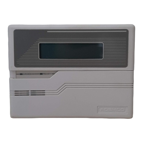
ADEMCO Vista 4130XT User manual

Other ADEMCO Security System manuals

ADEMCO Alert II User manual

ADEMCO

ADEMCO Alert II User manual

ADEMCO 4080 User manual

ADEMCO

ADEMCO 4080 User manual

ADEMCO Vista-10SEa User manual

ADEMCO

ADEMCO Vista-10SEa User manual

ADEMCO VISTA-50PUL User manual

ADEMCO

ADEMCO VISTA-50PUL User manual

ADEMCO VSTA-20se User manual

ADEMCO

ADEMCO VSTA-20se User manual

ADEMCO 4110DL User manual

ADEMCO

ADEMCO 4110DL User manual

ADEMCO ALERT III User manual

ADEMCO

ADEMCO ALERT III User manual

ADEMCO 4140XMPT2 User manual

ADEMCO

ADEMCO 4140XMPT2 User manual

ADEMCO Ademco VISTA-40 User manual

ADEMCO

ADEMCO Ademco VISTA-40 User manual

ADEMCO Alarm System Instruction manual

ADEMCO

ADEMCO Alarm System Instruction manual

ADEMCO via30+ User manual

ADEMCO

ADEMCO via30+ User manual

ADEMCO LYNXR24 User manual

ADEMCO

ADEMCO LYNXR24 User manual

ADEMCO Q16 Installation instructions

ADEMCO

ADEMCO Q16 Installation instructions

ADEMCO 4110 User manual

ADEMCO

ADEMCO 4110 User manual

ADEMCO 4110 User manual

ADEMCO

ADEMCO 4110 User manual

ADEMCO galaxy 8 User manual

ADEMCO

ADEMCO galaxy 8 User manual

ADEMCO Security System VISTA-10SE Operating instructions

ADEMCO

ADEMCO Security System VISTA-10SE Operating instructions

ADEMCO VIA-30PSE Operating instructions

ADEMCO

ADEMCO VIA-30PSE Operating instructions

ADEMCO VISTA-20SE Owner's manual

ADEMCO

ADEMCO VISTA-20SE Owner's manual

ADEMCO Vista-10SEa Assembly instructions

ADEMCO

ADEMCO Vista-10SEa Assembly instructions

ADEMCO 4110DL User manual

ADEMCO

ADEMCO 4110DL User manual

ADEMCO VISTA-128B User manual

ADEMCO

ADEMCO VISTA-128B User manual

ADEMCO VISTA-20P Series User manual

ADEMCO

ADEMCO VISTA-20P Series User manual

ADEMCO Security System VISTA-10SE User manual

ADEMCO

ADEMCO Security System VISTA-10SE User manual

Popular Security System manuals by other brands

Polon-Alfa 4000 Installation and maintenance manual

Polon-Alfa

Polon-Alfa 4000 Installation and maintenance manual

Nexcom NViS 14162 Series user manual

Nexcom

Nexcom NViS 14162 Series user manual

Eminent EM8670 Quick install

Eminent

Eminent EM8670 Quick install

urmet domus alpha 1060 INSTALLATION AND USE BOOKLET

urmet domus

urmet domus alpha 1060 INSTALLATION AND USE BOOKLET

SmartPool YardGuard YG03 manual

SmartPool

SmartPool YardGuard YG03 manual

DSC PC5964 Mounting instructions

DSC

DSC PC5964 Mounting instructions

Secure USAB-1 operating instructions

Secure

Secure USAB-1 operating instructions

B&B 480 SERIES Operation & maintenance manual

B&B

B&B 480 SERIES Operation & maintenance manual

Inner Range Concept 2000 user manual

Inner Range

Inner Range Concept 2000 user manual

Johnson Controls PENN Connected PC10 Install and Commissioning Guide

Johnson Controls

Johnson Controls PENN Connected PC10 Install and Commissioning Guide

Aeotec Siren Gen5 quick start guide

Aeotec

Aeotec Siren Gen5 quick start guide

Swann SW-P-MC2 Specifications

Swann

Swann SW-P-MC2 Specifications

Ecolink Siren+Chime user manual

Ecolink

Ecolink Siren+Chime user manual

EDM Solution 6+6 Wireless-AE installation manual

EDM

EDM Solution 6+6 Wireless-AE installation manual

Siren LED GSM operating manual

Siren

Siren LED GSM operating manual

Detection Systems 7090i Installation and programming manual

Detection Systems

Detection Systems 7090i Installation and programming manual

FRIEDLAND MA10 Installation and operating instructions

FRIEDLAND

FRIEDLAND MA10 Installation and operating instructions

Se-Kure Controls MicroMini SK-4841 instructions

Se-Kure Controls

Se-Kure Controls MicroMini SK-4841 instructions

manuals.online logo
manuals.online logoBrands
  • About & Mission
  • Contact us
  • Privacy Policy
  • Terms and Conditions

Copyright 2025 Manuals.Online. All Rights Reserved.

INSTALLATION INSTRUCTIONS
ViSTA
SECURITY SYSTEM
No. 4130XT
10/88
Previous Menu
General Information ...............................................................................4
Remote Programming and Control ....................................................................5
Zone Types Available for Selection ...................................................................7
Functional Description of Zone Types .................................................................8
Zone Expansion .................................................................................12
4-Digit Security Codes ............................................................,..............,12
Wiring Connections ...............................................................................16
Remote Keyswitch Operation and Wiring ............................................................18
Optional Remote Keypad Connection (4131/4147) . . . . . . . . . . . . . . . . . . . . . . . . . . . . . . . . . . . . . . . . . . . . . . . . . ...18
Optional Remote Console Connection (4137/4157) . . . . . . . . . . . . . . . . . . . . . . . . ...........................19
installing the Digital Communication Interface Board .....................................................20
installation of No. 4152LMand Wiring to No 4208 .......................................................21
Mounting the 4130XT Control. ......................................................................22
Surface Mounting ................................,.............................,....,. ........,22
Flush Wall Mounting ............................................................................24
Programming the Security Control ...................................................................28
Factory Preset Values ...........................................................................29
Specific Address Programming Instructions ..........................................................40
Testing the System ...............................................................................70
Turning the System Overto the User .................................................................71
To the installer ..................................................................................71
Recalling Alarm and Trouble Messages ...............................................................71
Replacing Fuses on 4130XT Circuit Board .............................................................72
Replacement Parts ...............................................................................73
Optional Accessories .............................................................................73
FCC Statement ..................................................................................74
Specifications .................................................................... 75
4130XTSecurity Control ..... ,. . . . . . . . . . . . . .
....................................................................75
4171XT Digital Communication Interface Board .......................................................75
4137 Remote Console .............................. . . . . . . . . . . . . . . . . . . . . . . . . . . . . . . . . . . . . . . . . . . . . .75
4157 Remote Console . . . . . . . . . . . . . . . . . . . . . . . . . . . . . . . . . . . . . . . . . . . . . . . . . . . . . . . . . . . . . . . . . . . . . . . . ...76
4131/4147RemoteKeypad... ...................................................................76
4152LM Loop Module ...........................................................................76
42088-Zone Expander ..........................................................................77
Appendix A, Cabinet Mounting.. ....................................................................77
The Limitations ofthisAlarm System .................................................................80
Limited Warranty . . . . . . . . . . . . . . . . . . . . . . . . . . . . . . . . . . . . . . . . . . . . . . . . . . . . . . . . . . . . . . . . . . . . . . . . . . . . . . . . .82
Diagrams
Diagram l, Summary of Connections .................................................................I7
Diagram 2, 24-Pin Connector with Flying Leads
(4130XT Field Wiring interface) ............................................................18
Diagram 3. Keyswitch Wiring... . . . . . . . . . . . . . . . . . . . . . . . . . . . . . . . . . . . . . . . . . . . . . . . . . . . . . . . . . . . . . . . . . . . . 19
Diagram 4. Installing the Digital Communication
Interface Board . . . . . . . . . . . . . . . . . . . . . . . . ,! . . . . . . . . . . . . . . . . . . . . . . . . . . . . . . . . . . . . . . . . . . . . . . .20
Diagram 5. 4152LMlnstallation and Wiring to 4208 ......................................................21
Diagram 6.4130XT Connector Interfacing and
4171XT Wiring Connections . . . . . . . . . . . . . . . . . . . . . . . . . . . . . . . . . . . . . . . . . . . . . . . . . . . . . . . . . . . . ...23
Diagram 7.1nserting Nameplate . . . . . . ...............................................................24
Diagram 8. Wall Preparation for Flush Mounting . . . . . . . . . . . . . . . . . . . . . . . . . . . . . . . . . . . . . . . . . . . . . . . . . . . . . . . . . 26
Diagram 9. Flush Mounting the4130XT/4137/4147 . . . . . . . . . . . . . . . . . . . . . . . . . . . . . . . . . . . . . . . . . . . . . . . . . . . . .27
Diagram 10. Removing Main Circuit Board for Fuse Replacement ..........................................72
Template for Mounting the4130XT/4137/41 47 (provided on separate sheet)
The VISTA 4130XT ISamicroprocessor-based security control which
provides up to 9wired zones in the basic product, with expansion to an
additional wired zones when connected toa2-wire zone expansion bus
driven bytheoptional No.4152LM Loop Module Thesecurity control is
housed in awall-mounled plastlc enclosure measurmg only 8.4” (21.3
cm) wide x4.75 (12 cm) high x1.1” (2.8 cm) deep, and is equipped with
amultifunction 12-key digital keypad, amultipurpose LCD English lan-
guage display and a built-in 85 db piezoelectric sounder that meets UL
requirements as an alarm sounder (an external sounder IStherefore
optional). ConnectIons to the security ,control are made via a24-pm plug-
in connector equipped with flylng leads which interface to the wired
loops, plug-in DC Power Pack, back-up battery, optional external alarm
sounder, etc.
The security control is programmable from its own keypad or from a
4137 or 4157 remote console (optional), and can also be programmed
locally from the 699 Programmer (using a695-30XT cartridge).
Programmed options to eslablish specific alarm and reporting features
are stored in electrically erasable, non-volatile EEPROM memory. This
means that the unit can be reprogrammed many times (unlike umts
equipped with PROMS) and that information which has been
programmed will not be lost in the event of acomplete loss of power. For
installer convenience, the control is factory-programmed to aset of
values that is designed to meet the needs of many installations. However,
these can be altered by the installer to suit the specific needs of a
particular installation or installation company, following the instructions
provided in the programming section of this manual (factory-programmed
values are also shown in this section).
Aplug-in Communication Interface board (4171 XT) is required with this
system and provides communication capability (central station reporting,
etc,) over existing telephone lines as well as zone expansion
connections.
An optional, economical, remote keypad (4131 or 4147) can be used for
arming, dmarmmg, etc., from aremote indoor location within the pro-
tected premises, This unit is acompact 12-button keypad with two sys-
iem status indicators (LEDs) and a built-in p!ezoelectric sounder that
provides warning and alarm sounds. Requires a10-wire connecbon to
the control.
An optional remote console (4157) will provide system status indications
and WIIIperm[t virtually all system control functions from its keypad. The
console will also provide visible and audible indications of troubles and
alarms by means of LEDs and numeric (zone number) display and bullt-
In piezoelectric sounder. Requires only a4-wire connection to the
control
An optional remote console (4137) is available which is identical to the
4130XT control in Its appearance, system operation, LCD displays, and
loud piezoelectric alarm sounder. Requires only a4-wire connection to
the mam control.
Acomplete list of optional accessories will be found masection toward
the end of this manual under the heading “Optional Accessories” (see
Index).
Zone Characteristics
Zone 1:
zones 2-a
Zone 9
Programmable Zone, may be used as EOLR superwsed Fire
Zone (supports 2-wire Smoke Detectors), or may be used as
anon-fire zone with N C contacts only, 350-500 msec
response.
Programmable Zones, EOLR supervised, 350-500 msec
response
Programmable Zone, NC. contacts only, fast 10-15 msec
response.
Back-up 12V DC Battery DC Power Pack
Mounted externally. Aspectal backbox (4132) is available for mounting Plug-in Power Pack (DC power converter). Plugs into unstitched 2-prong
the battery in the wall behind the Control. Rechargeable 12-volt, 1.2 AH 110 volt AC outlet providing 24-hour serwce. Power Pack (1350) supplies
Lead Acid. unregulated 18V DC output (700 mA max) for powering the Control.
The No. 4130XT allows the installer to call it using switched network
phone lines so that the control/communicator can be remotely
programmed and/or commanded from aNo 699MD Intelligent
Programmer or an IBM compatible Personal Computer (PC). See Note 2
under Remote Capabilities in this section.
Accessing of the No. 4130XT from aremote location is protected against
compromise by someone attempting to defeat the system, using 4levels
of security protection:
1
2
3
Security Code Handshake: An 8digtt Central Station ID code must
be matched between the No. 4130XT and the Central Station.
Hang-up and call back: Calling the No. 4130XT does not directly
allow programming, as asuccessful handshake merely results in the
No. 4130XT breaking the phone line connection and then calling back
the (internally stored) central station service phone number’.
Data Encrwtion: Data passed between the central station and the
No, 4130X~”is encrypted for security so that it is very difficult for afor-
eign device tapped into the phone line to take over communication
and substitute system compromising Information.
*NOTE: In situations where aservice person is on stte and the system is
installed inside aPABX, it is possible to initiate adownload from
the protected premises by keying [installer or master security
code] +[#] +[1].
4Central Station Advisory Note: Any condition that causes the system
to initiate acall back to atelephone number from which it can be
reprogrammed or commanded (in fact, even for alocal reprogramming
of the EEPROM) causes aunique report to be sent to the central sta-
tion’s alarm Ioggmg digital receiver.
Equipment Required
At the premises
The No. 4130XT must be used with its No. 4171 XT Communication Inter-
face board if remote programming and/or control is desired.
At the central station (or the installer’s office/home):
●ANo. 699MD Intelligent Programmer that incorporates an internal
modem and a No. 695-30XT Program Cartridge.
OR
cAn IBM PC compatible computer, aModem (check with Ademco Factory
Technical Support for the specific brand and model to be used), No.4130PC
Downloading Software Diskette, and appropriate interconnecting cables.
Remote Capabilities (See Note 2)
Programming:
All programming functions accessible from the unit’s keypad or via local
No 693 direct programming.
Commanding:
There are two types ot commands that can be issued to the system:
1. Control Commands —
-To Arm the System in the Away Mode* (’)
-To Disarm the System* (t)
-To Bypass aZone
-To Force the System to Accept aNew Program Download
-To Shut DowrI Communication (dialer) Functions (non-payment of
monitormg fees man owner’s system)
-To Shut Down all Security System Functions (non-payment for a
leased system)
-To Inhibit Local Keypad Programming (prevents takeover of your
accounts)
2. Status Commands —
-To Cause the System to Upload aCopy of its Resident Program to
the central station
To Read System Status:
Arming Status
Ready Status and Current Faults
Presence of Alarms (pastor present)
Presence of Troubles (past or present)
AC Power Status
Bypass Status and Current Bypasses
*NOTES 1.If the system is programmed for open/close reporting by
user, User #7 will be reported.
2. After the4130XT and the 699 or PC have established valid
communication, each 4157 console displays an ‘OC’ sig-
nifying that It ISbusy (occupied). Also, the 4130XT is not
responding to faults in its zones. The 4130XT will resume
the normal security tunctlons (mcludmg responding to faults
that look place during the downloading) after it is com-
manded to hang up See the 4130PC or 695-30XT instruc-
tions for details.
The detailed operation of the functions described below IScovered mthe
Installation Instructions for the No. 695-30XT Program Cartridge and for
the 4130PC Download Software Diskette.
To Read List of Faulted Sensors
To Read List of Bypassed Sensors
-To Read 10 Day Alarm History Log
-To Read 10 Day Trouble History Log
-To Read List of Sensors Currently mAlarm
-To Read List of Sensors Currently in Trouble
Remote Communication Specifications:
.Program Download Time —1minute for acomplete program
.Typical Total Time Including Call Up/Call-Back —3-4 minutes
Remote Command/Programming Advisory Notes:
●Alarm and Trouble Reporiing are disabled during the time that the SYS-
tem and the central station are linked to each other for the described
functions, following avalid exchange of codes.
●Keypad entries are ignored during the same time interval cited above.
.Should an alarm transpire during the remote program/control interval,
the system would not respond to the alarm condition untd the remote
mode was ended. The local zones and the Nos. 4190WH, 4192,
4194WH, 4196, and 4208 all store their fault conditions until they are
read by the Control, As such, alarm conditions from the local and
expansion zones would not be missed, only delayed.
.Acopy of the program downloaded may be produced from either the
No, 699 Intelligent Programmer or the IBM PC compatible computer,
using those products’ internal report generators, when an optional prin-
ter is connected.
For each zone used, one of the following zone types must be selected: 7
1. Entry/Exit Burglary (Delay #1). Assigned to sensors on doors
through which entry and exit WIIInormally take place when the sys-
tem Earmed. B
2. Entry/Exit Burglary (Delay #2). May be set for different delay than
above. For use with sensors on overhead garage doors, etc., where
longer delay wneeded to reach the keypad in the main portion of the
house or building, and more delay is needed to exit the premises.
3. Perimeter Burglary. Normally assigned to all sensors on exterior
doors and windows requiring mslant alarm. 9
4lntetior, Follower. Delay edalarm only ifthe Entry /Exit zone is 10
faulted first otherwise, produces an instant alarm. Assigned to zone
covering an area such as afoyer or lobby through which one must
pass upon entry toreach thekeypad todisarm the system Designed
to provide instant intrusion alarm in the event an intruder hides on the
premrses prior to the system being armed or gatns access to the
premises through an unprotected area.
5. Trouble by Day/Alarm by night. Can be assigned to azone which
contains afoil-protected door or window (such as in astore), or to a
zone covering a“sensitwe” area such as astock room, drug supply
room, etc., or other controlled access area where immediate
notification of an entry Mdesired. During the disarmed state (day), the
system will prowde latched Control/Console annunciation (and cen-
tral station report, if desired) of openings or troubles (such as sensor
malfunctions or foil breaks), During the armed state (night), violations
will initiate an alarm.
6. 24-hour Silent Alarm. This type generally assigned to azone con-
taining an Emergency button that is designed to initiate an alarm
report to the Central Station, but which produces no local displays or
alarm sounds.
24-hour Audible Alarm. This type also assigned to azone contain-
ing an Emergency button, but which will initiate an audible alarm in
addition to an alarm report to the Central Station.
24-hour Auxiliary Alarm (Control internal sounder only). This type
assigned to azone containing abutton for use in personal emer-
gencies, or to azone containing monitoring devices such as water
sensors, temperature sensors, etc Designed to initiate an alarm
report to the Central Station and also provide Control/Console alarm
sounds and alarm displays.
Supervised Fire (alarm on short/trouble on open).
Interior that always has Entry/Exit Delay #1 (except that Entry
delay is suppressed in the INSTANT mode). This type Iypicaliy
assigned to an interior zone containing aPIR that covers an area
through which the user must pass to reach the Control for disarming
purposes (whether inside or first entering). Ideal for an area such as
an apartment entrance foyer in which akeypad is located.
The following is adescription of the various zone types available which
must be selected for each physical zone. You may w!sh to use Table Aat
the end of this description to record your selections.
Type 1. BURGLARY ENTRY/EXIT (DELAY #l): This zone type is not
enabled after armmg untd termination of the (EEPROM defined)
Exit delay #l Upon entry, the Control WIIIsimply emit three
short beeps as awarning th~l the system must be dtsarmed
(for added security, this system does not emit wammg s{gnals
throughout the Entry delay period). If Code +OFF is not entered
before term} nation of the (EEPROM defined) Entry delay #1, an
alarm will be imtlaled at the buill-in sounder, if program
enabled, and an external alarm and latched LCD dmplay. If a
Commurucatlon board is used, asystem-wide EEPROM
defined number of alarm reports for this zone will be allowed to be
transmitted (swinger suppression) In one armed period.
Restorals will be sent when the zone is restored for atime
greater than its physical response hme (less than 1second).
Dur(ng the disarmed state, afaulted zone wdl result !n aNOT
READY display. Subsequent depression of the READY key wdl
cause all the faulted zones to be sequentially displayed. No
communicator reports will be imbaled.
TVDt2 2. BURGLARY ENTRY/EXIT (DELAY #2k This zone tvDe is not
.. enabled after armmg until ter’minabon of \he (EEPROM’defined)
Exit delay #2 Upon entry, the Control will simply emit three
short beeps as awarning that the system must be disarmed
(for added security, this system does not emit warning signals
throughout the Entry delay period) If Code +OFF is not entered
before termination of the (EEPROM defined) Entry delay #2, an
alarm will be imtiated at the budt-rn sounder, if program
enabled, and an external alarm and latched LCD display. If a
Type 3,
Type 4.
Communication board is used, asystem-wide EEPROM
defined number of alarm reports for this zone WN be allowed to
be transmitted (swinger suppression) in one armed interval.
Restorals wtll be sent when the zone ts restored for attme
greater than its physical response time (less than 1second),
During the disarmed state, afaulted zone will result in aNOT
READY display Subsequent depression of the READY key WN
cause all the faulted zones to be sequentially displayed No
communicator reports WIIIbe initiated.
BURGLARY PERIMETER: While the System is armed, a
faulted zone w(II initiate an alarm at the built-in sounder, if
program enabled, and an external alarm, alatched LCD
dmplay, and a (EEPROM selected) communicator report.
Depression of any key will silence the Control’s local alarm
sounder for 10 seconds. Asystem-wide EEPROM defmed
number of alarm reports for this zone will be allowed to be
transmitted (swinger suppression] by the commumcator mone
armed period. The communicator will transmit arestoral mes-
sage when the zone mrestored for atime greater than ils physi-
cal response time (less than 1second).
During the disarmed slate, afaulted zone will result in aNOT
READY display, Subsequent depression of the READY key will
cause all the faulted zones to be sequentially displayed. No
commurlicator reports will be initiated.
BURGLARY INTERIOR, FOLLOWER: This zone will always
have Exit Delay #l The zone has an Entry Delay if preceded
by afault in an Entry/Exit zone (type #1 or #2) If not preceded
by an Entry/Exit zone fault, an Immediate audible local (Con-
trol) and external alarm, latched display, and a (EEPROM
selected) commumcator report are mltlated. Depressing any
key at the Control will silence the Control sounder for 10
r- seconds Asystem-wide EEPROM defined number of alarm
reports for this zone will be allowed to retransmitted (swinger sup-
pression) by the communicator in one armed period, The
communicator will transmit arestoral message when the zone
is restored for atime greater than its physical response time
(less than 1second).
During the disarmed state, afaulted zone will result in aNOT
READY dwplay. Subsequent depression of the READY key will
cause all the faylted zones to be sequentially displayed, No
communicator reporls will be initiated,
Type 5. BURGLARY PERIMETER, TROUBLE BY DAY/ALARM BY
NIGHT: During the disarmed state (day), faulting the zone will
initiate a“trouble” display and a latched sounder (beeping).
The Control will beep rapidly along with alatched display of the
faulted zone and the word CHECK, Pressing any key will
silence the beeping for 10 seconds. Code +OFF will silence
the beeping but will only clear the display of azone that had
the fault condition removed.
If aCommunication board is used, each trouble will result in a
“trouble” report (if programmed). Atrouble restoral message
will be sent as each zone is restored to normal condition. The
maximum number of trouble reports per armed period will be
limited by the system-wide EEPROM number of alarm reports
option (swinger suppression).
During the armed state (night), the local (Control) and external
(if used) alarm sounder will activate and the communicator will
report alarms. Asystem-wide EEPROM defined number of
alarm reports for this zone will be allowed to be transmitted in
one armed period, Restorals will be sent when the zone is re-
stored for atime greater than its physical response time (less
than 1second).
Type 6. 24-HOUR SILENT ZONE Sensors assigned to this zone,
when faulted, will initiate acommunicator report. There will be
no local displays or alarm sounds. Upon keying Code plus OFF,
there will be a memory indication of the faulted zone.
Asystem-wide EEPROM defined number of alarm reports for
this zone will be allowed to be transmitted (swinger suppres-
sion) by the communicator until an OFF sequence is per-
formed. The communicator will transmit arestoral message
when the zone is restored for atime greater than its physical
response time (less than 1second).
During the disarmed state, NOT READY will be displayed if a
sensor is faulted. The burglary portion of the system cannot be
armed if this zone is faulted. An OFF sequence (code plus OFF)
should be performed prior to arming the system or viewing the
faulted zones via the *key,
Type 7. 24-HOUR AUDIBLE ZONE: Faulting azone of this type will
initiate aloud audible alarm externally and at the Control, an
LCD display, and a (EEPROM selected) communicator report.
Pressing any key will silence the Control sounder for 10
seconds. Keying Code plus OFF will permanently silence the
alarm. Asystem-wide EEPROM defined number of alarm
reports for this zone will be allowed to be transmitted (swinger
suppression) by the communicator until an OFF sequence is
performed The communicator will transmit arestoral message
when the zone is restored for atime greater than its physical
response time (less than 1second).
Type 8. 24-HOUR AUXILIARY ZONE Faulting azone of this type will
initiate asteady alarm sound at the Control, an
ALARM display, and a (EEPROM selected) communicator
report. Pressing any key will silence the Control sounder for 10
seconds. Keying Code plus OFF will permanently silence the
alarm. Asystem-wide EEPROM dehned number of alarm
reports for this zone will be allowed 10 be transmitted (swinger
suppression) by the communicator untd an OFF sequence is
performed. The communicator will transmit arestoral message
when the zone is restored for atime greater than its physical
response time (less than 1second).
Type 9. FIRE ZONE: Opens in this zone will result in “troubles”. Shorts
will result in alarms. Note: Zone 1will support 2-wire Smoke
Detectors (using the EOL resistor configuration): Zones 2
through 8can be used for heat detectors and pull stations and
for 4-wire Smoke Detectors with external (manual) power inter-
rupt; Zone 9cannot be used for Fire.
Fire zones may not be bypassed. Afire zone mtrouble will not
prevent the burglary system from being armed in any mode
Asystem-wide EEPROM defined number of alarm reports for
this zone will be allowed to be transmitted (swinger suppres-
sion) by the communicator in one armed period. The communi-
cator will transmit arestoral message when the zone
is restored (less than 1second).
Type 10. INTERIOR DELAY ZONE: This type of zone will always have
an Entry delay #l and Exit delay HI. Thw zone ISnot enabled
after armmg until termination of the (EEPROM defined) Exit
delay #1. If this zone Efaulted, three beeps will be emitted by
the Control. If Code +OFF Enot entered before termination of
the (EEPROM defined) Entry delay #1, an alarm will be mitlated.
Asystem-wide EEPROM defined number of alarm reports for
this zone WIIIbe allowed 10 be transmitted (swinger suppres-
sion) by the communicator in one armed period. The commun-
icator will transmit arestoral message when the zone ISre-
stored for atime greater than its physical response time (less
than 1second).
During the disarmed state, afaulted contact WIIIresult mNOT
READY being displayed. Subsequent depression of the READY
key will cause all the faulted zones to be sequentially displayed,
but no commurucator reports will be initiated.