ADENDORFF ML392 User manual

·
COMBINED
10”& 12” PLANER & THICKNESSER
Model No. ML392
ML393
ML393Q
INSTRUCTION MANUAL
Carefully read this instruction manual before operating machine.

1
INDEX OF CONTENTS
TABLE OF CONTENTS
PAGE 1
GERNERAL SAFETY RULES
PAGE 1-3
RECOMMENDATIONS
PAGE 3
RECEPTION HANDLING
PAGE 3-4
TRANSPORTAND STOCKING
PAGE 4
PLACING THE MACHINE ON THE FLOOR
PAGE 4
INSTALLATIONG
PAGE 4
PREPERATION OF THE MACHINE
PAGE 5
WORKING CONTITIONS
PAGE 5
ELECTRICAL CONNECTION
PAGE 5
GENERAL INFORMATION
PAGE 6
TECHNICAL DATA
PAGE 7
NOISE LEVELS
PAGE 7
EXHAUSTING SYSTEM
PAGE 8
THE ELETRICAL DIAGRAM
PAGE 8
WORKING OPERATIONS
PAGE 9
ADJUSTMENT OF THICKNESSER
PAGE 11
TOOLS
PAGE 12
MAINTENANCE
PAGE 13
REPAIRS
PAGE 14
PARTS DIAGRAM
PAGE 15
PARTS LIST
PAGE 19
GENERAL SAFETY RULES
NOTE: Read all these instructions before attempting to operate this product. Save these
instructions for future reference.
1. Keep work areas clear. Cluttered areas and benches invite injuries.
2. Consider work area environment. Do not expose tools to rain. Do not use tools in damp or
wet locations. Keep work areas well lit. Do not use tools in the presence of flammable liquids or
greases.
3. Guard against electric shock. Avoid body contact with earthed or grounded surfaces.
4. Keep other people away. Do not let other persons, especially children, not involved in the
work touch of the tool or the extension lead and keep them away from the work area.
5. Store idle tools. When not in use, tools should be stored in a dry locked-up place, out of reach
of children.
6. Do not force the tool. It will do the job better and safer at the rate for which it was intended.
7. Use the right tool. Do not force small tools to do the job of a heavy-duty tool. Do not use tools
for purposes not intended, for example, do not use circular saws to cut tree limbs or logs.
8. Dress properly. Do not wear loose clothing or jewelry; they can be caught in moving parts.
Non-skid footwear is recommended when working outdoors. Wear protective hair covering to
contain long hair.
9. Use protective equipment. Use safety glasses. Use face or dust mask if cutting operations
create dust.

2
10. Connect dust extraction equipment. If devices are provided for the connection of dust
extraction and collection equipment, ensure these are connected and properly used.
11. Do not abuse the cable. Never pull the power cable to disconnect it from the socket. Keep
the cable from the socket. Keep the cable away from heat, oil and sharp edge.
12. Secure work. If possible use clamps or a vice to hold the work. It is safer than using your
hand.
13. Do not over reach. Keep proper footing and balance at all times.
14. Maintain tools with care. Keep cutting tools sharp and clean for better and safer
performance. Follow instructions for lubricating and changing accessories. Inspect power cables
periodically and if damaged have them replaced by an authorized service facility. Inspect
extension cables periodically and replace if damaged. Keep handles dry, clean and free from oil
and grease.
15. Disconnect tools. When not in use, before servicing and when changing accessories such
as blades, bits, cutters, disconnect tools from the power supply.
16. Remove adjusting keys and wrenches. Form the habit of checking to see that keys and
adjusting wrenches are removed from the tool before turning it on.
17. Avoid unintentional starting. Ensure switch is in “OFF” position when plugging in.
18. Use outdoor extension leads intended for outdoor use and so marked.
19. Stay alert. Watch what you are doing, use common sense and do not operate the tool when
you are tired.
20. Check damaged parts. Before further use of the tools, it should be carefully checked to
determine that it operates properly and perform its intended functions. Check the alignment of
moving parts, binding of moving parts, breakage of parts, mounting and any other conditions
that may affect its operation. A guard or other part that is damaged should be properly repaired
or replaced by an authorized service center unless otherwise indicated in this instruction manual.
Do not use the tool if the switch does not turn on and off.
21. Warning! The use of any accessory or attachment other than one recommended in this
instruction manual may present a risk of personal injury.
Have your tool repaired by a qualified person. This electric tool complies with the relevant safety
rules. Repairs should only be carried out by qualified technicians by using original spare parts,
otherwise this may result in considerable danger to the user.
22. Have your tool repaired by a qualified person. This electric tool complies with the relevant
safety rules. Repairs should only be carried out by qualified technicians using original spare
parts, otherwise it may result in danger to the operator.
23. Never use the machine if the appropriate guard is not in place and correctly adjusted.
24. Do not use knives that are blunt as this increases the danger of kickback of workpieces.
25. Any portion of the cutterblock not being used for planing shall be guarded.
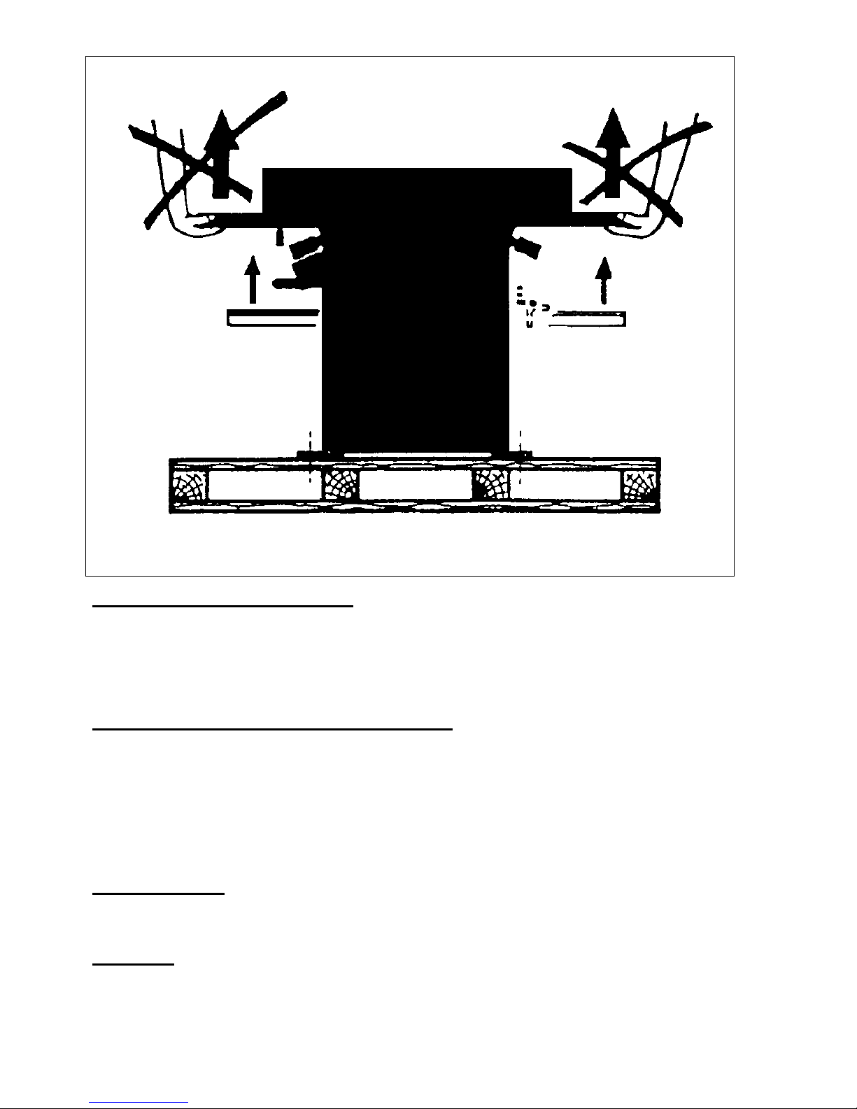
26. When planing narrow short workpieces, a push stick should be used.
27. When planing narrow workpieces, additional measures, such as the use of horizontal
pressure devices and spring-loaded guards, may be necessary to ensure safe working.
28. Do not use the machine to cut rebate.
29. Before starting the machine carefully read the instruction manual to avoid any risks of
personal injury.
30. The effectiveness of the device for the prevention of kickback and the feed roller should be
regularly inspected to ensure safe operation.
31. Tool equipped with chip collection and extraction hoods shall be connected to the
dust-and-collecting device.

3
RECOMMENDATIONS
No one must work on a wood machine without first receiving sufficient training concerning the
type of work and without being informed of the risks, the precautions to observe and operating
instructions for the guards and compulsory safety devices.
This machine is designed for wood derivatives. It should not be used for other materials.
-Before use we recommend that you carefully read through this manual and that you respect
all instructions contained in it in order to achieve the best results from your machine and to
work in complete safety.
-In order to ensure that all safety measures taken into consideration during the design of this
machine are met any modification of the machine by the user is forbidden.
-Connection to a sawdust or chipping suction aspirator is obligatory to satisfy all the
hygiene/safety conditions and to ensure the correct operation of this machine.
-You are strongly recommended to wear protective glasses while using this machine.
-Residual risk
As with all wood-working machines with manual adjusting, there is always a risk, even when
guards are in place and correctly adjusted, of getting close to tools at a working height which
corresponds to the thickness of the wood.
It is essential, therefore, that hands are kept well away from the dangerous areas and that
the end of pass thruster is used.
RECEPTION HANDLING
The machine is delivered fully assembled. When handling with the machine use the certified
lifting equipment and safe instruments. The best handling can be done with transport pallet and
high lift truck. For lifting the operator can use steel wire rope seal with min diameter 5mm.
Before placing the machine on working place, the operator has to consider how large pieces of
material, which can be cut in the given room.
Safe work with the machine requires enough space around the machine. When you are sure
that the placing responds with your idea, flush the machine with max clearance 1mm/1000mm
and screw it on the floor. In any cases the operator has to level (flush) the machine in the right
way by help of four adjusting screws (placed in adjustable legs). Do not assemble parts (which
were disassembled) before the operator has read the whole instruction manuals and has known
the machine well.
Put the lengthwise rule on the guide way and adjust the length stop and secure. Clamp the
sliding table on the bars (guide way) or the support of the run-out arm and secure with the small
hand crank. Put the angular rule on the sliding table and secure.
Enclosed the operator will find the instruction manual and wrenches necessary.
Check the condition of the machine and the number of packages mentioned on the delivery note.
If necessary, make the usual reverse to the carrier.
WARNING! If reverse are made they must be made on receipt of the goods. Late claims will not
be considered.
For delivery, the machine is mounted on the wooden crate with wood blocking on the bottom of
the crate.

4
TRANSPORT AND STOCKING
During the transport and stocking it is necessary to protect the machine from excessive
vibrations and excessive humidity. The machine can be stocked under the roof with air
temperature from –250C to 550C.
PLACING THE MACHINE ON THE FLOOR
Remove the metal sheet clamping.
Remove the attachments fixing the machine to the crate (screws and bolts)
Clear a sufficient large area round the machine.
Raise the machine slightly and fit two planks under the feet. Use planks which are long enough
to act as ramps down to the floor. Pull the machine making sure that it stays on the planks.
Once the machine is clear of the crate it will tip.
INSTALLATION
To guarantee corrected alignment of the working surfaces and prepare a stable, level,
concrete floor.
WARNING! When handling, take care to avoid shocks or large forces which could cause
damage or put the machine out of adjustment.

5
PREPARATION OF THE MACHINE
The machine unpainted parts are protected with a factory-applied ultra-fine oily film. It is not
necessary to remove it before using the machine. However, if you wish you can remove it, use a
cloth soaked spirit. Wipe and clean and then apply a sliding agent (Sliber-gleit, Molycote, etc.).
WORKING CONDITIONS
The machine is intended for work under the roof if the following conditions are fulfilled.
Air temperature: from 50C to 400C, relative humidity: from 30% to 95% non-condensing, altitude
above sea level: max 1000m.
The machine must be used as a stationary tool.
ELECTRICAL CONNECTION
WARNING! Before connection to the mains, check that the mains voltage corresponds with the
characteristics of the machine supplied.
Use a 1.5 mm2 (min.) supply cable with strengthened insulation, (e.g.HO7). If the length of the
cable from the meter to the machine exceeds 10 meters, use 2.5mm2 (min) cable. The internal
connections (motor, switch, coil, etc.) are factory wired.
SINGLE PHASE 230V CONNECTION: This connection should be made with a 3 core cable
and a standard 16A two pole + earth plug. Two wires are provided for the supply (L1, L2) and
the third (yellow/green) must be connected to the earth.
THREE PHASE 380V CONNECTION: This connection should be made with a 4 core cable and

6
a standard 16A three pole + earth plug. Three wires are provided for the supply (L1, L2, L3) and
the fourth (yellow/green) must be connected to the earth terminal.
IMPORTANT: Three phase connection necessaries checking the correct direction of rotation of
the motor shaft to avoid any problems with the belt drives.
It is essential t start the motor for the first time without a drive belt. If necessary, reverse the
position of 2 of the 3 supply wires from the mains to obtain the correct rotation for the normal
cutting direction.
In the event of a change to the 3 phase supply (variety of supply points, more than one socket in
a basement, etc.), it is essential t repeat this check on the direction of rotation as explained
above.
NOTE: For a temperature below 10 0C we recommend warning up the motor by letting it run
off-load on any function.
WARNING: Before adjusting or exchanging knives and any maintenance or repairs disconnect
the machine from the mains. If the operator is standing at the side of the machine against the
backstop, the main cutterblock has to be rotated clockwise (consequently to the right). It is
possible to change the rotation direction by exchanging (switch-over) wires (black and/or brown)
for three-phase motors.
ATTENTION: The machine is injury menaces with the contrary rotation of the cutter block.
Switch on the machine only for a while to find out the right direction of rotating (if possible –
without tool).
The machine is also equipped with brake motor, which is able to stop the machine within
required time. However, this brake motor works only when the machine is switched off by
pushing red button or emergency stop cover.
When the brake does not work properly, it is forbidden to work with the machine.
The switch cannot be turned on until the machine is connected to the mains. The switch is
turned off automatically by way of neutral protection with outage, it means that it is necessary to
switch on the machine again after restoring of the current. Should the machine is switched off
frequently in sequence (twice of threefold), check up the machine (the motor functions, the blunt
tool, etc.).
The machine can be secured with a padlock placed on the switch which protects the machine
from unauthorized usage.
NOTE: If the protection system is not repositioned completely, feedback circuit will restrict the
motor starting.
GENERAL INFORMATION
This combination-designed machine allows the operator to perform the following operations
consecutively: surface planing, thicknessing.
Surface planing: Adjustable infeed table, max. cut depth 5mm.
Thicknessing: Table height adjustable by hand wheel and button position locking –Chip
discharge case for correct chip discharge –Pass limiter –Extraction nozzle –Anti-throw-out
pawl.

7
TECHNICAL DATA
Model No.
10”(ML392)
12”(ML393Q)
12”(ML393)
Planer tables
1085x250mm
1285x310mm
1600x310mm
Thicknesser tables
600x248mm
600x310mm
750x310mm
Cutterblock diameter
75mm
75mm
95mm
Cutterblock speed
4000rpm
4000rpm
4000rpm
Fence tilt
0-450
0-450
0-450
Dust chute
100mm
100mm
100mm
Number of knives
3pcs
3pcs
4pcs
Max thicknessing height
180mm
180mm
220mm
Max removal thickness
5mm(Planing)
/2.5mm(Thicknessin
g)
5mm(Planing)
/2.5mm(Thicknessi
ng)
5mm(Planing)
/2.5mm(Thicknessin
g)
Max workpiece width
250mm
310mm
310mm
NOISE LEVELS
The manufacturer must inform the user concerning:
-the equivalent continuous sound level (Laeq), if the latter exceeds 70 dB(A) at the work
station,
-the sound power level (LWA), if the Laeq exceeds 85dB(A) at the work station,
-the peak pressure level (Lpc), if it exceeds 135 dB(A) at the station,
-the measuring methods used.
REFERENCE STANDARDS: ISO 7960
-Operating conditions for noise measurements
Annex B one-face surface planers
Annex C one-face thicknessers
-NF S31-084 –methods for measuring sound levels in a working environment for purpose of
evaluating workers’ daily level of sound exposure,
-NF S31-069 –test procedure for measuring noise emitted by machine tools.
DEFINITIONS
-Equivalent continuous sound level (LAeq) in dB(A) –the most frequently given figure
-Characterizes the receiver, gives the value received as a function of the environment, the
distance from the source and/or on the basis of a test procedure for a daily exposure of 8 hours.
-sound power level (LWA) in dB(A)
-characterizes the noise source, gives an intrinsic value defining the noise emitted by this
source independently of the environment.
The table below gives the following data for each work station:
-the equivalent continuous sound level based on the standard test procedures,
-the sound power level
-without load and without dust extraction,
-under load with vacuuming but without taking into account the noise of the dust extraction
itself.
The nature of the premise, the location of the machine within the premises and the presence of
a vacuum cleaner nearby can greatly influence the noise level. For example, for a cutting speed

8
of 20m/s of the thicknessing station and a dust extraction air velocity of 10 m/s instead of 20 m/s,
the noise level will be reduced by about 9 dB(A).
An equivalent continuous sound level of 85 dB(A) is considered to be a danger threshold for a
full-time daily exposure of 8 hours.
The threshold for 4 hours is 88 dB(A), for 2 hours 91 dB(A), for 1/2 hour 97 dB(A) and for 1/4
hour 100 dB(A). Every halving of the exposure time thus allows the danger threshold to be
raised to be 3 dB(A).
Wearing noise protection headphones providing sound level attenuation of 15 dB(A) in all cases
allows you to stay well below the danger threshold with no limit on exposure time.
Table of Noise Levels
Work station sound
pressure Laeq in dB(A)
Sound power LWA in dB(A)
Work station
no load
load
no load
load
SURFACE PLANER
85.5
92
89
98.5
THICKNESSER
94
94.5
107
108
EXHAUSTING SYSTEM
The machine has to be connected with exhausting appliance of sawdust during any operation.
This exhausting appliance has to embody rapid current of air at least 20 meters per second. The
flexible exhausting hose about the diameter of 10 millimeter will be used for connecting. The
flexible exhausting hoses should be connected to the exhausting tubes, which placing is
following.
Planer –the exhausting tube is placed in area of thicknessing table under the planing table –
diameter 100mm.
Thicknesser –the same exhausting tube as for planing is used, but turned into upper position
over the planing tables –diameter 100mm.
Liquidation of wooden waste has to be done ecologically, so that it would not worsen our
environment.
THE ELETRICAL DIAGRAM

9
WORKING OPERATIONS
Planing of narrow workpieces
When planing narrow pieces, set the cover of the cutterblock in such a position so that the
distance between the workpiece and the cutterblock cover is max 5mm. Then switch on the
machine and push the material against the cutterblock (between the cutterblock cover and the
rule).
Planing with the inclined ruler
Check the angle of the longitutinal ruler when the small cranks are loosen (the position 900is
ensured), retighten the small cranks again and switch on the machine. Push the edge of the
workpiece forward and against the rule.

10
Planing of short workpieces
Use the special holder when planing short workpiece. The possible execution you can see on
the picture.
Planing of workpieces with small cross section
WARNING! There exisits danger of injury when leading the workpiece along the rule incorrectly.
Use a wooden angle rule made by yourself. Affix it to the metal rule (for example by two screw
clamps).

11
ADJUSTMENT OF THICKNESSER
These are carried out in the factory, proceed with care, as they require a high level of
competence.
Thicknessing
First adjust the Planer/Thicknesser t the function of thicknessing as follows.
Swing away the safety protection.
Move the rule to the utmost position off the planing table.
Release the planing tables and swing away.
Switch on the feeding equipment by hand lever
Adjust the thickness of chip and connect the exhausting equipment.
Adjustment of the table
Loosen the clamping lever of the table and adjust the thicknessing table to the required height
by hand operated wheel. Put the working piece on the table, placing the un-machined side
upwards. Lift the table into such a height until it stops at working piece. Using the hand-operated
wheel set the stock removal (chip) at a max of 2.5mm. Then affix the table to the required
position using the clamping lever. Switch on the machine and push the workpiece forwards.
Workpieces with differently shaped ends have to be always inserted its wider end. When
planing pitchy wood, it is recommended to coat slightly the thicknessing table with paraffin wax
for easier moving.
Work area
While thicknessing stand in front of the planing table and on that side where is the hand-wheel
(for lifting up the thicknessing table).

12
Safety instruments
When working with circular saw, spindle moulder, planer and thicknesser, the operator must
wear short strengthened apron and safety goggles. It is suitable to use adequate protection of
hearing and recommended working footwear. It is forbidden to use working mantle.
Workers qualification
Only authorized worker specialized in woodworking branches (or worker instructed by this
specialist) is allowed to work with the machine. Operators are liable to abide with all safety
instruction and regulations, which are valid in his country.
TOOLS
Recommended tools
Cutterblocks have to be marked with manufactures name or logo (marking) and max allowed
rotations. Suitable tools for this machine are knives system HSS 250X30X3mm and must meet
the reqirements of EN847-1.
Exchange and adjustment of knives
WARNING! Disconnect the machine from mains before any adjustment.
Swing away the planing tables before exchange of knives.
Release five screws (4) by spanner.
By the force of the spring (1), the knife (2) will be pushed out automatically.
Remove the knife and clean the bearing surface.

13
Clean the new knife carefully.
Insert the new knife by screwing five screws (4) so that its extension above the surface of
cutterblock in max 1.1mm.
The manufacturer recommends the height of extension from 0.7 to 0.8mm.
Then tighten the pressing off wedge with five screws.
After all the above-mentioned steps are finished make sure to check whether all the five screws
are in proper place and fix all protective covers and then try to start the machine by pushing the
switch “ON” button.
WARNING! Do not use knives with width under 17mm.
Its fixing area is too small.
MAINTENANCE
WARNING! Disconnect the machine from the mains before any maintenance or repairs are
carried out. Switch the machine off and lock up the main switch.
Lubrication
The machine is lubricated at the factory.
The electric motor is basically maintenance-free (sealed bearings).
The Planer/Thicknesser shafts are journalized in maintenance-free sealed bearings.
The machine should be cleaned once a week or after intensive use.
The wood feed rollers for thicknessing tend to become fouled when working with resinous
woods or poplar. These and the bearing housings should be kept clean.
Table surface should be sprayed periodically with a slip enhancing or gliding product, such as
Sliber-gleit or Molycote, to enhance sliding of workpieces.
The cylindrical thicknesser bed guide and the elevating rack should be cleaned and coated with
a slip enhancing product.
We advise against using too greasy products which tend to amalgamate with wood dust and
harden movements.
Surface planer tables
A 1 meter steel rule is required to adjust the tables.
Slightly loosen the fixing screws of the table which is out of adjustment. Tap slightly on the top or
bottom of the table to obtain the correct transverse and longitudinal position, in relation to the
shaft.
The possibility of adjustment is determined by the set of screw holes in the chassis (the table
remains stable after each adjustment to check the geometric position in relation to the other
table with the ruler.
Make sure that the gap between the tables and shaft is equal at both ends.
Tighten firmly after adjustment.
Thicknesser table

14
The necessary clearance between the stock and he quill ( cylindrical rack system) is obtained
by machining to ensure good overall rigidity and smooth handling.
Parallelism between the table work surface and the cutterblock shaft is factory-set.
REPAIRS
Any defect should not arise if you are operating the machine in the right way and making the
suitable maintenance regularly. In case that the sawdust sticks on the cutterblock or the
exhausting hose is filled up, switch off the electric motor before you start any repairs, otherwise
it could be damaged. Also switch off the electric motor immediately, if the workpiece is getting
jammed.
Exchange them immediately in such a case. If the machine embodies increase vibrations, check
its placing, fixing or balance of tools.
The machine do not work.
Check the electrical installation and connection to the mains.
The thicknessing table moves only with difficulties.
Loosen the clamping lever of the table.
The output of the machine is insufficient.
Knives are blunt.
Too thick chip is adjusted and the operator has to adjust it according to the width and hardness
of the wood.
The thicknessing table is not clean.
The V-belt of the cutterblock is not tightened well.
The electric motor has no sufficient output, it is necessary to call qualified electricians.
The machine vibrates
Knives are blunt or incorrectly adjusted.
Knives have no the same width.
The machine was installed on uneven surface.
Thicknessing is not possible on the machine
Too thick chip was adjusted.
The thicknessing table is not clean.
The working piece slaps against the back table.
Incorrectly adjustment of knives or back table.
Projection at the end to the workpiece.
Uneven surface for planing.
Incorrectly adjusted knives or tables.
Incorrect pushing or leading of the working piece while planing.

15
10”(ML392) &12”(ML393Q) PARTS DIAGRAM

16

17

18
Optional attachment

19
10”(ML392 )&12”(ML393Q)PART LIST
NO.
SPECIFICATION
QTY
NO.
SPECIFICATION
QTY
1
Base stand
1
46
Locking plate
1
3
Small cover plate
2
47
Change-over plate
1
4
Right cover plate
1
48
Nut M6X12
2
5
Support sleeve
1
49
Thicknessing table assembly
1
11
Support base
4
50
Lifting tube
1
12
Right cutter block support
1
51
Oriented body
1
13
Left cutter block support
1
52
splint
1
14
Front adjusting block
1
53
Gear case assembly
1
15
BACK adjusting block
1
54
mandril
1
16
Front locking block
1
55
Block
1
17
Back locking block
1
56
Block
1
18
In-feed table
1
57
Locking bar assembly
1
19
Out-feed table
1
58
Wheel assembly
1
20
Adjusting axle
2
60
Pointer
1
21
Apron
2
61
Depth scale
1
22
Locking handle assembly
2
62
Washer
1
23
Eccentric bush
2
63
Thicknesser table
1
24
Screw M8X8
3
64
Apron
4
25
Kick block
20
66
Gear box
1
26
Turning axle
1
67
Helical gear
1
27
Support axle
2
68
Guide screw
1
28
Nut M10
14
69
Gear axle
1
30
Feed scale
1
70
Bush
1
31
Adjusting wheel
2
72
Locking handle
1
32
Locating plate
1
74
Control handle assembly
1
33
Feed pointer
1
75
Chain wheel assembly
1
35
Hex bolt M10X60
2
76
Chain wheel assembly
1
36
Cutter block assembly
1
77
Tensioner assembly
1
37
Ball bearing base assembly
2
78
Pin
1
38
Driven pulley
1
79
Long pin
1
39
Protective plate
1
80
Chain wheel IV
2
40
Cutter block
1
81
Driving roller
1
41
Blade locking block
3
82
Pressing rolle
1
42
Blade 250x30x30
3
83
Bush
4
43
Compression spring
6
84
Spring
4
44
Dust chute
1
85
Spring
1
45
Dust chute head
1
86
Connecting plate
1
This manual suits for next models
2
Table of contents