ADLINK Technology ND-8511 User manual

ND-8511(D)
1 Port RS-232/422/485
To
Ethernet Data Converter
User’s Guide


©Copyright 2003 ADLINK Technology Inc.
All Rights Reserved.
Manual Rev 1.00: October, 28, 2003
Part No: 50-12032-100
The information in this document is subject to change without prior notice in
order to improve reliability, design, and function and does not represent a
commitment on the part of the manufacturer.
In no event will the manufacturer be liable for direct, indirect, special,
incidental, or consequential damages arising out of the use or inability to use
the product or documentation, even if advised of the possibility of such
damages.
This document contains proprietary information protected by copyright. All
rights are reserved. No part of this manual may be reproduced by any
mechanical, electronic, or other means in any form without prior written
permission of the manufacturer.
Trademarks
ND-8511, ND-8511D and ND-8512 are registered trademarks of ADLINK
TECHNOLOGY INC., MS-DOS, Windows 95/98, Windows NT/2000/XP are
registered trademark of Microsoft Corporation. Intel is a registered trademark
of Intel Corporation. Other product names mentioned herein are used for
identification purposes only and may be trademarks and/or registered
trademarks of their respective companies.

Getting Service from ADLINK
Customer Satisfaction is top priority for ADLINK TECHNOLOGY INC. If you
need any help or service, please contact us.
ADLINK TECHNOLOGY INC.
Web Site http://www.adlinktech.com
TEL +886-2-82265877 FAX +886-2-82265717
Address 9F, No. 166, Jian Yi Road, Chungho City, Taipei, 235 Taiwan
Please email or FAX your detailed information for prompt, satisfactory, and
consistent service.
Detailed Company Information
Company/Organization
Contact Person
E-mail Address
Address
Country
TEL FAX
Web Site
Questions
Product Model
Environment
OS:
Computer Brand:
M/B: CPU:
Chipset: BIOS:
Video Card:
NIC:
Other:
Detail Description
Suggestions for ADLINK

Table of Contents •i
Table of Contents
Chapter 1 Introduction......................................................................1
1.1 ND-8511(D) Overview..........................................................................1
1.2 Protocol Support ..................................................................................2
1.3 Features...............................................................................................2
1.4 H/W Specification.................................................................................3
1.5 Form Factor..........................................................................................6
1.6 Package Checklist................................................................................8
Chapter 2 Installation........................................................................9
2.1 Install ND-8511(D) Configuration Utility ...............................................9
2.1.1 Install the Utility...........................................................................9
2.1.2 Install the Patch...........................................................................9
2.1.3 RUN the Installer.......................................................................10
2.1.4 Assign IP Address.....................................................................10
2.1.5 Test the IP Address...................................................................11
2.1.6 Opening a Configuration Window..............................................12
2.1.7 ARP and Telnet.........................................................................12
2.1.8 Serial Port Login........................................................................13
Chapter 3 Configuration .................................................................15
3.1 Overview............................................................................................15
3.2 Configuring via Web Browser.............................................................16
3.3 Using Installer ....................................................................................16
3.4 Web Manager Page ...........................................................................16
3.4.1 Unit Configuration .....................................................................17
3.4.2 Server Properties ......................................................................19
3.4.3 Port Properties..........................................................................19
3.4.4 Factory Settings........................................................................22
3.4.5 Update Settings.........................................................................22
3.5 Configuring via the Setup Mode Window ...........................................23
3.5.1 Using a Telnet Connection........................................................23
3.5.2 Using the Serial Port .................................................................25
3.6 Server Configuration (Network Configuration)....................................26
3.6.1 IP Address.................................................................................26
3.6.2 Set Gateway IP Address...........................................................26
3.6.3 Netmask: Number of Bits for Host Part .....................................26
3.6.4 Change Telnet configuration password.....................................26
3.6.5 DHCP Naming...........................................................................26
3.7 Channel 1 Configuration (Serial Port Parameters).............................27
3.7.1 Baudrate....................................................................................27

ii •Table of Contents
3.7.2 I/F (Interface) Mode...................................................................28
3.7.3 Flow ..........................................................................................28
3.7.4 Port Number..............................................................................29
3.7.5 Connect Mode...........................................................................29
3.7.6 Remote IP Address...................................................................36
3.7.7 Remote Port..............................................................................36
3.7.8 DisConnMode ...........................................................................36
3.7.9 Flush Mode (Buffer Flushing)....................................................37
3.7.10 Pack Control............................................................................38
3.7.11 DisConnTime (Inactivity Timeout)...........................................39
3.7.12 Send Characters.....................................................................39
3.7.13 Telnet Terminal Type ..............................................................39
3.7.14 Channel (Port) Password........................................................39
3.8 E-mail Settings...................................................................................40
3.8.1 E-mail Setup..............................................................................41
3.8.2 Trigger Setup ............................................................................41
3.9 Expert Settings...................................................................................42
3.9.1 TCP Keepalive time in seconds ................................................42
3.9.2 ARP Cache timeout in seconds.................................................42
3.10 Security Settings................................................................................42
3.10.1 Disable SNMP.........................................................................42
3.10.2 SNMP Community Name........................................................43
3.10.3 Disable Telnet Setup...............................................................43
3.10.4 Disable TFTP Firmware Upgrade............................................43
3.10.5 Disable Port 77FE (Hex) .........................................................43
3.10.6 Disable Web Server ................................................................43
3.10.7 Disable ECHO Ports................................................................44
3.10.8 Enable Enhanced Password...................................................44
3.11 Factory Defaults.................................................................................44
3.12 Exit Configuration Mode.....................................................................44
Chapter 4 Using Installer................................................................45
4.1 Adding Devices to the List..................................................................46
4.1.1 Search for Device......................................................................46
4.1.2 Assign IP Address.....................................................................46
4.1.3 Add Remote Device ..................................................................47
4.1.4 Ping...........................................................................................47
4.2 Setting Parameters ............................................................................48
4.3 List View.............................................................................................50
4.4 Telnet.................................................................................................51
4.5 Web Interface.....................................................................................51
4.6 Loading and Saving ...........................................................................51
4.7 Device Configuration Reference ........................................................52
4.7.1 E-mail Notification.....................................................................52
4.7.2 E-mail Recipients Collection......................................................52

Table of Contents •iii
4.7.3 E-mail Triggers Collection.........................................................53
4.7.4 Host List....................................................................................54
4.7.5 Label .........................................................................................55
4.7.6 Network.....................................................................................55
4.7.7 OEM Configurable Pins.............................................................56
4.7.8 Ports..........................................................................................57
Chapter 5 Network Configuration using UDP...............................59
5.1 UDP Datagrams.................................................................................59
5.2 Configuring Multiple Devices..............................................................61
5.2.1 Acquiring a Valid Setup Record ................................................61
5.2.2 Sending a Setup Record...........................................................62
5.2.3 The Intel Hex Format ................................................................63
5.2.4 Calculating the Checksum.........................................................63
5.2.5 Calculating the Two’s Complement...........................................64
5.3 Setup Records ...................................................................................64
5.3.1 Channel Parameters .................................................................65
5.3.2 Baud Rate.................................................................................65


Introduction •1
1
Introduction
1.1 ND-8511(D) Overview
ADLINK ND-8511(D) is a 1-port RS-232/422/485 to Ethernet data
converter. It is a compact sized communication module that allows users to
control serial devices (RS-232/422/485) over a TCP/IP-based Ethernet
network.
Users may connect host computer systems (Windows98/ME/2000/XP or
Linux OSs) to a native serial port through a TCP/IP Ethernet. With one
asynchronous serial port connection on one end and a 10/100 Mbps
Ethernet connection on the other, ND-8511(D) also allows any device that
primarily supports the asynchronous communications protocol to attach to
a network. ND-8511(D) works like an add-on single-port serial board to PC
servers, but with advantages of the TCP/IP network protocol. With the ND-
8511(D), users are able to control asynchronous serial devices from
virtually any location.
Serial devices connects through a virtual Ethernet link of the, but are
recognized as a real COM port by Windows. ND-8511(D) can be used with
existing applications, and comes with a utility program providing a simple
step-by-step installation procedure and maintenance wizard that gives
users easy access to asynchronous device.

2 •Introduction
1.2 Protocol Support
The ND-8511(D) uses the Internet Protocol (IP) for network communications
and the Transmission Control Protocol (TCP) to assure that no data is lost
or duplicated. Other supported protocols are:
•ARP, UDP, TCP, ICMP, Telnet, TFTP, AutoIP, DHCP, HTTP, and
SNMP for network communications and management.
•TCP, UDP, and Telnet for connections to the serial port.
•TFTP for firmware and web page updates.
•IP for addressing, routing, and data block handling over the
network.
•User Datagram Protocol (UDP) for typical datagram applications in
which devices interact with other devices without maintaining a
point-to-point connection
•SMTP for e-mail transmission
1.3 Features
The ND-8511(D) connects serial devices to Ethernet networks using the IP
protocol family:
•ATM Machines
•CNC Controllers
•Data Collection Devices
•Universal Power Supply (UPS) Management Units
•Telecommunications Equipment
•Data Display Devices
•Security Alarms and Access Control Devices
•Handheld Instruments
•Modems
•Time/Attendance Clocks and Terminals
The ND-8511(D) connects devices through a TCP data channel or through
a Telnet connection to computers or another Device Server. Datagrams can
be sent by UDP. The ND-8511(D) contains a web [http] server that allows
presentation of custom content and can be easily configured through the
server.

Introduction •3
1.4 H/W Specification
Category Description
CPU Lantronix XPort
Serial Interface 7 or 8 data bits; 1-2 stop bits; parity: odd, even,
and none; software selectable baudrate (300-
230400bps)
Modem Control DTR, DCD, CTS, RTS
Flow Control XON/XOFF (software), RTS/CTS (hardware)
Network Interface RJ45 Ethernet 10base-T or 100base-TX (Auto-
sensing)
Compatibility Ethernet: Version 2.0/IEEE 802.3
Protocols support ARP, UDP/IP, TCP/IP, Telnet, ICMP, SNMP,
DHCP, BOOTP, TFTP, AutoIP, SMTP, and HTTP
Temperature Operating range: -40ºC-85ºC (40ºF-185ºF)
Relative Humidity Operating: 5% to 95% non-condensing
Shock/Vibration Non-operational shock: 500g’s, Non-operational
vibration:20g’s
Power DC 10V to DC 30V
Difference between ND-8511 and ND-8511D
•ND-8511: RS-232/422/485 protocols supported
•ND-8511D: RS-232 protocol supported
Ethernet Interface
ND-8511(D) RJ45 Connecter front view
Ethernet Interface Signal
Signal name Contact Primary Function
4 •Introduction
TX+ 1 Differential Ethernet Transmit Data +
TX- 2 Differential Ethernet Transmit Data -
RX+ 3 Differential Ethernet Receive Data +
RX- 6 Differential Ethernet Receive Data -
Not Used 4 (Terminated)
Not Used 5 (Terminated)
Not Used 7 (Terminated)
Not Used 8 (Terminated)
SHIELD Chassis Ground
Ethernet state LEDs
Left LED Right LED Meaning
off Off No Link
off Solid Amber 100Base-T Half Duplex Link
off Blinking Amber 100Base-T Half Duplex ; Activity
off Solid Green 100Base-T Full Duplex Link
off Blinking Green 100Base-T Full Duplex; Activity
Solid Amber Off 10Base-T Half Duplex Link
Blinking Amber Off 10Base-T Half Duplex ; Activity
Solid Green Off 10Base-T Full Duplex Link
Blinking Green Off 10Base-T Full Duplex ; Activity
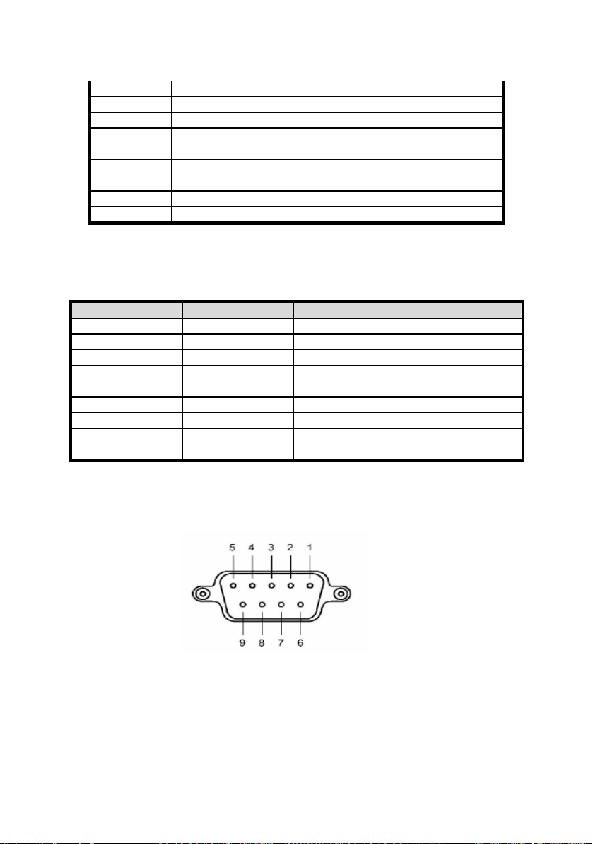
Serial Interface
DB9 Connecter Pin define
RS-232 Interface
Serial Interface Signal

Introduction •5
PIN Function Define
1 DCD
2 TXD
3 RXD
4 ------
5 GND
6 DTR
7 CTS
8 RTS
9 ------
RS-422 Interface
Serial Interface Signal
PIN Function Define
1 RX-
2 RX+
3 TX+
4 TX-
5 GND
6 ------
7 ------
8 ------
9 ------
RS-485 Interface
Serial Interface Signal
PIN Function Define
1 ------
2 ------
3 DATA+
4 DATA-
5 GND
6 ------
6 •Introduction
7 ------
8 ------
9 ------
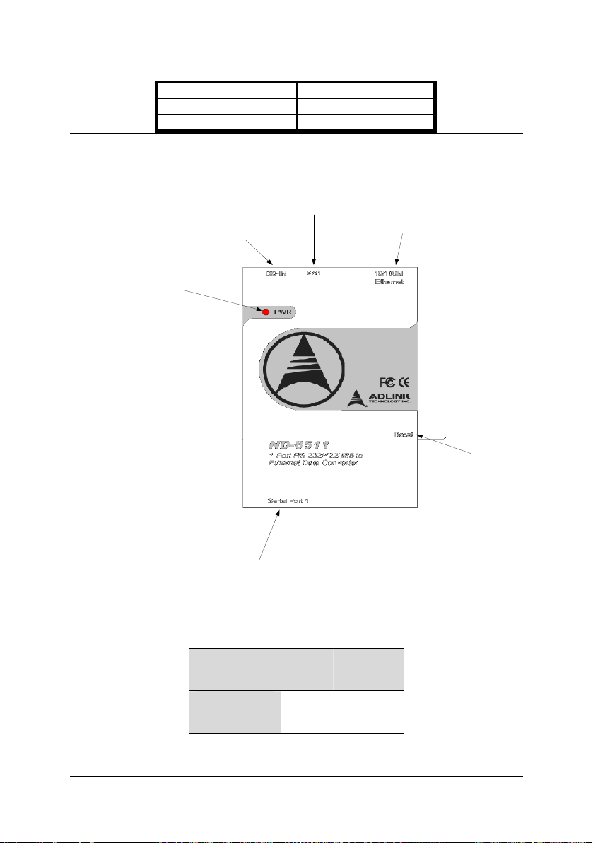
1.5 Form Factor
DC12V~DC24V
Power Input
Reset Push
Button
10/100M
Ethernet RJ45
Connector
RS232/422/485 DB-9
Connector
RS232/422/485
Mode Select DIP
Switch(For ND8511
only)
Power LED
DIP Setting for ND-8511
Interface Bit 1 Bit 2
RS-232 OFF OFF

Introduction •7
RS-485 ON OFF
RS-422 OFF ON

8 •Introduction
1.6 Package Checklist
•One ND-8511 or ND-8511D
•Power Adapter (110V/230V universal)
•NULL MODEM connector
•ADLINK ALL-IN-ONE CD with ND-8511(D) Configuration utility,
COM Port re-director utility and User’s Guide

Installation •9
2
Installation
2.1 Install ND-8511(D) Configuration Utility
2.1.1 Install the Utility
1. Insert ADLINK ALL-IN-ONE CD into your CD-ROM drive.
2. Because the ND-8511(D) configuration utility (Installer) need Microsoft
.NET Framework component for operation, please install the
component first. In the ADLINK ALL-IN-ONE CD, three versions of
Microsoft .NET Framework component are provided “ADLINK ALL-IN-
ONE CD -> NuDAM -> ND-8511 -> Microsoft .NET Framework”.
Please select the correct language version for your system.
3. Go to the “ADLINK ALL-IN-ONE CD -> NuDAM -> ND-8511” directory,
Click the ND-8511(D) configuration utility (Installer.msi) to open the
installation wizard window.
4. Respond to the installation wizard prompts.
2.1.2 Install the Patch
1. After installing the ND-8511(D) configuration utility (Installer), please go
to “ADLINK ALL-IN-ONE CD -> NuDAM -> ND-8511” directory and
click the patch file for the configuration utility (ND-8511.exe).
2. Installation wizard will ask you to set the installation directory of the
patch file, please make sure that the directory must be the same of
10 •Installation
the installation directory of the ND-8511(D) configuration utility
3. Respond to the installation wizard prompts.
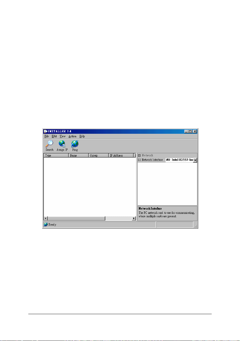
2.1.3 RUN the Installer
1. Click the Start button on the Task Bar and select
“Programs\Installer\Installer” to start the ND-8511(D) configuration
utility. The utility main dialog box displays.
2. To search for devices, click the Search icon or select Search Network
from the Action menu. (The default settings are IP: 192.168.0.1, Net
Mask: 255.255.255.0, Gateway: 192.168.0.254. Users can change
host’s IP to 192.168.0.xxx to be the same Domain as the ND-8511, and
then click the Search icon to find the ND-8511).
2.1.4 Assign IP Address
After find ND-8511 as the description on Section 2.1.3, users can now
change its IP setting, and search for the ND-8511 again. The following
dialog box shows a device found on the network.

Installation •11
If the ND-8511(D) device doesn't show up after searching, then the device
might not have a valid IP address assigned. Please use the Assign IP
Address feature to set a specific IP address on the device. To do this,
please follow the procedures in “Section 2.1.8 Serial Port Login” to assign
the correct IP address.
To change the IP address, first select the device from the list, then click the
Assign IP icon or select Assign IP Address from the Action menu. The
hardware address and IP address are loaded into the Assign IP Address
dialog box.
Enter the new IP Address and click OK. The new IP Address will appear in
the main window.
2.1.5 Test the IP Address
To test the IP Address, select the device from the main window list, then
click the Ping icon, or select Ping from the Action menu. The Ping Device
dialog box shows the IP Address of the selected device. Click the Ping
button and the results will be displayed in the Status window. Use the Clear
Status button to clear the window so you can Ping the device again. Click
the Close button to close the dialog box and return to the main window.

12 •Installation
2.1.6 Opening a Configuration Window
To configure the unit via a Web browser, first click on one of the devices
listed in the window, then click the Web icon. The Web-Manager window
displays in your browser.
To configure the unit via a Telnet session, first click on one of the devices
listed in the window, then click the Telnet icon. The Setup Mode window
displays.
2.1.7 ARP and Telnet
The unit’s IP address must be configured before a network connection is
available. If the unit has no IP address, you can use Address Resolution
Protocol (ARP) method from UNIX and Windows-based systems to assign
a temporary IP address. If you want to initially configure the unit through the
network, follow these steps:
1. On a UNIX or Windows-based host, create an entry in the host's ARP
table using the intended IP address and the hardware address of the
unit, which is found on the product label on the bottom of the unit. arp -s
191.12.3.77 00:20:4a:xx:xx:xx
Note: For the ARP command to work on Windows 95, the ARP table on
the PC must have at least one IP address defined other than its own.
2. If you are using Windows 95, type ARP -A at the DOS command prompt
to verify that there is at least one entry in the ARP table. If the local
machine is the only entry, ping another IP address on your network to
build a new entry in the ARP table; the IP address must be a host other
than the machine on which you are working. Once there is at least one
This manual suits for next models
1
Table of contents
Other ADLINK Technology Media Converter manuals


Popular Media Converter manuals by other brands


BZB Gear
BZB Gear BG-UHD-SCVEA user manual

Keysight
Keysight 11667C Operating and service manual

Klemsan
Klemsan TES-4 user manual

Stahl
Stahl 9721/13-11 Series operating instructions

Omnitron Systems Technology
Omnitron Systems Technology 8249-0 iConverter User instructions

MD-Tech
MD-Tech PHEV User and installation manual


