ADS-tec opc6115 User manual

User Manual
Industrial PCs
OPC6115/6315
Version 2.0

OPC6115/6315 1
© ads-tec GmbH • Heinrich-Hertz-Str. 1 •72622 Nürtingen
Index
1Remarks 3
1.1 Relevant Documentation for this device 3
1.2 Used Symbol Explanation 3
1.3Data, Figures, Modifications 3
1.4 Trademarks 4
1.5 Copyright 4
1.6 Environmental Conditions 5
1.7 Standards 6
1.8 Equipment Versions 6
1.9 Scope of Delivery 7
2Notes on Operation & Safety 8
2.1 Operation Location 8
2.2 Damage Caused By Improper Use 9
2.3 Warranty / Repair 9
2.4 Treatment and Disposal of Lithium Batteries 9
2.5 Notes on Safety 9
3Mounting 10
3.1 Mounting Options 10
3.2 External Device Dimensions OPC6115 11
3.3 External Device Dimensions OPC6315 13
3.4 Mounting procedure 15
4Add-On Card Installation 16
4.1 Pre-installation notes 16
4.2 Notes on configuring the add-on card (PnP) 16
4.3 Installing add-on cards 16
5Commissioning 17
5.1 Available Interfaces 17
5.2 Cable installation 18
5.3 Order of Steps during Commissioning 18
5.4 Check for operational Readiness 18
6Operation 19
6.1 Front Control Keys 19
6.2 Softkeyboard 21
6.3 TouchScreen 22
6.4 Status Indicators 22

OPC6115/6315 2
© ads-tec GmbH • Heinrich-Hertz-Str. 1 • 72622 Nürtingen
7Interfaces 23
7.1 Interface configuration 23
7.2 24V DC Power Supply 23
7.3 115/230V AC Power supply 24
7.4 Speakers 25
7.5 USB-Interface 26
7.6 PS/2 Interface 27
7.7 Network Connection (RJ45) 27
7.8 Serial COM Interface (RS232) 28
7.9 DVI- Interface 29
8Drives 31
9Software-/Driver-Installation 32
9.1 Configuration Center 34
9.1.1 Automatic Brightness Adaption 35
9.1.2 COM Input Configuration 36
9.1.3 Ignition 36
9.1.4 USB-Lock Function 37
9.1.5 On/Off Button Configuration 38
9.1.6 Exemplary RFID Application 39
9.1.7 Softkeyboard 39
9.1.8 Screen Mob 40
9.1.9 Softkeyboard 40
10 Technical Details 41
11 Service & Support 42
11.1 ads-tec Support 42
11.2 Company adress 42

OPC6115/6315 3
© ads-tec GmbH • Heinrich-Hertz-Str. 1 •72622 Nürtingen
1 Remarks
1.1 Relevant Documentation for this device
The following documents are essential for setting up and operating this device:
User Manual (This Documentation):
Contains information for installation, commissioning and operating the device along with technical data
of the device hardware.
Website:
By using the website www.ads-tec.de, you can download drivers, software, user manuals, leaflets and
flyers from the Download section on the website.
Note:
We would recommend you make use of our website contents (www.ads-tec.de) in
order to ensure an optimised data quality and to be quickly and comprehensively
informed of any technical modification.
Service-CD:
Contains Drivers and User Manuals.
1.2 Used Symbol Explanation
Warning:
The "Warning" symbol refers to activities which might cause personal injury
or damage to the hardware or software!
Note:
The "Note" symbol familiarises you with conditions to be observed in order to
ensure flawless operation. Additionally, hints and advice are given for a more
efficient use of the device and for software optimisation.
1.3 Data, Figures, Modifications
All texts, data and figures are non-binding. We reserve the right of modification in accordance with
technological progress. At that point in time when the products leave our premises, they comply with all
currently applicable legal requirements and regulations. The operator/operating company is
independently responsible for compliance with and observance of any subsequently introduced
technical innovations and new legal requirements, as well as for all usual obligations of the
operator/operating company

OPC6115/6315 4
© ads-tec GmbH • Heinrich-Hertz-Str. 1 • 72622 Nürtingen
1.4 Trademarks
It is hereby notified that any software and/or hardware trademarks further to any company brand names
as mentioned in this User’s Guide are all strictly subject to the various trademark, brand name and
patent protection rights.
Windows®, Windows® CE are registered trademarks of Microsoft Corp.
Intel®, Pentium®, Atom™ , Core™2 are registered trademarks of Intel Corp.
IBM®, PS/2® and VGA® are registered trademarks of IBM Corp.
CompactFlash™ and CF™ are registered trademarks of SanDisk Corp.
RITTAL® is a registered trademark of the Rittal Werk Rudolf Loh GmbH & Co. KG.
Any further additional trademarks and/or brand names herein, be they domestic or international, are
hereby duly acknowledged.
1.5 Copyright
This manual, including all contained figures, is protected by copyright law. Any use for third parties non-
compliant with the copyright provisions is prohibited. Any reproduction, translation as well as electronic
and photographic archiving and modification shall only be permitted after explicit written authorisation by
ads-tec GmbH.
Any party in violation of this provision shall be obliged to damage compensation.

OPC6115/6315 5
© ads-tec GmbH • Heinrich-Hertz-Str. 1 •72622 Nürtingen
1.6 Environmental Conditions
The device may be operated under the following conditions. Failure to observe these specifications will
terminate any warranty for this device. Ads-tec cannot be held liable for any damages arising due to
improper use and handling.
Temperature for devices including a fan
in operation 5 … 45°C
for storage -20 … 60°C
Temperature for devices without a fan
in operation 5 … 40°C
for storage -20 … 40°C
Humidity:
In operation 10 … 85% without condensate
For storage 10 … 85% without condensate
Vibration resistance
In operation 1 G, 10 … 500 Hz
(DIN EN 60068-2-6)
Shock resistance
In operation 5 G, with a half-wave of 30 ms duration
(DIN EN 60068-2-27)

OPC6115/6315 6
© ads-tec GmbH • Heinrich-Hertz-Str. 1 • 72622 Nürtingen
1.7 Standards
This device complies with the requirements and protective aims of the following EC regulations:
Standards
This device meets the test requirements for granting the CE sign according to
the European test standards EN 61000-6-4 and EN 61000-6-2
This device complies with the test requirements in accordance with EN 60950
(VDE0805, IEC950) "Safety of Information Technology Equipment"
The device meets the EN 60068-2-6 test requirements (sinus excitation).
This device meets the EN 60068-2-27 test requirements (shock resistance
test)
Note:
A respective conformity declaration for the authority in charge is available at the
manufacturer and may be viewed on request.
All connected components, as well as cable connections must also meet
these requirements for compliance with the EMC legislation. For this reason,
screened bus and LAN cables including screened connectors must be used
and installed according to the instructions in this user manual.
Note:
By using the CE conformity declaration in this document, you can find
detailed information about the standards applicable to this device.
Warning:
This is equipment of class A. This unit might cause radio interferences in
living areas; in this case the operator might be obliged to take suitable
protective measures at the operator’s expense
1.8 Equipment Versions
The system is available in two equipment versions:
Platform including a Flash SSD:
Platform without any rotating mass storage medium (hard disc, etc.) and with an embedded operating
system (Windows CE 6.0 / XP embedded) for stationary use with a standard Ethernet or with radio
networking cards installed on moving commissioning / forklift equipment.
Platform including a hard disc:
Equipped with a hard disc for stationary use, e.g. in the manufacturing department using a standard
operating system.

OPC6115/6315 7
© ads-tec GmbH • Heinrich-Hertz-Str. 1 •72622 Nürtingen
1.9 Scope of Delivery
Please check that all of the following components are contained in the packaging:
1 x device
With 230 V AC devices: Power cable including standard power plug for
non-heated devices
With 24 V DC devices: 3-pin COMBICON plug from Phoenix Contact:
COMBICON MC 2,5/3-STF-5,08 (already plugged in the device socket)
Installation kit for installation
Optional Scope of delivery:
Operating System

OPC6115/6315 8
© ads-tec GmbH • Heinrich-Hertz-Str. 1 • 72622 Nürtingen
2 Notes on Operation & Safety
This device contains electrical voltages and extremely sensitive components. Intervention by the user is
only designated for establishing the required cable connections. The manufacturer or a service partner
authorised by the manufacturer should be consulted if you plan to make further modifications. Before
beginning any works on this device, it must be disconnected from the power supply. Suitable measures
for avoiding any electrostatic discharges towards components must be taken. If the device is opened by
an unauthorised person, hazards for the user might arise and any warranty claim will cease.
General Instructions
All users must read this manual and have access to it at all times
Installation, commissioning and operation may only be carried out by trained
and qualified staff
The security instructions and the manual itself must be observed by all
persons who work with this device
At the location of use, the valid guidelines and regulations for accident
prevention must be observed
The manual contains the most important instructions on how to use this device
in a safe way
Appropriate storage, proper transport, installation and commissioning, as well
as careful operation are prerequisites for ensuring safe and proper operation
of this device
The device can be cleaned by using a soft cloth and a commercially available
glass cleaning agent (e.g. Sidolin) with low alcohol content.
Warning:
Any installation works on the device are only permitted if the power supply is
switched off, and handling the device is safe.
2.1 Operation Location
The control system is designed for use inside a switching cabinet. You must ensure compliance with the
specified environmental conditions. Using the device in non-specified environments, for example on
board ships, or in areas that might contain explosive gases, or in extreme heights is prohibited.
Warning:
For the prevention of water condensate accumulation, the unit should be turned
ON only when it reaches ambient temperature. This particularly applies when the
unit is subject to extreme temperature fluctuations and/or variations.
Avoid overheating during unit operations; the unit must not be exposed to direct
sunlight or any other direct light or heat sources.

OPC6115/6315 9
© ads-tec GmbH • Heinrich-Hertz-Str. 1 •72622 Nürtingen
2.2 Damage Caused By Improper Use
This device must immediately be shut down and protected from any accidental commissioning if the
operating system shows any obvious damage caused by, for example, improper operating or storage
conditions, or by improper use or handling.
2.3 Warranty / Repair
During the warranty period, any repair must only be carried out by the manufacturer or by a person
authorised by the manufacturer.
2.4 Treatment and Disposal of Lithium Batteries
This device contains a lithium battery for supplying the system clock with power as long as the supply
voltage is not connected. The battery has a life cycle of 3 - 5 years depending on which load is applied.
Note:
The more the battery is exposed to higher temperatures, the faster it ages.
Warning:
There is an acute risk of explosion should the wrong type of battery be used.
Warning:
Do not put lithium batteries into a fire, do not solder on the cell body, do not
recharge them, open them, short-circuit them, do not reverse their polarity or heat
them up over 100°C; dispose of them properly and protect lithium batteries from
direct sun light, humidity and condensation.
Lithium batteries may only be replaced by the same type, or by a type recommended by the
manufacturer.
The lithium battery must be disposed of according to the local legislation at the end of its life cycle.
2.5 Notes on Safety
Warning:
Installation works at the device are only permitted if the device is disconnected
from the power supply and protected from accidental switch-on.
Note:
Always adhere to the safety measures applicable when handling components at
risk of being destructed by electrostatic discharges..
(DIN EN 61340-5-1 / DIN EN 61340-5-2)

OPC6115/6315 10
© ads-tec GmbH • Heinrich-Hertz-Str. 1 • 72622 Nürtingen
3 Mounting
3.1 Mounting Options
This device is intended for integration into switch panels or switching cabinets. In order to allow for a
safe installation and operation (connector access), these switch panels or control desks must be
accessible from the back. The device can be integrated into switching cabinets with a wall thickness of
2..6 mm. We recommend a minimum of 3 mm for correct installation with an IP65 front protection class.
Warning:
To avoid overheating in operation: The device must not be exposed to direct
radiation by sunlight or any other light or heat source.
If the device is integrated in a panel, casing or similar enclosures, you must ensure
that no heat accumulation builds up. The maximum permissible environmental
temperature must never be exceeded.
Devices including a data drive must only perpendicularly be integrated. Any
deviation must be agreed with ads-tec.
The IP65 protection class is only achieved after correct installation.
If the device is delivered with a CD/DVD-ROM drive, sufficient space (approx.
130mm) must be provided on the left-hand side if viewing the drive from the front,
in order to allow proper opening of the drive.
Note:
When selecting the enclosure for integration, the power dissipation total of
the system including that of all integrated PCBs must be taken into account.
The enclosure must be calculated in such a way that the maximum
environmental temperature is not exceeded in any case.

OPC6115/6315 11
© ads-tec GmbH • Heinrich-Hertz-Str. 1 •72622 Nürtingen
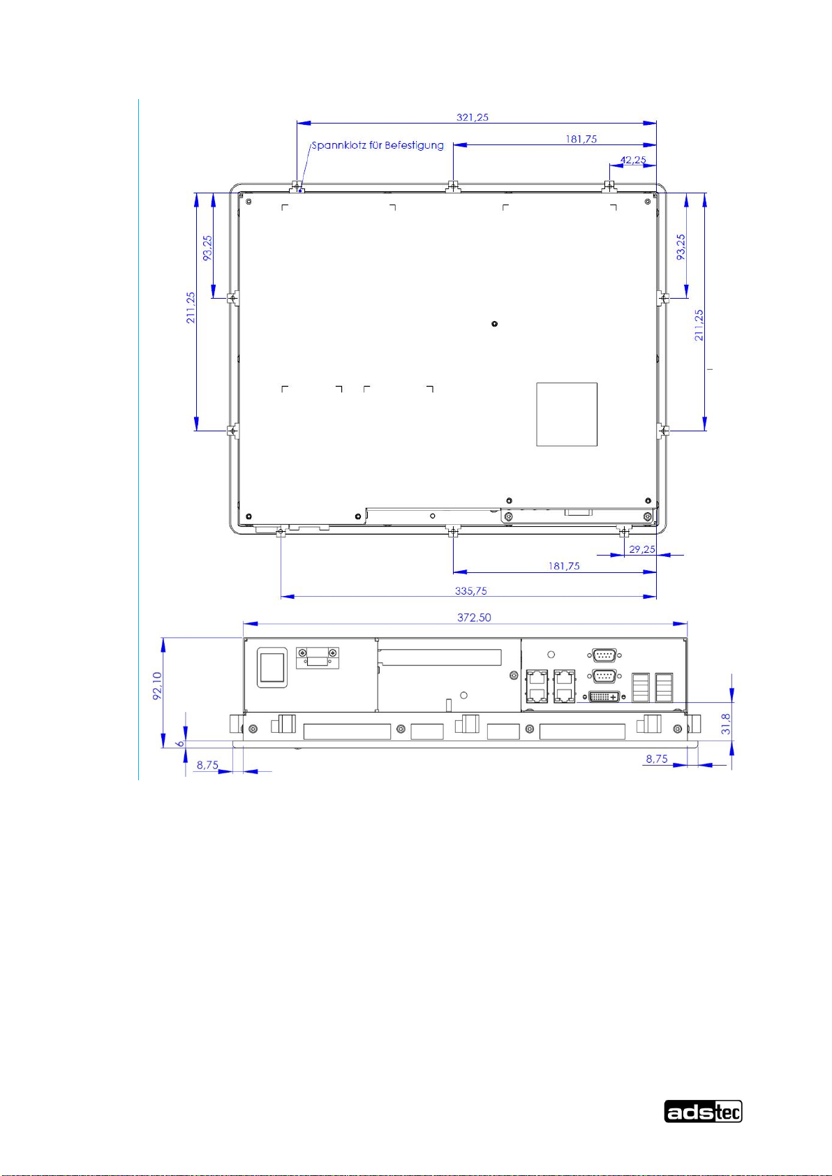
3.2 External Device Dimensions OPC6115
OPC6115/6315 12
© ads-tec GmbH • Heinrich-Hertz-Str. 1 • 72622 Nürtingen
Abb.
1
:
OPC6115/6315 13
© ads-tec GmbH • Heinrich-Hertz-Str. 1 •72622 Nürtingen
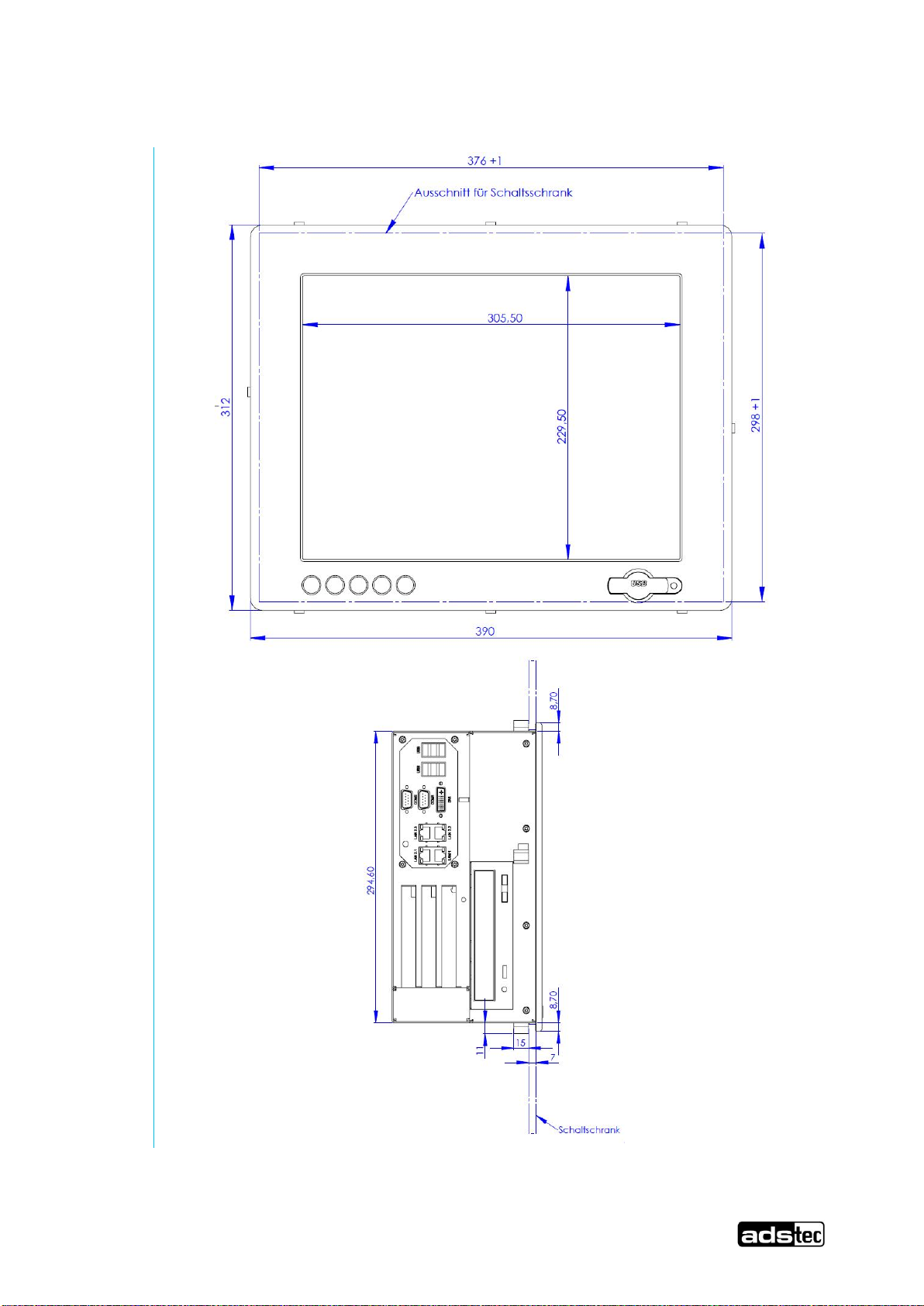
3.3 External Device Dimensions OPC6315

OPC6115/6315 14
© ads-tec GmbH • Heinrich-Hertz-Str. 1 • 72622 Nürtingen
Abb.
2
:

OPC6115/6315 15
© ads-tec GmbH • Heinrich-Hertz-Str. 1 •72622 Nürtingen
3.4 Mounting procedure
Use the drilling template to drill holes according the mounting illustration in the control panel with the
specified threading. Insert the upper screws half way into the control panel and hang the device on the
mounting links. Tighten the screws and insert the rest of the screws.
Warning:
The device must be switched off before connecting or disconnecting any cables in
order to prevent damage to the electronics!
The device may only be switched on after acclimatising to the ambient temperature
in order to avoid condensate accumulation. Make sure to meet the permissible
voltage requirements for this device.
After switching off and before switching on you must wait for at least 5 seconds.
Note:
The device is connected to the power supply using a lead out terminal with a
screw connection. A ground connection does not have to be made, because
the grounding conductor of the device plug or supply connection serves this
purpose. If additional grounding conductors are attached to a grounding
screw, a wire diameter of at least 2.5 mm² is specified.

OPC6115/6315 16
© ads-tec GmbH • Heinrich-Hertz-Str. 1 • 72622 Nürtingen
4 Add-On Card Installation
4.1 Pre-installation notes
The user can install CompactFlash or PCI add-on cards such as Interbus cards in the device. The card
slot is accessed by taking off the back cover. The crosshead screws on the back of the control system
should be removed for this purpose.
Achtung:
The components in the device are highly sensitive products, which can be
destroyed or impaired by improper handling. The same applies to the PC add-on
cards to be installed. Therefore the appropriate measures have to be implemented
in all cases to avoid electrostatic shock to the components upon contact.
4.2 Notes on configuring the add-on card (PnP)
The Ethernet and IDE controllers on the adsX board are connected via an internal PCI bus. Therefore
the addresses and IRQs are automatically assigned by the BIOS. The following should be considered
when installing or reconfiguring ISA cards:
•Install and switch on device without ISA cards and then note down the assigned IRQs and addresses.
•Install additional ISA cards in such a way that the IRQs assigned to PCI controllers are not used again.
•Reserve IRQs for ISA cards in the BIOS.
4.3 Installing add-on cards
• •Switch off the device and all units connected to the PC and disconnect them from the power supply.
•Unscrew the cover screws using a matching screwdriver and carefully remove the cover.
Warning:
The cover may be connected to mechanical parts in the device by a grounding
wire! Do not remove the cover with force...
•Reduce electrostatic charge by implementing the appropriate measures (see above), remove the add-
on card from the packaging, place it in the slot and bolt it to the card mount.
•Each ISA card should be fastened in the matching slot with a clamp to prevent the card from falling out.
•Reconnect the grounding conductor if it has been removed and replace the cover while paying
attention to the side clips as the case may be.
•Tighten all of the screws on the cover again.

OPC6115/6315 17
© ads-tec GmbH • Heinrich-Hertz-Str. 1 •72622 Nürtingen
5 Commissioning
The power supply connection and interfaces of this device are installed underneath a protective cover.
This cover has to be removed in order to connect the power supply lead and the interface cables.
All supply leads and all required data leads have to be connected before commissioning. All supply
leads and all required data leads have to be connected before commissioning.
Warning:
The device must be switched off before connecting or disconnecting any cables in
order to prevent damage to the electronics!
The device may only be switched on after acclimatising to the ambient temperature
in order to avoid condensate accumulation. Make sure to meet the permissible
voltage requirements for this device.
After switching off and before switching on you must wait for at least 5 seconds.
Note:
The screen of a data cable must always be connected with the connector housing
(EMC).
Under the embedded operating system, interfaces must explicitly be enabled
and required drivers must be installed in order to be able to use them.
5.1 Available Interfaces
Abb.
3
:
Note:
If the case is connected with earth potential at the provided PE contact (e.g. by
connecting the PE contact with the device plug), the electrical insulation is no
longer given. This also applies if the device is installed by using a metal retainer
clip.
If you want to have the device electrically insulated from the power supply,
you have to use a method of installation that ensures appropriate insulation.
Pos:18 /Datentechnik/Inbetriebnahme/Reihenfolgeder Inbetriebnahme/Reihenfolgeder Inbetriebnahmefür VMT 60xx-Serie @ 1\mod_1222073159179_6.doc@ 4100 @

OPC6115/6315 18
© ads-tec GmbH • Heinrich-Hertz-Str. 1 • 72622 Nürtingen
5.2 Cable installation
The interfaces as well as power supply plugs for the device are accommodated in the device service
slot.
5.3 Order of Steps during Commissioning
•With 24V DC devices: Connect the power supply cable with the terminals by using cable end sleeves
•Connect cable for serial / parallel data transmission and fasten the screws between the connector plug
and socket
•Plug in all other required cables and protect from accidental disconnection
Pos:19 /Datentechnik/Inbetriebnahme/Betriebsbereitschaftprüfen/Betriebsbereitschaftprüfen für OPC/CPC/PLC/OTC/ITC/VMT-Serie(+Monitore)/ IPC 5100/5500/2400/1100@ 0\mod_1158905578361_6.doc@ 381 @
5.4 Check for operational Readiness
Check the device for any hidden damage potentially caused by improper transport, operating or storage
conditions or by improper use or handling (e.g. smoke development from the device, etc.). If any
damage is detected, the device must be put out of service immediately and protected from accidental
switch-on.

OPC6115/6315 19
© ads-tec GmbH • Heinrich-Hertz-Str. 1 •72622 Nürtingen
6 Operation
6.1 Front Control Keys
Abb.
4
:
Depending on the device equipment version, an operating system (Windows CE.net,
Windows XP embedded or Windows XP Prof.) and a soft keyboard are already installed ex
factory. The keys on the front panel are occupied with the following functions by a specific
driver in the soft keyboard:
Level 1:
Activate and deactivate the soft keyboard for letter/character input
using the touch screen.
Level 2:
Decrease display brightness
Level 1:
Change task (Alt+ESC) in Windows.
Level 2:
Increase display brightness.
Level 1:
Not connected
Level 2:
The volume can be decreased with devices equipped with an
audio output.
Level 1:
Right mouse-key function.
Level 2:
The volume can be increased with devices equipped with an audio
output.
Shift key (SHIFT) for activating the second keyboard level. This
key must be pressed simultaneously with the desired function key
Note:
If the software keyboard is not installed, only the functions for display settings
and volume control are active. The controller display will not be output on the
display, in this case.
The key functions can be modified in accordance with customer specific
requirements. Above described functions are pre-set ex works.
This manual suits for next models
1
Table of contents
Other ADS-tec Industrial PC manuals


