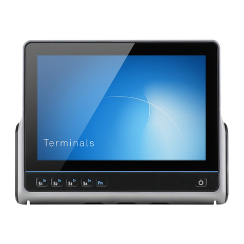
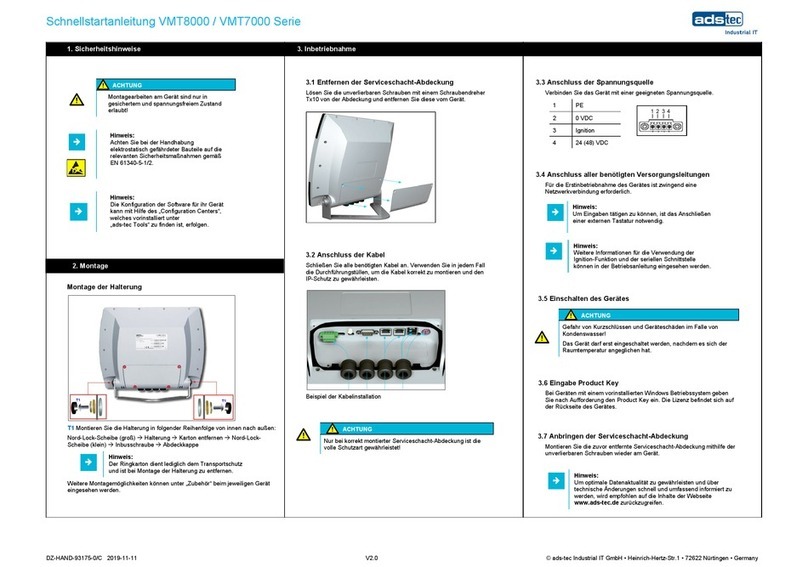
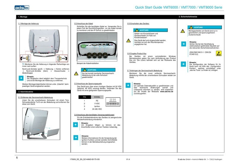
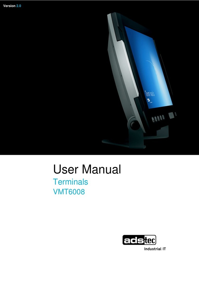
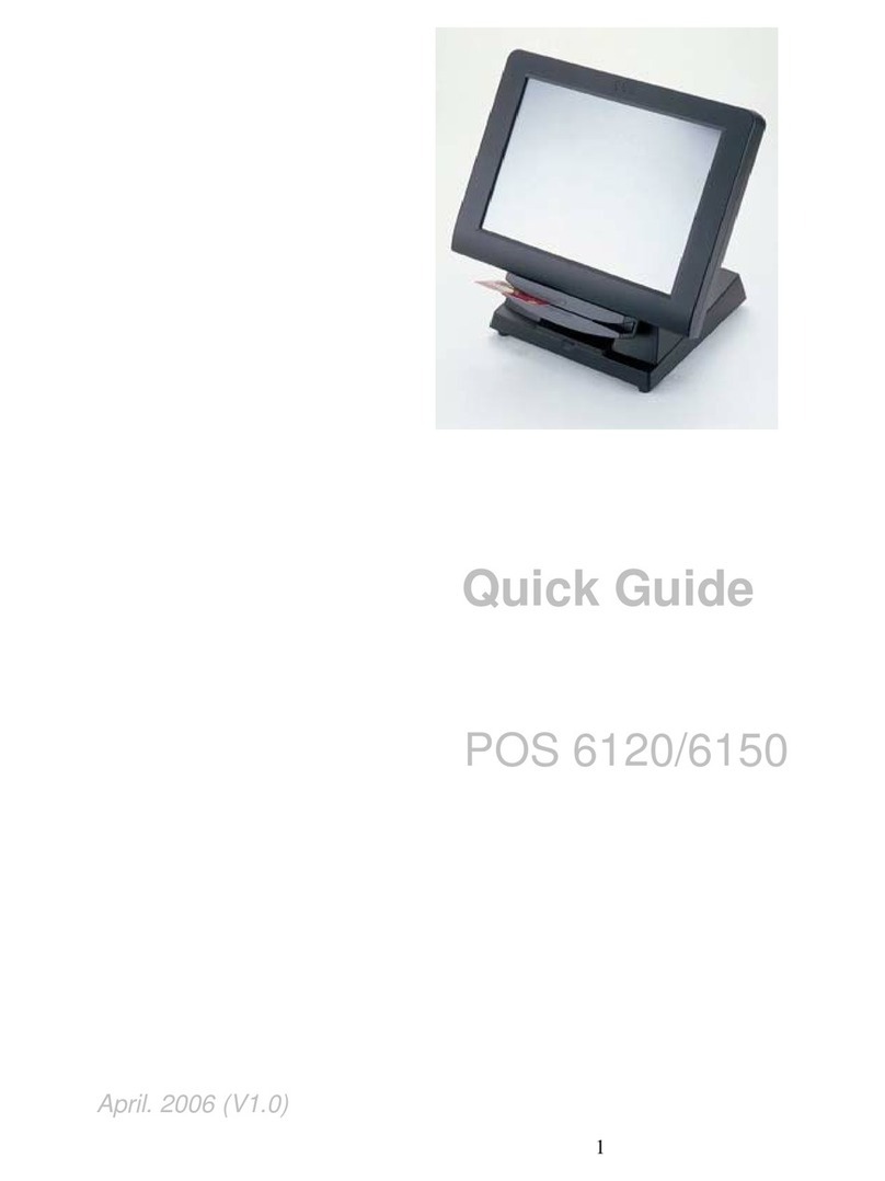
ADS-tec VMT6008 User manual

User Manual
Terminals
VMT6008
Version 1.3

Terminals VMT6008
2 © ads-tec GmbH • Raiffeisenstr.14 • 70771 Leinfelden-Echterdingen
Product Portfolio
Copyright
©ads-tec GmbH
Raiffeisenstr.14
D-70771 Leinfelden-Echterdingen
Germany

T
erminals VMT6008
© ads-tec GmbH • Raiffeisenstr.14 • 70771 Leinfelden-Echterdingen 3
INDEX
ABOUT US.......................................................................................................................................... 5
1REMARKS ................................................................................................................................. 6
1.1 RELEVANT DOCUMENTATION FOR THE DEVICE ....................................................................................6
1.2 EXPLANATION OF USED SYMBOLS ....................................................................................................6
1.3 DATA,FIGURES AND MODIFICATION ................................................................................................6
1.4 TRADE MARKS ...........................................................................................................................7
1.5 COPYRIGHTS.............................................................................................................................7
1.6 ENVIRONMENTAL CONDITIONS .......................................................................................................7
1.7 STANDARDS..............................................................................................................................8
1.8 EQUIPMENT VERSION ..................................................................................................................8
1.9 SCOPE OF DELIVERY....................................................................................................................9
2OPERATING INSTRUCTIONS ....................................................................................................... 10
2.1 OPERATING LOCATION............................................................................................................... 10
2.2 DAMAGE DUE TO IMPROPER USE ...................................................................................................10
2.3 WARRANTY /REPAIR.................................................................................................................11
2.4 TREATMENT AND DISPOSAL OF LITHIUM BATTERIES ...........................................................................11
2.5 NOTES ON SAFETY ....................................................................................................................11
2.6 EXTERNAL DEVICE DIMENSIONS.................................................................................................... 12
3COMMISSIONING..................................................................................................................... 13
3.1 AVAILABLE INTERFACES..............................................................................................................13
3.2 ORDER OF STEPS DURING COMMISSIONING .....................................................................................14
3.3 CHECK FOR OPERATIONAL READINESS ............................................................................................ 15
4OPERATION ............................................................................................................................ 16
4.1 FRONT CONTROL KEYS ...............................................................................................................16
4.2 SOFT KEYBOARD ......................................................................................................................18
4.3 TOUCH SCREEN........................................................................................................................19
4.4 STATUS INDICATORS ................................................................................................................. 20
5INTERFACES............................................................................................................................ 21
5.1 INTERFACE SETUP.....................................................................................................................21
5.2 24 VDC POWER SUPPLY............................................................................................................21
5.3 AUTOSTART FUNCTION (S1) ....................................................................................................... 23
5.4 SPEAKERS ..............................................................................................................................24
5.5 USB CONNECTIONS .................................................................................................................. 25
5.6 PS/2 CONNECTOR .................................................................................................................... 25
5.7 NETWORK CONNECTION (RJ45) ..................................................................................................26
5.8 OPTIONAL RADIO NETWORK CARD.................................................................................................27
5.9 SERIAL COM INTERFACE (RS232) ...............................................................................................28
6DRIVES.................................................................................................................................. 29
6.1 HARD DRIVE /FLASH SSD.......................................................................................................... 29
6.2 EXTERNAL DRIVES .................................................................................................................... 29
7SOFTWARE &DRIVER INSTALLATION........................................................................................... 30

Terminals VMT6008
4 © ads-tec GmbH • Raiffeisenstr.14 • 70771 Leinfelden-Echterdingen
7.1 INSTALLING THE OPERATING SYSTEM ............................................................................................ 30
7.2 TOUCH SCREEN DRIVER INSTALLATION .......................................................................................... 31
7.3 CONFIGURATION CENTER........................................................................................................... 32
7.4 AUTOMATIC BRIGHTNESS ADAPTATION .......................................................................................... 33
7.5 IGNITION............................................................................................................................... 34
7.6 USB LOCK FUNCTION ............................................................................................................... 35
7.7 ON /OFF PUSHBUTTON CONFIGURATION ...................................................................................... 36
7.8 SOFT KEYBOARD ...................................................................................................................... 37
7.9 SCREEN MOB.......................................................................................................................... 37
7.10 SOFT KEYBOARD ...................................................................................................................... 38
8TECHNICAL DETAILS................................................................................................................. 39
8.1 DISPLAY DATA ........................................................................................................................ 39
8.2 COMPUTER DATA ..................................................................................................................... 39
8.3 GENERAL DATA........................................................................................................................ 39
9SERVICE AND SUPPORT............................................................................................................. 40
9.1 ADS-TEC SUPPORT.................................................................................................................... 40
9.2 COMPANY ADDRESS .................................................................................................................. 40
10 COMPONENT REPLACEMENT ....................................................................................................... 41
10.1 OPENING THE SERVICE SLOT ....................................................................................................... 41
10.2 1. REPLACING THE LITHIUM BATTERY ............................................................................................ 43
10.3 2. REPLACING THE FLASH MODULES .............................................................................................. 44
11 DECLARATION OF CE CONFORMITY ............................................................................................. 46

T
erminals VMT6008
© ads-tec GmbH • Raiffeisenstr.14 • 70771 Leinfelden-
E
Pos:1/Datentechni k/AllgemeineHinweise/Wir über uns/Wir überuns@ 2\ mod_1254923190378_6.doc @ 6522@
A
BOUT U
S
ads-tec GmbH
Raiffeisenstr. 14
D-70771 Leinfelden
-
Phone: +49 711 45
8
Fax: +49 711 458
9
www.ads-tec.com
A
s a supplier of h
i
operatin
g
g
roups o
f
up to date and del
system technology.
ads-tec puts entir
e
commissioning - an
d
technology.
The Data Technolo
g
wide ran
g
e of indus
t
ads-tec has special
develops software t
o
Pos: 2 /D aten tec hni k/Al lg emei ne H inw eis e/R ele vante Do kum enta tio nen zum Ger ät/R el evant e D oku ment ati one n f ür O PC / C PC / OT C / VMT /STC @ 2\mod_1268662117522_6.doc@ 7352 @
Echterdingen
S
-
Echterdingen
8
94-0
9
4-990
ig
h tech equipment, ads-tec supports lar
g
e e
n
f
companies with state-of-the-art technolo
g
y, kn
ivery of comprehensive services in the area of
e
solutions for automation into practice - fro
m
d
has particularly specialised in manipulation an
d
g
y division develops and manufactures PC base
d
t
rial PCs, thin clients and embedded systems ava
ised in the adaptation and optimisation of op
o
ols to complement the offered hardware platfor
m
5
n
terprises and
g
lobally
ow how that is always
automation, data and
m
the plannin
g
to the
d
material manipulation
d
solutions and holds a
ilable.
erational systems and
m
s.

Terminals VMT6008
6 © ads-tec GmbH • Raiffeisenstr.14 • 70771 Leinfelden-Echterdingen
1REMARKS
1.1 RELEVANT DOCUMENTATION FOR THE DEVICE
The following documents are essential for setting up and operating this device:
USER MANUAL (THIS DOCUMENTATION):
Contains information for installation, commissioning and operating the device along with
technical data of the device hardware.
WEBSITE
By using the website www.ads-tec.de, you can download drivers, software, user manuals,
leaflets and flyers from the Download section on the website.
Note:
We would recommend you make use of our website contents (www.ads-tec.de) in order
to ensure an optimised data quality and to be quickly and comprehensively informed of
any technical modification.
SERVICE CD:
Contains drivers and user manuals.
Note:
The service CD menu automatically starts if the autostart option for removable media is
activated.
The service CD was created by using Adobe Flash. The service CD menu is even available
if the Flash Player is not installed.
Pos: 3 /D atent echni k/All gemei ne Hin weise/ Erläu terung z u den ver wendet en Sym bole n/Erläu terung z u den ver wendet en Sym bole n @ 0\mod_1158752779484_6.doc@ 141@
1.2 EXPLANATION OF USED SYMBOLS
Warning:
The "Warning" symbol refers to activities which could cause personal injury or damage to
the hardware and software!
Note:
The "Note" symbol describes conditions which unconditionally have to be observed in
order to ensure trouble-free operation. Additionally, hints and advice for the efficient use
of this device and for software optimisation are given using this symbol.
Pos: 4 /D aten tec hni k/Al lg emei ne H inw eis e/D aten, Ab bil dung en, Än der ung en/Dat e n,Ab bild ung en, Än der unge n @ 1\m od_ 123 5480 498 775 _6.d oc @ 5162 @
1.3 DATA,FIGURES AND MODIFICATION
All texts, data and figures are non-binding. All these materials are subject to modification
due to technological advances. Our products comply with all provisions and requirements
of the legislation at the point in time when the products leave our company premises. The
operator/operating company bears sole responsibility for the compliance with any
consecutive new technological development or adherence to any consecutive new
legislatory provision, as well as for the observance of their obligation as the
operator/operating company.
Pos:5/Datentechni k/Allgemei neHinweise/Warenzeichen/Warenzeichen @ 2\mod_1263298182965_6.doc @ 6972@

T
erminals VMT6008
© ads-tec GmbH • Raiffeisenstr.14 • 70771 Leinfelden-Echterdingen 7
1.4 TRADE MARKS
We would like to emphasise that all names of hardware and software products used in this
documentation, as well as all brand names of corresponding companies are subject to the
general copyrights of the intellectual property in terms of trademarks, brand names and
patents.
Windows®, Windows®CE are registered trademarks of Microsoft Corp.
Intel®, Pentium®, Atom™, Core™2, are registered trademarks of Intel Corp.
IBM®, PS/2®and VGA®are registered trademarks of IBM Corp.
CompactFlash®is a registered trademark of the Compact Flash Association.
RITTAL®is a registered trademark of Rittal Werk Rudolf Loh GmbH & Co. KG.
Any other national and international trademarks and product names shall hereby also be
recognised.
Pos:6/Datentechni k/AllgemeineHinweise/Urheberrecht/Urheberrecht @ 0\mod_1158756954232_6.doc@ 153 @
1.5 COPYRIGHTS
This manual including all contained figures is protected by copyright law. Any use of this
manual by a third party in non-compliance with the international copyright law shall hereby
be prohibited. Any reproduction, translation and electronic or photographic archiving or
modification requires previous written agreement by ads-tec GmbH.
In the event of non-compliance, you shall be obliged to compensate for damages.
Pos:7/Datentechni k/Allgemeine Hinweise/Umweltbedingungen/UmweltbedinungenfürVMT60xx-Serie@ 2\mod_1263307758056_6.doc@ 6981 @
1.6 ENVIRONMENTAL CONDITIONS
The device may be operated under the following conditions. Failure to observe these
specifications will terminate any warranty for this device. Ads-tec cannot be held liable for
any damages arising due to improper use and handling.
•Temperature for devices without a heater
In operation -20 ... 55°C
For storage -30 ... 60°C
•Temperature for devices including a heater
In operation -30 ... 55°C
For storage -30 ... 60°C
•Humidity:
In operation 10 … 85% without condensate
For storage 10 … 85% without condensate
•Vibration resistance
Standard EN 60068-2-6 / 1 G, 10 … 150 Hz
Additionally applies MIL-STD 810F (01.2000), annex C. figure 514.5C
(US highway truck transportation)
•Shock resistance
Standard EN 60068-2-27 / 5 G, with a half-wave of 11 ms duration
Pos:8/Datentechni k/Allgemei neHinweise/N ormen/N ormen f ürVMT-Serie@ 2\mod_1263309234182_6.doc @ 6984@

Terminals VMT6008
8 © ads-tec GmbH • Raiffeisenstr.14 • 70771 Leinfelden-Echterdingen
1.7 STANDARDS
This device complies with the requirements and protective aims of the following EC
regulations:
•This device meets the test requirements for granting the CE sign according to the
European test standards EN 61000-6-4 and EN 61000-6-2.
•This device complies with the test requirements in accordance with DIN EN 60950
(VDE0805, IEC950) "Safety of Information Technology Equipment"
•The device meets the DIN EN 60068-2-6 test requirements (sinus excitation).
•The device meets the DIN EN 60068-2-27 test requirements (shock resistance
test).
Note:
All connected components, as well as cable connections must also meet these
requirements for compliance with the EMC legislation. For this reason, screened bus and
LAN cables including screened connectors must be used and installed according to the
instructions in this user manual.
Note:
By using the CE conformity declaration in this document, you can find detailed
information about the standards applicable to this device.
Warning:
This is equipment of class A. This unit might cause radio interferences in living areas; in
this case the operator might be obliged to take suitable protective measures at the
operators’ expense."
Pos: 9 /D atent echni k/All gemei ne Hin weise/ Auss tattung svar iant en/Aus stat tungs varia nten für VM T60 08 @ 2\mo d_127 2445 94224 8_6.d oc @ 7711 @
1.8 EQUIPMENT VERSION
The system is available in the following equipment version:
Platform including a Flash SSD:
Platform without any rotating mass storage medium (hard disc, etc.) and with an
embedded operating system (Windows CE 6.0 / XP embedded) for stationary use with a
standard Ethernet or with radio networking cards installed on moving commissioning /
forklift equipment.
Pos:10/Datentechni k/AllgemeineHinweise/Lieferumfang/Lieferumfang fürVMT 60xx-Serie @ 2\mod_1263299644184_6.doc @ 6976 @

T
erminals VMT6008
© ads-tec GmbH • Raiffeisenstr.14 • 70771 Leinfelden-Echterdingen 9
1.9 SCOPE OF DELIVERY
Please check that all of the following components are contained in the packaging:
•1 x device
•4-pin lead-through connector from Phoenix Contact, COMBICON MC
1.5/4-STF3.81
•Service CD
•Protective covers
Optional delivery scope
•Operating system
•Installation kit
Pos: 11 /D atent ech nik/Bet riebs hin weise/ Betri ebsort /Betr iebs ort für VM T-Ser ie @ 2\m od_12 6884 13529 05_6. doc @ 748 6 @

Terminals VMT6008
10 © ads-tec GmbH • Raiffeisenstr.14 • 70771 Leinfelden-Echterdingen
2OPERATING INSTRUCTIONS
This device contains electrical voltages and extremely sensitive components. The
manufacturer, or a service partner authorised by the manufacturer, should be consulted if
you plan to make any modifications. For this type of work, the device must be switched off
at the mains and the power lead must be disconnected. Suitable measures for avoiding
electrostatic discharge towards parts of the components when touching the equipment
must be taken. If the device is opened by an unauthorised person, hazards for the user
might arise and any warranty claim will cease.
General instructions:
•All users must read this manual and have access to it at all times.
•Installation, commissioning and operation may only be carried out by trained and
qualified staff.
•The security instructions and the manual itself must be observed by all persons
who work with this device.
•At the location of use the valid guidelines and regulations for accident prevention
must be observed.
•The manual contains the most important instructions on how to use this device in
a safe way.
•Appropriate storage, proper transport, installation and commissioning, as well as
careful operation are prerequisites for ensuring safe and proper operation of the
device.
•The device can be cleaned by using a soft cloth and a commercially available glass
cleaning agent (e.g. "Sidolin") with low alcohol content.
Warning:
Any leads (e.g. power leads, interface cables) may only be connected if the device is
switched off in order to avoid damaging the device.
2.1 OPERATING LOCATION
The VMT control system is designed for use on support arm systems or on moving
transport equipment (like commissioning trolleys, forklifts or similar). You must take care
that the environmental conditions specified in the technical data specification are met.
Using the device in non-specified environments, for example, on board ships, or in areas
that might contain explosive gases or in extreme heights is prohibited.
Warning:
The device may only be switched on after acclimatising to the ambient temperature in
order to avoid condensate accumulation. The same applies if the device has previously
been exposed to extreme temperature variations.
To avoid overheating in operation: The device must not be exposed to direct radiation by
sunlight or any other light or heat source.
2.2 DAMAGE DUE TO IMPROPER USE
If the control system shows any obvious damage, e.g. caused by improper operating or
storage conditions or by improper use or handling, you must immediately put the device
out of operation and protect it from being accidentally switched on.
Pos: 13 /D atent ech nik/Bet riebs hin weise/ Gewä hrleis tung / R epara tur/G ewähr leist ung / Repar atur @ 0\ mod_11 5882 80544 27_6. doc @ 223 @

T
erminals VMT6008
© ads-tec GmbH • Raiffeisenstr.14 • 70771 Leinfelden-Echterdingen 11
2.3 WARRANTY /REPAIR
During the warranty period, any repair must be carried out by the manufacturer or by
persons duly authorised by the manufacturer only.
Pos: 14 /D atent ech nik/Bet riebs hin weise/ Behan dlung un d Ents orgung v on Lithi um-B atteri en/Be handl ung un d Ents orgung vo n Lithiu m-Batterien@ 1\mod_1247056308470_6.doc @ 5922@
2.4 TREATMENT AND DISPOSAL OF LITHIUM BATTERIES
This device contains a lithium battery for supplying the system clock with power as long as
the supply voltage is not connected. The battery has a life cycle of 3 - 5 years depending
on which load is applied.
Note:
The more the battery is exposed to higher temperatures, the faster it ages.
Warning:
There is an acute risk of explosion should the wrong type of battery be used.
Warning:
Do not put lithium batteries into a fire, do not solder on the cell body, do not recharge
them, open them, short-circuit them, do not reverse their polarity or heat them up over
100°C; dispose of them properly and protect lithium batteries from direct sun light,
humidity and condensation.
Lithium batteries may only be replaced by the same type, or by a type recommended by
the manufacturer.
The lithium battery must be disposed of according to the local legislation at the end of its
life cycle.
Pos:15/Datentechni k/Betriebshinweise/Sicherheits hinweise/Sicherheitshinweis e @ 0\mod_1162458821197_6.doc@ 1558@
2.5 NOTES ON SAFETY
Warning:
Installation works at the device are only permitted if the device is disconnected from the
power supply and protected from accidental switch-on.
Note:
Always adhere to the safety measures applicable when handling components at risk of
being destructed by electrostatic discharges.
(EN 61340-5-1 / EN 61340-5-2)
Pos:16/Datentechni k/Montage/Montageskizzen/Außenabmessungendes Geräts/Montageskizze / Außenabmessungen fürVMT 6008@ 2\mod_1260947908815_6.doc @ 6926@

Terminals VMT6008
12 © ads-tec GmbH • Raiffeisenstr.14 • 70771 Leinfelden-Echterdingen
2.6 EXTERNAL DEVICE DIMENSIONS
Pos:17/Datentechni k/Inbetriebnahme/Systemmer kmale/Inbetriebnahme für VMT6008@ 2\mod_1268057894969_6.doc@ 7292 @

T
erminals VMT6008
© ads-tec GmbH • Raiffeisenstr.14 • 70771 Leinfelden-Echterdingen 13
3COMMISSIONING
The power supply connection and interfaces of this device are installed underneath a
protective cover. This cover has to be removed in order to connect the power supply lead
and the interface cables.
All supply leads and all required data leads have to be connected before commissioning.
Warning:
The device must be switched off before connecting or disconnecting any cables in order
to prevent damage to the electronics!
The device may only be switched on after acclimatising to the ambient temperature in
order to avoid condensate accumulation. Make sure to meet the permissible voltage
requirements for this device.
After switching off and before switching on you must wait for at least 5 seconds.
Note:
The screen of a data cable must always be connected with the connector housing (EMC).
Under the embedded operating system, interfaces must explicitly be enabled and required
drivers must be installed in order to be able to use them.
3.1 AVAILABLE INTERFACES
Note:
If the case is connected with earth potential at the provided PE contact (e.g. by
connecting the PE contact with the device plug), the electrical insulation is no longer
given. This also applies if the device is installed by using a metal retainer clip.
If you want to have the device electrically insulated from the power supply, you have to
use a method of installation that ensures appropriate insulation.
Pos:18/Datentechni k/Inbetriebnahme/Reihenfolge der Inbetriebnahme/Reihenfolge der InbetriebnahmefürVMT 60xx-Serie@1\ mod_1222073159179_6.doc @ 4100@

Terminals VMT6008
14 © ads-tec GmbH • Raiffeisenstr.14 • 70771 Leinfelden-Echterdingen
3.2 ORDER OF STEPS DURING COMMISSIONING
REMOVING THE LID FROM THE SERVICE SLOT
Loosen the undetachable screws on the service slot cover by using a Torx Tx10 wrench
and subsequently remove the service slot cover from the device.
CONNECTING THE CABLES
Please connect all required cables. Use grommets in this case, in order to install the cables
correctly and to avoid any potential damage to the cables.
Note:
A cable installation kit, which includes grommets for several cable diameters, is available
as an option.

T
erminals VMT6008
© ads-tec GmbH • Raiffeisenstr.14 • 70771 Leinfelden-Echterdingen 15
Warning:
The indicated protection class is only fully guaranteed if the case cover is correctly
installed!
Pos: 19 /D atent echni k/Inbet rieb nahme/ Betr iebsber eitsc haft pr üfen/ Betrieb sberei tsch aft prüf en für OPC/ CPC/ PLC/OT C/ITC /VMT- Serie( +Monit ore) /IPC 5100/5500/2400/1100@ 0\mod_1158905578361_6.doc@ 381 @
3.3 CHECK FOR OPERATIONAL READINESS
Check the device for any hidden damage potentially caused by improper transport,
operating or storage conditions or by improper use or handling (e.g. smoke development
from the device, etc.). If any damage is detected, the device must be put out of service
immediately and protected from accidental switch-on.
Pos: 20 /D atent ech nik/Be dienu ng/Fr ontsei tig eT asten /Fro ntseiti ge Bedi enta sten für VMT 6 0xx-Ser ie @ 2\m od_12 7244 52018 29_6. doc @ 7703@

Terminals VMT6008
16 © ads-tec GmbH • Raiffeisenstr.14 • 70771 Leinfelden-Echterdingen
4OPERATION
4.1 FRONT CONTROL KEYS
VERSION 1(REVISION UNTIL Q1/2010)
ON / OFF pushbutton of the device (ATX functionality)
The operating system is shut down, but the device is not disconnected
from the input voltage.
Depending on the actual equipment version, each device is equipped with an operating
system (Windows CE 6.0, Windows XP embedded or Windows XP Professional) ex works,
and a soft keyboard is installed. The keys on the front panel are pre-allocated with the
following functions by a specific driver in the soft keyboard:
Level 1:
Activate and deactivate the soft keyboard for letter/character input by
using the touch screen.
Level 2:
Increase the volume of the internal speakers.
Level 1:
Change task (Alt+ESC) in Windows.
Level 2:
Decrease the volume of the internal speakers.
Level 1:
Not allocated. The configuration of this level can be customised by
programming via the soft keyboard programme
Level 2:
Increase display brightness.
Level 1:
Right mouse-key function.
Level 2:
Decrease display brightness.
Shift key (SHIFT) for activating the second keyboard level. This key
must be pressed simultaneously with the desired function key.

T
erminals VMT6008
© ads-tec GmbH • Raiffeisenstr.14 • 70771 Leinfelden-Echterdingen 17
Note:
If the software keyboard is not installed, only the functions for display settings and
volume control are active. When changing the values, no representation is visible on the
screen. The key functions can have been previously modified in accordance with
customer specific requirements. The above described functions are pre-set ex works.
VERSION 2(REVISION FROM Q2/2010)
ON / OFF pushbutton of the device (ATX functionality)
The operating system is shut down, but the device is not disconnected
from the input voltage.
Depending on the actual equipment version, each device is equipped with an operating
system (Windows CE 6.0, Windows XP embedded or Windows XP Professional) ex works,
and a soft keyboard is installed. The keys on the front panel are pre-allocated with the
following functions by a specific driver in the soft keyboard:
Level 1:
Activate and deactivate the soft keyboard for letter/character input by
using the touch screen.
Level 2:
Decrease display brightness.
Level 1:
Change task (Alt+ESC) in Windows.
Level 2:
Increase display brightness.
Level 1:
Not allocated. The configuration of this level can be customised by
programming via the soft keyboard programme
Level 2:
Decrease the volume of the internal speakers.
Level 1:
Right mouse-key function.
Level 2:
Increase the volume of the internal speakers.
Shift key (SHIFT) for activating the second keyboard level. This key
must be pressed simultaneously with the desired function key.
Note:
If the software keyboard is not installed, only the functions for display settings and
volume control are active. When changing the values, no representation is visible on the
screen. The key functions can have been previously modified in accordance with
customer specific requirements. The above described functions are pre-set ex works.
Pos:21/Datentechni k/Bedienung/Soft keyboard/Softkeyboardfür VMT 60xx@ 1\mod_1228750145198_6.doc @ 4251@

Terminals VMT6008
18 © ads-tec GmbH • Raiffeisenstr.14 • 70771 Leinfelden-Echterdingen
4.2 SOFT KEYBOARD
If an operating system is installed ex works, the soft keyboard is also preinstalled. If the
operating system is delivered separately with the device, the soft keyboard must also be
installed on site. By using the soft keyboard, data can be entered via the touch screen like
with an external keyboard.

T
erminals VMT6008
© ads-tec GmbH • Raiffeisenstr.14 • 70771 Leinfelden-Echterdingen 19
HOW TO OPERATE THE SOFT KEYBOARD FROM VERSION 3.11:
Activate and deactivate the soft keyboard for letter/character input using
the touch screen
Switches numeric keys on and off (only if numeric keys are visible)
Switching between different representations (Alphanumeric keys
Numeric keys Function key bar)
Soft keyboard representation, zoom in
Soft keyboard representation, zoom out
Note:
If a function is to be activated which requires pressing two keys at the same time (e.g. Alt
+ F4), these keys have to be pushed one after another at the soft keyboard, and the
special keys Shift, Alt and Ctrl must always be pushed first.
Due to differences in programming of a large variety of software programmes, we cannot
ensure that the soft keyboard works properly with all available software.
When deactivating the soft keyboard, the previously active state (alphanumeric / numeric
keys or function keys) will be stored and will be displayed when re-activating the
keyboard.
Pos:22/Datentechni k/Bedienung/TouchScreen/Touch Screenfür VMT60xx/OPC7000@ 1\mod_1246361069977_6.doc@ 5853@
4.3 TOUCH SCREEN
The control system is equipped with a touch screen monitor. The touch screen monitor is
internally connected with the USB interface. The driver software required for using the
touch screen is integrated in the corresponding operating system, or can alternatively be
installed from the enclosed service CD.
Pos:23/Datentechni k/Bedienung/Status-Anzeigen/SYS- LED/SYS-LED fürVMT60xx- Serie@ 2\mod_1260525540269_6.doc @ 6876@

Terminals VMT6008
20 © ads-tec GmbH • Raiffeisenstr.14 • 70771 Leinfelden-Echterdingen
4.4 STATUS INDICATORS
SYS LED (BICOLOURED)
Depending on the colour and type of flashing, different device states are displayed by the
SYS LED.
The following signals are displayed:
SYSTEM LED INDICATORS DISPLAY
BEHAVIOUR DESCRIPTION
Static Device is connected with a power
source and switched on.
Flashing Volume / display brightness is being
modified
Static Minimum / maximum value for volume
/ display brightness is reached.
LIGHT SENSOR Static Brightness adaptation depending on
the received light intensity with
automatic setting
Pos: 24 /D atent ech nik/Sc hnitts tell en/Sc hnitts tell enein stell ung/Sc hnitt stell eneins tell ung für VM T-S erie / PLC 5 00 @ 0\mo d_115 8916296612_6.doc @ 517@
Table of contents
Other ADS-tec Touch Terminal manuals
