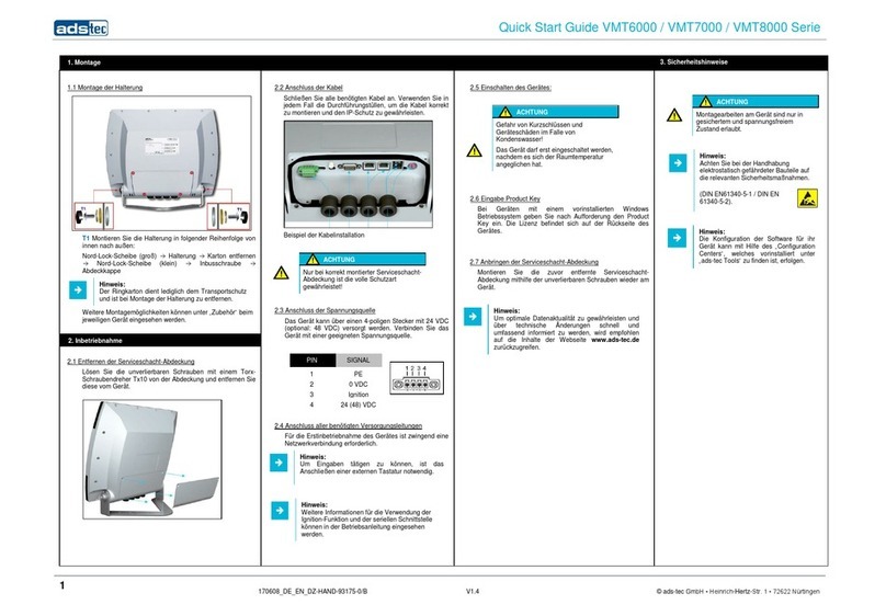
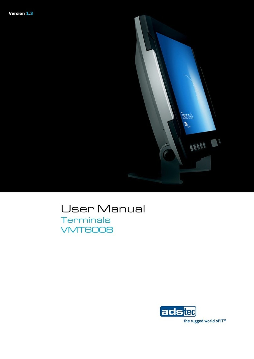
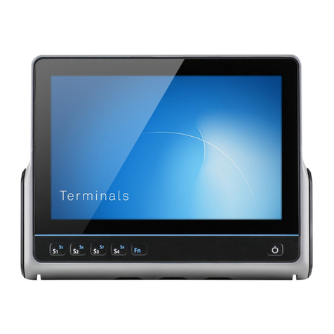
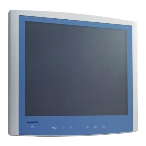
ADS-tec HDT8012 User manual

Updated 2018-02-12
Instruction manual
Terminal
HDT8012
Version 1.2
Translation of the
original manual

HDT8012 2
© ads-tec GmbH • Heinrich-Hertz-Str. 1 • 72622 Nürtingen
Table of Contents
1Notes 4
1.1 General remark 4
1.2 Limitation of liability 4
1.3 Manufacturer 4
1.4 Relevant device documentation 4
2Safety instructions 5
2.1 Structure of safety instructions 5
2.2 Graduation of risk level 5
2.3 Explanation of used symbols 5
2.4 Symbols 6
2.5 Data, figures and modifications 6
2.6 Trademarks 6
2.7 Copyright 6
2.8 Environmental conditions 7
2.9 Conformity 8
3Operating and safety instructions 9
3.1 Operating location 10
3.2 Damage due to improper use 10
3.3 Warranty / repairs 10
3.4 Intended use 10
3.5 Improper use 10
3.6 Treatment and disposal of lithium batteries 11
3.7 Safety instructions 12
4Product description 13
4.1 Features and interfaces 13
4.1.1 Front view 13
4.1.2 Rear view 14
4.1.3 Interfaces in the service slot 15
4.2 Power supply 16
4.3 Earthing (PE / FE) 17
4.4 Ignition function (IGN) 17
4.5 Autostart function (switch S1) 17
4.6 Serial interface X3 COM 18
4.7 LAN network connection 18
4.8USB connections 19

HDT8012 3
© ads-tec GmbH • Heinrich-Hertz-Str. 1 • 72622 Nürtingen
5Installation 20
5.1 External device dimensions 20
5.2 Installation via the VESA-75 interface 21
5.3 Other mounting options (optional) 22
6Commissioning 23
6.1 Scope of delivery 23
6.2 Check for operational readiness 23
6.3 Order of steps during commissioning 24
6.4 Operation 24
6.5 Decommissioning 24
7Operation 25
7.1 Touch screen 25
7.2 Status display with system LED 25
7.3 ON/OFF pushbutton 25
7.4 Speakers 26
8Drives 27
9Software & driver installation 28
10 Maintenance 29
10.1 Information on maintenance 29
10.2 Information on storing the batteries 29
11 Technical details 30
12 Service & support 31
12.1 ADS-TEC support 31
12.2 Company address 31

HDT8012 4
© ads-tec GmbH • Heinrich-Hertz-Str. 1 • 72622 Nürtingen
1 Notes
1.1 General remark
This instruction manual is intended to ensure safe and efficient handling of the device. It must be
accessible to all persons who are involved in installation and commissioning of the device and must be
read and understood before any work is started.
The instruction manual must be passed on to the device/system operator after commissioning has been
completed.
All of the safety instructions and handling instructions given in the manual must be obeyed in order to
ensure that work is carried out safely.
Figures used in this instruction manual are provided for basic understanding and may differ from the
actual design.
The original version of this instruction manual was written in German. All non-German versions of this
instruction manual are translations of the German instruction manual.
1.2 Limitation of liability
ads-tec GmbH shall not be liable for personal injury, property damage or damage caused to the device
as well as consequential damage that is/was the result of non-compliance with this instruction manual,
improper use of the device, repairs and other actions on the device by unqualified electricians and
electricians not certified by ads-tec, or that is/was the result of using unapproved replacement parts.
Failure to observe the maintenance intervals shall also result in exclusion from liability.
Furthermore, it is strictly forbidden to make any unauthorised alterations or technical modifications to
the device.
1.3 Manufacturer
The manufacturer of the product is ads-tec GmbH. The company is referred to in the following as ADS-
TEC.
1.4 Relevant device documentation
The following documents are decisive to device setup and operation:
Instruction manual (this documentation):
Contains information for installation, commissioning and operation of the device along with technical
data of the device hardware.
Website
You can download drivers, software, user manuals, leaflets and flyers about the product from our
website www.ads-tec.de.
Recommendation for use:
We would recommend to make use of our website contents www.ads-tec.de in
order to use current data and to be quickly and comprehensively informed of any
technical modification.

HDT8012 5
© ads-tec GmbH • Heinrich-Hertz-Str. 1 • 72622 Nürtingen
2 Safety instructions
2.1 Structure of safety instructions
The signal word classifies the hazard.
Reference to the type/consequences and source of the hazard is made underneath the signal word.
Information on how to avoid the hazard is indicated by an arrow ().
SIGNAL WORD
Type/consequences of hazard!
- Source of hazard
Measures to prevent hazard
2.2 Graduation of risk level
The signal word classifies the hazard.
Instructions for preventing the hazard are identified by an arrow ().
2.3 Explanation of used symbols
DANGER
Indicates an imminent danger. If not avoided,
death or severe injury will result.
WARNING
Indicates a possible danger. If not avoided, death
or severe injury could result.
CAUTION
Indicates a possible danger. If not avoided, light
or minor injuries could result.
ATTENTION
Indicates a possibly damaging situation. If not
avoided, the system or something in its
surroundings could be damaged.
Recommendation for use:
The symbol "Recommendation for use" indicates terms and/or conditions that
strictly need to be observed to ensure optimised and/or zero-defect operation.
Tips and suggestions for the efficient use of the device and software
optimisation are also provided.

HDT8012 6
© ads-tec GmbH • Heinrich-Hertz-Str. 1 • 72622 Nürtingen
2.4 Symbols
Symbol Meaning
Designation of batteries in accordance with § 13 of the
German Battery Act (BattG). Batteries may not be
disposed of with household waste, but must rather be
disposed of separately. Used batteries must be returned to
the point of sale or a disposal system.
Labelling of electrical and electronic devices in accordance
with § 7 of the German Electrical and Electronic
Equipment Act (ElektroG). Electrical and electronic
devices must not be disposed of with household waste,
but must rather be taken to a collection point for waste
electrical equipment. Such a collection point is generally
operated by public waste management authorities, i.e., by
municipalities.
Symbol for the protective earth connection
2.5 Data, figures and modifications
All data, text and figures were prepared to the best of our knowledge. They do not represent any
assurance for the properties themselves. Despite taking utmost care, no liability can be assumed for
accuracy, completeness and actuality of the information. Subject to changes.
2.6 Trademarks
It is noted that any software and/or hardware trademarks and any company brand names mentioned in
this documentation are all subject to the general trademark protection rights.
StoraXe® and Big-LinX® are registered trademarks of ADS-TEC.
All other used third-party trademarks are hereby acknowledged.
In the case of trademark infringement, ADS-TEC reserves the right to exercise all rights.
2.7 Copyright
This instruction manual is protected by copyright. For the authorised user, simple usage rights are
granted within the scope of the intent of the contract. Any modified use or exploitation of the provided
content, particularly duplication, modification or publishing in whatever form is permitted only with the
prior consent of ADS-TEC.
In the case of copyright infringement, ADS-TEC reserves the right to exercise all rights.

HDT8012 7
© ads-tec GmbH • Heinrich-Hertz-Str. 1 • 72622 Nürtingen
2.8 Environmental conditions
The device can be put into operation and used under the following conditions. Failure to observe any
one of these conditions will invalidate the warranty of the device. ADS-TEC cannot be held liable for any
damages arising from improper use and handling.
•Temperature
in operation* -20 ... 55°C**
for storage -40 ... 80°C
•Humidity
in operation 10 … 85% without condensate
for storage 10 … 85% without condensate
•Air quality: Pollution level 3 or lower according to EN 61131-2.
Vibration and shock resistance
In accordance with EN 60721-3-5 (Environmental conditions for devices for
terrestrial vehicles), the device satisfies the following classes:
•For mass storage type SSD (solid state drive): class 5M3
•For mass storage type HDD (hard disk drive): class 5M2
Testing was performed in accordance with the following test standards:
•EN 60068-2-6 – Vibration (sinusoidal)
(2 - 500 Hz, 40 m/s² peak value, 2 h each axis)
•EN 60068-2-27 – Shock resistance
(300 m/s², 11 ms, 3 shocks per axis)
•EN 60068-2-64 – Broadband noise
(3.6 g effective, 30 g peak value, 5 h long)
Testing was also performed in accordance with the following standard:
•MIL-STD 810F (January 1, 2000), annex C, figure 514.5C (US highway truck
transportation)
*) depending on mass storage device
**) The UL marking applies for operating temperatures up to max. 40°C.

HDT8012 8
© ads-tec GmbH • Heinrich-Hertz-Str. 1 • 72622 Nürtingen
2.9 Conformity
The manufacturer hereby declares that the product described in this instruction
manual complies with all relevant stipulations of the following European directives:
•2011/65/EC, RoHs Directive
•2014/30/EU, EMC Directive
•2014/35/EU, Low Voltage Directive
A corresponding EU conformity declaration is available for competent authorities at the
manufacturer and can be viewed upon request.
The EU conformity declaration can be requested at
http://www.ads-tec.de/support/support-anfrage.html and is available for download at
http://www.ads-tec.de/support/download/eg-konformitaetserklaerung.html.
Recommendation for use:
For full compliance with the EMC legislation, all components and cables
used for device connection must also be compliant with these requirements.
It is therefore necessary to employ BUS and LAN cables with shielded
connectors and these must be installed as per the instructions contained in
the instruction manual.

HDT8012 9
© ads-tec GmbH • Heinrich-Hertz-Str. 1 • 72622 Nürtingen
3 Operating and safety instructions
The device operates under electrical voltage and contains highly sensitive components. Intervention by
the user is required only for connecting the power supply lines. Should any further modifications be
required, it is necessary to consult either with the manufacturer directly or with service personnel
authorised by the manufacturer. The device must be de-energised during work. Appropriate measures
must be taken to prevent electrostatic discharges on components. If the device is opened up by an
unauthorised person, the user may be subject to hazards and the warranty is invalidated.
General information
•All users must read this manual and have access to it at all times.
•Installation, commissioning and operation may only be performed by qualified and
trained personnel.
•The safety notices and the manual itself must be observed by all persons who
work with this device.
•At the installation site the valid guidelines and regulations for accident prevention
must be observed.
•The manual contains the most important instructions on how to use this device in
a safe way.
•Appropriate storage, proper transport, installation and commissioning, as well as
careful operation are prerequisites for ensuring safe and proper operation of the
device.
•The device can be cleaned by using a soft cloth and a commercially available
glass cleaning agent (e.g. Sidolin) with low alcohol content.
ATTENTION
Hazard due to damage to device
Damage caused by connected peripherals or data loss
All cable lines (power supply, interface cables) should only be connected
while the device is switched off and de-energised.

HDT8012 10
© ads-tec GmbH • Heinrich-Hertz-Str. 1 • 72622 Nürtingen
3.1 Operating location
The device is designed for use in mobile agricultural and construction machinery. You have to take care
that the environmental conditions specified in the technical data are met. Use in non-specified
environments, i.e., on board ships, in explosive atmospheres or at extreme elevations, is prohibited.
The device must not be used to control vehicles. It must be ensured that the device is installed properly.
ATTENTION
Hazard due to condensation
Damage to electronic components caused by condensation resulting from temperature
fluctuations.
The device should only be switched on after it has acclimated to the ambient
temperature!
To avoid overheating in operation: The device must not be exposed to direct
radiation by sunlight or any other heat source.
3.2 Damage due to improper use
Should the control system have evident signs of damages caused, e.g., by improper operation or
storage conditions or due to improper use or handling, the device must be shut down immediately.
Ensure that it is secured against being started up accidentally.
3.3 Warranty / repairs
During the device warranty period, any repairs must only be performed by the manufacturer or by
service personnel that has been authorised by the manufacturer.
3.4 Intended use
The device is used for the visualisation, data acquisition and control of production and processing
procedures.
The device is only to be assembled, installed and operated within the permissible specifications. Use in
non-specified environments is prohibited.
3.5 Improper use
Operation other than or beyond that described for the device shall be deemed improper use.
The device is not allowed to be used to control vehicles or for applications for which further approvals
beyond the manufacturer's declaration are necessary, e.g. applications with explosion hazard, medical
technology, shipping industry.
The device must not be put into operation in the case of transport damage or nonconformity with the
specifications and, if necessary, must be taken out of operation in the case of changing conditions.
In the case of improper use, ADS-TEC shall not accept responsibility or liability for injury or damage that
is directly or indirectly attributable to the handling of the device.
Should the device have evident signs of damages caused, e.g., by improper operation or storage
conditions or due to improper use or handling, it must be shut down immediately. Ensure that it is
secured against being started up accidentally.

HDT8012 11
© ads-tec GmbH • Heinrich-Hertz-Str. 1 • 72622 Nürtingen
3.6 Treatment and disposal of lithium batteries
This device contains a lithium battery for supplying the system clock with power as long as the supply
voltage is not connected. The battery has a life cycle of 3-5 years depending on which load is applied.
ATTENTION
Hazard due to thermal loads
The more the battery is exposed to higher
temperatures, the faster it ages.
Avoid thermal loads
WARNING
Hazard due to explosion
Danger of explosion if using incorrect battery
types.
Use the battery type recommended by the
manufacturer.
Lithium batteries should not be exposed to fire, soldered, recharged, opened, short-circuited, reversed
or heated above 100 °C and they should be disposed of properly as well as protected against sunlight,
moisture and condensation.
The battery type to be used is:
oLithium battery 1/2AA 3V FDK Corp. CR14250SE
oADS-TEC part number: DZ-SONS-04100-0
The used lithium battery should be disposed of in accordance with local legal regulations.

HDT8012 12
© ads-tec GmbH • Heinrich-Hertz-Str. 1 • 72622 Nürtingen
3.7 Safety instructions
ATTENTION
Damages through electrostatic charging
Electrostatically sensitive charging can damage
components.
All installation and service work performed on
the device must be performed only under safe,
secure and de-energised conditions.
Recommendation for use:
Always adhere to the safety measures applicable when handling components at risk
of being damaged by electrostatic discharges.
The provisions of DIN EN 61340-5-1 / DIN EN 61340-5-2 apply

HDT8012 13
© ads-tec GmbH • Heinrich-Hertz-Str. 1 • 72622 Nürtingen
4 Product description
4.1 Features and interfaces
4.1.1 Front view
No. Description
1 Touch-sensitive screen (touch-screen)
→ see section 7.1
2 System LED
→ see section 7.2
1
2

HDT8012 14
© ads-tec GmbH • Heinrich-Hertz-Str. 1 • 72622 Nürtingen
4.1.2 Rear view
No. Description
3 Speakers → see section 7.4
4 Service slot for interfaces → see section 4.1.3
5 Interface VESA 75 → see section 5.2
6 Optional: ON/OFF push-button → see section 7.3
3
4
5
3
6

HDT8012 15
© ads-tec GmbH • Heinrich-Hertz-Str. 1 • 72622 Nürtingen
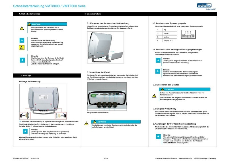
4.1.3 Interfaces in the service slot
Removing the service slot cover
Loosen the screws on the service slot cover by using a Torx Tx10 screw driver and remove the service
slot cover.
Interface overview:
No. Designation Description
1 X1:PE/0V/IGN/24V Power supply → see section 4.2
2 S1:AUTOSTART
OFF/ON Autostart → see section 4.5
3 X2:WLAN
S2:COM+5V:OFF/ON (X2:WLAN: not present)
S2: 5V on pin 9 of X3 → see section 4.6
4 X3:COM COM (RS232) → see section 4.6
5 X4:LAN1
X5:LAN2 LAN connections (RJ45)
→ see section 4.7
6 X6:USB1
X7:USB2
X8:USB3
USB connections (USB 2.0)
→ see section 4.8
7 - Cable entry grommets
8 PE Protective earth, → see section 4.3
8

HDT8012 16
© ads-tec GmbH • Heinrich-Hertz-Str. 1 • 72622 Nürtingen
4.2 Power supply
Power is supplied via a 4-pin plug (the figure shows the connector provided in the device).
Pin Signal
1 PE
2 0 VDC
3 IGN
4 24 VDC
Recommendation for use:
The power supply must be protected with a 4A fuse (slow-blow).
ATTENTION
Hazard due to damage to device
Damage caused by connected peripherals or data loss
All cable lines (power supply, interface cables) should only be connected while
the device is switched off and de-energised.
Pos: 18 /D atent ech nik/Inb etri ebnah me/R eihenf olge der Inbe trie bnah me/Rei henf olge der I nbetri ebna hme für VM T 60x x-Serie @ 1\mod_1222073159179_6.doc@ 4100@ : 19/Datentechnik/Inbetriebnahme/Betriebsbereitschaftprüfen/Betriebsbereitschaftprüfenfür OPC/CPC/ PLC/O TC/ITC /VMT-Ser ie(+ M onit or e) / IPC 5 10 0/5 500/ 24 00/ 110 0 @ 0\mod_1158905578361_6.doc@381 @
ATTENTION
Hazard due to overvoltage
The device can be destroyed by overvoltage.
Make certain that the permissible voltage values are maintained in
accordance with chapter Technical data.
Do not operate the device on vehicles that can exceed the permissible
system voltage.
Note on use in accordance with UL-Certification (Underwriter Laboratories):
The device is designed for an LPS supply (Limited Power Source/Class2).

HDT8012 17
© ads-tec GmbH • Heinrich-Hertz-Str. 1 • 72622 Nürtingen
4.3 Earthing (PE / FE)
The voltage supply (primary side) is electrically isolated from the internal power supply (secondary
side).
Note:
Proper function of the EMC filter is ensured only if the protective earth or the vehicle
earth is connected to pin 1 of the power supply connection.
Note:
When mounting on vehicles, a functional earth must be established.
An additional earthing connection via the earthing screw (see figure in section 4.1.3) is recommended
(wire cross section: min. 2.5mm²).
4.4 Ignition function (IGN)
The device can be started via pin 3 of the power supply. This function is known from the automotive
industry as the ignition function (ignition switch function). The device is continuously supplied with a 24
VDC power supply, but only if the additional signal is present at the release contact, e.g. as a result of
turning the ignition key of the vehicle, the computer is switched on.
The computer can also be automatically shut down in a time-controlled manner if voltage is no longer
present at the release contact.
Prefabricated supply cables are available from ADS-TEC for using this function.
4.5 Autostart function (switch S1)
The autostart function allows the automatic start-up of the device upon application of the supply voltage.
Note:
The Autostart switch in the service slot must be set to ON in order to use this
function, see section 4.1.3.

HDT8012 18
© ads-tec GmbH • Heinrich-Hertz-Str. 1 • 72622 Nürtingen
4.6 Serial interface X3 COM
Pos: 33 /D atent ec hni k/Sc hnit tstel l en/S eri ell e Sch nitt stel l e CO M RS 232 /Ser iel le Sc h nitts tell e C OM ( RS 232) f ür VMT 60 xx @ 1\mod_1246373571514_6.doc@ 5876@
The RS232 interface can be connected by using a shielded 9-pin Sub-D cable.
Note:
5 VDC can be connected to pin 9 of X3 (COM) to operate, e.g., a barcode
scanner. For this purpose, switch S2 COM +5V in the service slot must be
set to ON.
Interface IRQ Address
X3 COM 4 3F8h
Pin Signal
1 DCD
2 RxD
3 TxD
4 DTR
5 GND
6 DSR
7 RTS
8 CTS
9 RI or + 5 VDC
(max. 1 A)
Note:
This interface is not electrically isolated.
4.7 LAN network connection
Features:
10/100/1000Mbit/s, RJ45
2 x Intel I211 GbE network controllers
PXE-boot is supported (Preboot Execution Environment)

HDT8012 19
© ads-tec GmbH • Heinrich-Hertz-Str. 1 • 72622 Nürtingen
4.8 USB connections
These interfaces comply with the USB 2.0 standard requirements.
Pin Signal
1 VDC
2 D -
3 D +
4 GND
Note:
The USB interfaces have a current limit of 1 A per USB interface.
Pos: 30 /D atent ec hni k/Sc hnit tstel l en/P S2/K o mbi B uc hse f ür VM T 6 0x x @ 2\mod_1268840073235_6.doc@ 7482@

HDT8012 20
© ads-tec GmbH • Heinrich-Hertz-Str. 1 • 72622 Nürtingen
5 Installation
5.1 External device dimensions
Table of contents
Other ADS-tec Touch Terminal manuals
