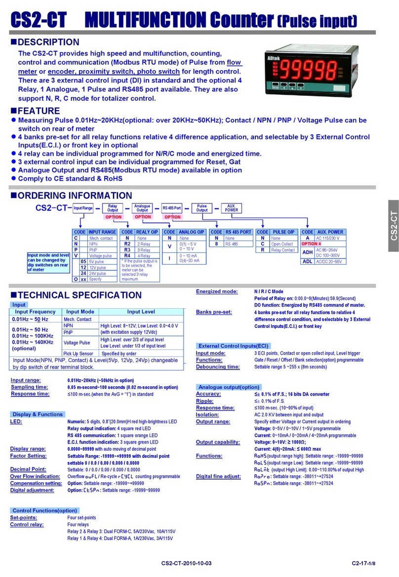
ADTEK CM1-CT User manual

MULTIFUNCTION COUNTER
Manual
CM1-CT
Rev 1.1
2017-02

CM1-CT
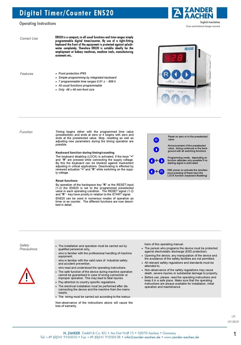
CM1-CT multifunction counter has 2 pulse inputs, applicable to proximity switch,
photoelectric sensor, encoder etc..
Counting function can be increase or decrease, positioning, batch count etc.., it’s
provided with display, Relay output and Modbus RTU communication port.
■Error Masage
MULTIFUNCTION COUNTER
1
■Connection Diagram
Terminal:
10A/300Vac,
M2.6, 1.3~2.0mm2
(16~12AWG)
Relay 2
COM ECI2
ECI1
ECI
Input
4 5 6 7 8 9 10
11 12 1413
Power Supply
D-S
12345
5
Signal Input
Count/Pulse
A +IN
+12Vd
c
23 24 25 26
15 16
COM
B +IN
AC115V
AC230V
2221
NC C NO NC C NO
Relay 1
Terminal:
10A/300Vac,
M2.6, 1.3~2.0mm2
(16~12AWG)
COM ECI2
ECI1
ECI
Input
4 5 6 7 8 9 10
11 12 1413
Power Supply
D-S
1 2 3 4 5
5
Signal Input
Count/Pulse
A +IN
+12Vd
c
23 24 25 26
15 16
COM
B +IN
AC115V
AC 230V
2221
A+ B-
RS485
port
AO
Output
Sensor Input
D-S
1
2
3
4
5
NPN
(12Vp)
PNP ON ON
M.C. ON ON
“ON” When switch in down
site
11 12 1413
A +IN
+12Vdc
B +IN
0V
A Out
+Vdc
COM
B Out
RS485 Communication Port Analog Output
21 22
Max.Distance: 1200M
Terminate Resistor
(at latest unit):
120~300ohm/0.25W
(typical: 150ohm)
A B
2423
Description Display
Positive-overflow (Signal over display range)
Negative-overflow (Signal under display range)
EEPROM occurs error
Note
Please check the input signal
Please check the input signal
ovfl
-ovfl
eep fail
Please send back to repaired
Reset
ENT/FN 6▲5 ▲4 ▲3 M
RL1 RL2
COM
Gate
E
RST
▲2 ▲1
Relay output
indicator
Operating key
Display Comm. indicator
Reset indicator
Display unit
Gate indicator
■Front Panel
Display: 0.8"(20.0mm) red high-brightness LED
: Relay 1 output indicator : Relay 2 output indicator
:RS485 communication indicator
ECI indicator: 2 green LED
:ECI 1 :ECI 2
Operating key (1) can be set to Reset function as ECI 1
Operating key (2) can be set to Gate function as ECI 2
RL1
RL2
COM
RST
GAT

2
■Operating Key
Operating Key : Up key (1~6, 5 and 6 are same a key) Enter/Function key
In parameter setting page, if didn’t press any key over 2 minutes, or press over 1 second,
then return to measuring page
Function
Enter/Function key
(1~6) Up key
(1) In function index page, press 1 second to back to previous page
(2) In function setting page, press 1 second to back to function index page
(3) In function setting page, press to next function page
(4) In parameter setting, press 1 second will abort setting and go back function page
(5) In parameter setting, press to enter value or confirm selection
(1)In function index page, press to function select
(2)In parameter setting, press to parameter select or numeric input
(press and hold can accelerate the numeric increase)
■Operating Flow Chart
Power ON
88888
cm1ct
ver1.5
1688.8
enter
Pcode
Pass code
MEASURING PAGE
Press 1 second
Press one second
NO
YES
Enter pass code into
Programming Level
Default :1000
0-0-1
19999 Counting value
(Normal)
0-1
ry1.sp Relay1 set-point
1~999999
(In mode setting range
can be -199999~999999)
10000 totl.l totl.h
0-2
ry2.sp Relay2 set-point
1~999999
(-199999~999999 same as Relay 1)
10000
0-3
cm1.ct Model name and
firmware version
dislay
ver1.5
User LevelUser Level
Programming Level
group
relay
RELAY GROUP
group
ao
AO GROUP
group
input
INPUT GROUP
group
init
INIT GROUP
A-1
B-1
C-1
D-1
iNtyp
up
Input Type select
Input A for counting up
Input B for Gate function
down
Input A for counting down
Input B for Gate function
abP-2
A/B Phase x2(double)
idv
Input A for counting up
Input B for counting down
cmd
Input A for counting signal
Input B for counting direction
ry1md
off
Relay 1 action
mode select
Disable
totLn
totLr
totLc
totLe
totLf
totLq
totLl
totLh
N mode
R mode
C mode
F mode
E mode
Q mode
L mode
H mode
aotyp
V0-10
Analog output
type and range
select
0~10 V
V0-5
V1-5
A0-10
A0-20
A4-20
0~5 V
1~5 V
0~10 mA
4~20 mA
0~20 mA
init
Input 7170 to
initialize meter
Next Page Next Page Next Page
Key
Go to E-1

1= Reset
2= Gate
3
A-2
B-2
C-2
E-1
pvtyp
Cnt
Present value
display select
Counting
Meter Length
ry1ot
Relay 1 action time
setting
0.00.0~9(M).59.9(S)
aols
Output Low scale
setting
0~+99999
0.00
group
RS485 Group
rs485
adres
Station address
1~247
1
C-3
aohs
Output High scale
setting
0~+99999
100.00
B-3
ry2md
A-3
ppr
Output pulse per
rotation setting
1~999999
E-2
baud
Baud rate
9600
C-4
aozro
Output zero fine
adjust setting
0~+29999
0.00
B-4
ry2ot
A-4
eunit
Length unit setting Relay 2 action time
setting
0.00.0~9(M).59.9(S)
1200 2400
4800 9600
19200
E-3
C-5
A-5
diant
Axis diameter setting
0.00001~9.99999
aospn
Output span fine
adjust setting
0~+29999
0.00
prity
Parity check
NstB2
nstb1
nstb2
odd
even
C-6
A-6
cntsf
Counting constant setting
0.00001~9.99999
*Display value =
Counting value x CNTSF
zsclr
Clear Zero/Span setting
none
none
aozro
aospn
both
C-7
A-7
ttldp
Decimal point of display
setting
aolmt
Output high limit setting
0.00~110.00%
110.00
00.0
0.00 0.000
A-8
o dfln
Process after
Overflow setting
A-9
ecikey
ECI function key setting
A-10
pcode
Pass code setting
0000~9999
Back to A-1
Back to B-1
Back to C-1
Back to E-1
off
Relay 2 action
mode select
Disable
totLn
totLr
totLc
totLe
totLf
totLq
totLl
totLh
N mode
R mode
C mode
F mode
E mode
Q mode
L mode
H mode
N,8,1
E,8,1
N,8,2
O,8,1
NONE
BOTH
AOZRO
AOSPN
ovFL!
rcycl Recycle counting
Display ’OVFL’
yes
no Disable
Enable
m
cm
yard
foot
M
FOOT
CM
YARD
*A-4 and A-5 are available when present
value display select is length mode

&'() *+,-./01
UP -A+ D OW N-F+ UP /D OW N-AF+
&2(
)#3
&2%O45%LM
P"Q&'
!"
999 99 9
#$% 2
#$% 1
0
OUT1
OUT2
!"
999 99 9
#$% 2
#$% 1
0
OUT1
OUT2
N
F
OUT 1
OUT 2
&2RSLM
P
RTK!"。
/&2KU,-
.&2R!"。
45%6789:;/
<=P"Q&'VR
!"。
/&2KU,
-K
OU T 2
!"
999 99 9
#$% 2
#$% 1
0
OUT1
OUT2
E
W*+X@K,
45%67Y!"P
Z[\],^_`*
+。
&2RSLMP
/&2KU,-
.&2VR!"。
SV
OU T1
OU T2
!"
999 99 9
#$% 2
#$% 1
0
OUT1
OUT2
!"
999 99 9
#$% 2
#$% 1
0
OUT1
OUT2
W*+X@K,
45%67Yab*+
,?@OUT2&2KU
,-.&2c4567
%!",_`*+。
OUT1&2RSLMP
OUT2/&2KU,-
.,&2VR!"。
SV
C
R
45%6789:;/
<=,?@ OU T 2
OUT 1
OUT 2
/&
2KU,-.67R
!"。
&2KU,-
.&2R!"。
/&2KU,-
.&2R!"。
!"
999 99 9
#$% 2
#$% 1
0
OUT1
OUT2
Q
45%6789:;/
<=。
OUT 1
OUT 2
&2KU,-
.&2R!"。
/&2RSLM
P"Q&'VR!"。
Operation after
count completion
Input mode
Up Down Up/Down-counting
Reset
Set 2
Set 1
Reset
Set 2
Set 1
Reset
Set 2
Set 1
Reset
Set 2
Set 1
Reset
Set 2
Set 1
Reset
Set 2
Set 1
As soon as the count
reaches SV, the
present value display
returns to the reset
start status.
Out 1 self-holding
output turn OFF after
the Out 2 one-shot
output time .
The Out 1 one-shot
output time is
independent of Out 2
The present value
display return to the
reset start status after
the one-shot output
time.
Out1 self-holding
output turns OFF after
the Out 2 one shot
output time
The Out 1 one-shot
output time is
independent of Out 2
■Relay Action Mode
Optional 2 relay output for N/C/R/E/F/Q/L/H 8 types of control mode.
Function details as below
The outputs and
present value display
are held until reset
The present value
display continues to
increase/decrease.
Out 1 self-holding
output turns OFF after
the Out 2 one-shot
output time.
The Out 1 one-shot
output time is
independent of Out 2.
The present value
display continues to
increase/decrease.
Out 1 self-holding
output turns OFF after
the Out 2 one-shot
output time
The Out 1 one-shot
output time is
independent of Out 2.
The present value
continues to increase/
decrease for the one-shot
output time, but returns to
the reset start status after
the one shot output time
has elapsed.
Out 1 self-holding output
turns OFF after the Out 2
one-shot output time.
The Out 1 one-shot output
time is independent of
Out 2.
4
Output
mode
setting

&'() *+,-./01
A B- dCe-AF+
&2(
)#3 !"
999999
#$% 2
#$% 1
0
OUT1
-99999
45%6789:;/<=,
?@ABCDEFBC%。
45%HIEJI#$%K,
&2LM。
45%NIEJI#$%K,
&2LM。
1
OUT1
2
OUT2
OUT2
!"
999999
#$% 2
#$% 1
0
OUT1
OUT2
-99999
45%6789:;/<=,
?@ABCDEFBC%。
45%NIEJI#$%K,
&2LM。
45%NIEJI#$%K,
&2LM。
1
OUT1
2
OUT2
Reset
Set 2
Set 1
Reset
Set 2
Set 1
Input
phase different up or down
Operation after
count completion
The display continues to
increase / decrease until the
overflow or underflow value is
reached.
Out 1 is held while the present
value is less than or equal to
set value 1.
Out 2 is held while the present
is greater than or equal to set
value 2.
The display continues to
increase / decrease until the
overflow or underflow value is
reached.
Out 1 is held while the present
value is greater than or equal
to set value 1.
Out 2 is held while the present
is greater than or equal to set
value 2.
■Modbus RTU Mode
1. Function 03H (Read Holding Registers )
Request Data Frame; EX: Read the data of display value (0000H starts from 1 word)
SLAVE
Address
FUNCTION Starting
Address Hi
Starting
Address Lo
NO. of Word
Hi
NO. of Word
Lo
CRC
Lo
CRC
Hi
01H 03H 00H 01H00H 00H 84H 0AH
Response Data Frame; EX: The response value is “0"
SLAVE
Address
FUNCTION Byte
count
Data
Hi
Data
Lo
CRC
Lo
CRC
Hi
01H 03H 02H 00H 00H B8H 44H
Request Data Frame; EX: Continue to request the data of 10 points
SLAVE
Address
FUNCTION Starting
Address Hi
Starting
Address Lo
NO. of Word
Hi
NO. of Word
Lo
CRC
Lo
CRC
Hi
01H 03H 00H 0AH00H 00H C5H CDH
Request Data Frame
SLAVE
Address
FUNCTION Byte
count
Data(1)
Hi
Data(1)
Lo
CRC
Lo
CRC
Hi
01H 03H 14H ....
00H 00H ............
.... ............ Data(10)
Hi
Data(10)
Lo
01H 00H
2. Writing Command by Function 06H (Preset Single Register)
.... ....
Request Data Frame
SLAVE
Address
FUNCTION Starting
Address Hi
Starting
Address Lo
Preset
DATA Hi
Preset
DATA Lo
CRC
Lo
CRC
Hi
01H 06H 00H 01H05H 00H 58H 0BH
Response Data Frame; EX: The response value is “0"
SLAVE
Address
FUNCTION Starting
Address Hi
Preset
DATA Hi
CRC
Lo
CRC
Hi
01H 06H 02H 00H 00H 58H 0BH
Starting
Address Lo
Preset
DATA Lo
01H
5
Output
mode
setting

■Communication Table
User Level
Name Address Range Explain Initial Write/Read Note
conut pv 0000h
0001h -199999~999999 Present Value R
Name Address Range Explain Initial R/W Note
count pv 0000h
0001h -199999~999999 Present Value R/W
Input Group
Name Address Range Explain Initial R/W Note
intyp 0002h 0~4 Input Type
0:UP 1:DOWN 2:AB.P-2 3:IDV 4:CMD R/W0
R/W0
R/W
1
R/W
0
pVtyp 0003h 0~1 PV Display Type
0:CNT 1:METER
ppr 0004h
0005h 1~999999 Output Pulse per Rotation
eunit 0006h 0~3 Unit of Length
0:M 1:CM 2:YARD 3:FOOT
R/W
1
diamt 0007h
0008h 0.0001~9.99999
R/W
1
cntsf 0009h
000Ah 0.0001~9.99999
R/W
0
ttldp
000Bh 0~3 Decimal Point of Display
0:0 1:0.1 2:0.00 3:0.000
R/W
0
oflmd
000Ch
0~1
Process after Overflow
0:OVFL 1:RCYCL
R/W
1
ecikey
000Dh
0~1
ECI Function Key Enable
0:YES 1:NO
R/W
1000
Pcode
000Eh
0000~9999
Pass Code
RS485 Group
Name Address Range Explain Initial R/W Note
adres 000Fh 1~247 Station address R/W1
R/W3
R/W
1
baud 0010h 0~5
Baud rate
0:1200 1:2400 2:4800 3:9600
4:19200 5:38400
prity 0011h 0~3 Parity check
0:N-8-1 1:N-8-2 2:O-8-1 3:E-8-1
INIT Group
Name Address Range Explain Initial R/W Note
init 0012h 0000~9999 Meter Initialization R/W
0 7170
6
Axis Diameter setting
Counting Constant setting
Other ADTEK Cash Counter manuals
