manuals.online logo
Brands
  1. Home
  2. •
  3. Brands
  4. •
  5. Baumer
  6. •
  7. Cash Counter
  8. •
  9. Baumer FLDK 110G1003/S14 User manual

Baumer FLDK 110G1003/S14 User manual

This manual suits for next models

10

Other Baumer Cash Counter manuals

Baumer IO-Link Master User manual

Baumer

Baumer IO-Link Master User manual

Baumer NE214 User manual

Baumer

Baumer NE214 User manual

Baumer NE216 User manual

Baumer

Baumer NE216 User manual

Baumer NE134 User manual

Baumer

Baumer NE134 User manual

Baumer NE212 User manual

Baumer

Baumer NE212 User manual

Baumer NE210 User manual

Baumer

Baumer NE210 User manual

Baumer NE215 User manual

Baumer

Baumer NE215 User manual

Baumer ISI Series User manual

Baumer

Baumer ISI Series User manual

Baumer NE230 User manual

Baumer

Baumer NE230 User manual

Baumer ME102 User manual

Baumer

Baumer ME102 User manual

Baumer Scatec-10 User manual

Baumer

Baumer Scatec-10 User manual

Popular Cash Counter manuals by other brands

Measurement Computing USB-4301 user guide

Measurement Computing

Measurement Computing USB-4301 user guide

Polar Electro U Series instruction manual

Polar Electro

Polar Electro U Series instruction manual

Tranax Mini-Bank 1500 Operator's manual

Tranax

Tranax Mini-Bank 1500 Operator's manual

Omron H7CL Series manual

Omron

Omron H7CL Series manual

Olympia NC-350A Series user guide

Olympia

Olympia NC-350A Series user guide

XIA UltraLo-1800 user manual

XIA

XIA UltraLo-1800 user manual

Cashmaster Sigma 105 quick start guide

Cashmaster

Cashmaster Sigma 105 quick start guide

Agilent Technologies 53151A operating guide

Agilent Technologies

Agilent Technologies 53151A operating guide

Cashmaster Sigma 105 user manual

Cashmaster

Cashmaster Sigma 105 user manual

HYOSUNG MX-4000W Operator's manual

HYOSUNG

HYOSUNG MX-4000W Operator's manual

Cashmaster Sigma 105 user manual

Cashmaster

Cashmaster Sigma 105 user manual

HP 53150A Series Programming guide

HP

HP 53150A Series Programming guide

HYOSUNG 1800CE owner's manual

HYOSUNG

HYOSUNG 1800CE owner's manual

FAAC XTR B manual

FAAC

FAAC XTR B manual

MZ electronic EV-040 Instructions for use

MZ electronic

MZ electronic EV-040 Instructions for use

Evco EV7001 manual

Evco

Evco EV7001 manual

Delfield Shelleysteel SCFM-50 Specifications

Delfield

Delfield Shelleysteel SCFM-50 Specifications

Record FlowControl user manual

Record

Record FlowControl user manual

manuals.online logo
manuals.online logoBrands
  • About & Mission
  • Contact us
  • Privacy Policy
  • Terms and Conditions

Copyright 2025 Manuals.Online. All Rights Reserved.

SCATEC-2
Laser - Exemplarzähler
Laser Copy Counter
FLDK 110G1003/S14
FLDK 110G1003/S42
FLDK 110C1003/S42
FLDK 110G1005/S14
FLDK 110G1005/S42
FLDK 110C1005/S42
FLDK 110G1006/S14
FLDK 110C1006/S42
FLDK 110C1303/S42
FLDK 110G1303/S14
FLDK 110x10/xxxxxx
User manual
Manual SCATEC-2 2Baumer Electric AG
Version 2021-09 www.baumer.com Frauenfeld, Switzerland
General notes
Rules for proper
usage
This product represents a precision measuring device which has been
designed for the detection of objects and parts. It generates and provides
measured values issued as electrical signals for following systems.
Unless this product has not been specifically marked it may not be used in
hazardous areas.
Set-up
Installation, mounting and adjustment of this product may only be executed
by skilled employees.
Installation
Only mounting devices and accessories specifically provided for this product
may be used for installation.
Unused outputs may not be connected. Unused strands of hard-wired
sensors must be isolated. Do not exceed the maximum permissible bending
radius of the cable. Before connecting the product electrically the system
must be powered down.
Where screened cables are mandatory, they have to be used in order to
assure EMI protection. When assembling connectors and screened cables
at customer site the screen of the cable must be linked to the connector
housing via a large contact area.
Manual SCATEC-2 3Baumer Electric AG
Version 2021-09 www.baumer.com Frauenfeld, Switzerland
0Table of Contents
1. Safety information and Certifications
2. Introduction
3. Principle of operation
4. Part identification
5. Terms and definitions
6. Signal sequence
7. Installation
8. Adjustments
9. Instructions for use
10. Specifications
11. Accessories
12. Maintenance
13. Troubleshooting
14. Varying data for customized FLDK 110x10/xxxxxx
FLDK 110x10/xxxxxx
Check section 14 for data
and information varying
from the standard manual !
Manual SCATEC-2 4Baumer Electric AG
Version 2021-09 www.baumer.com Frauenfeld, Switzerland
1Safety information and Certifications
The laser diode installed inthe SCATEC-2 emits visible redlight. This
laser belongs to the Class 2 laser standard specified by the IEC
60825-1 / 2014.
Avoid looking directly into the beam for long periods. Brief
irradiation of the eye (0.25 sec) that can occur during an
accidental glance is not regarded to be dangerous.
However, the laser should not be aimed deliberately at people. The
laser beam should also be blocked at the end of its intended path.
Disconnect the sensor if front windows or optical elements are
loose or broken!
Scatec-2 complies with the
following safety standards:
Complies with 21 CFR 1040.10 and 1040.11 except for conformance
with IEC 60825-1 Ed. 3., as described in Laser Notice No. 56, dated
May 8, 2019.
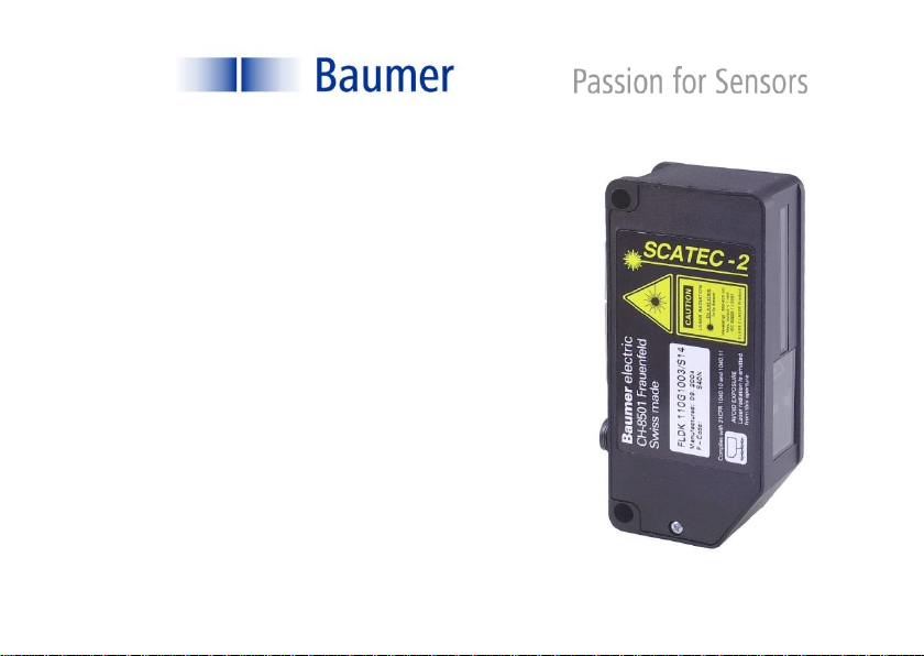
Manual SCATEC-2 5Baumer Electric AG
Version 2021-09 www.baumer.com Frauenfeld, Switzerland
2Introduction
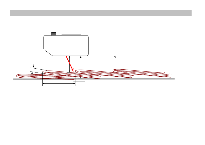
SCATEC-2 has the same key feature as all the other sensors from the SCATEC family: The capability of
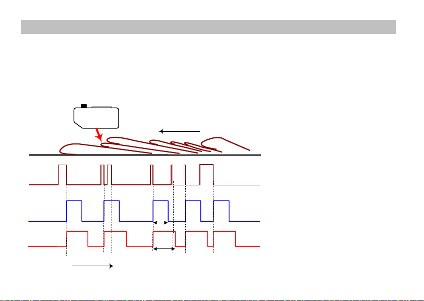
non-contact detection of object edges. SCATEC is the sensor of choice when it comes to detect flat
objects conveyed in an overlapping stream or individually. The sensors in the SCATEC family were
developed and highly optimized particularly with regard to the specific demands of non-contact counting
of overlapping paper sheets and newspapers. Therefore the printing industry will be the ideal area of
application for the SCATEC.
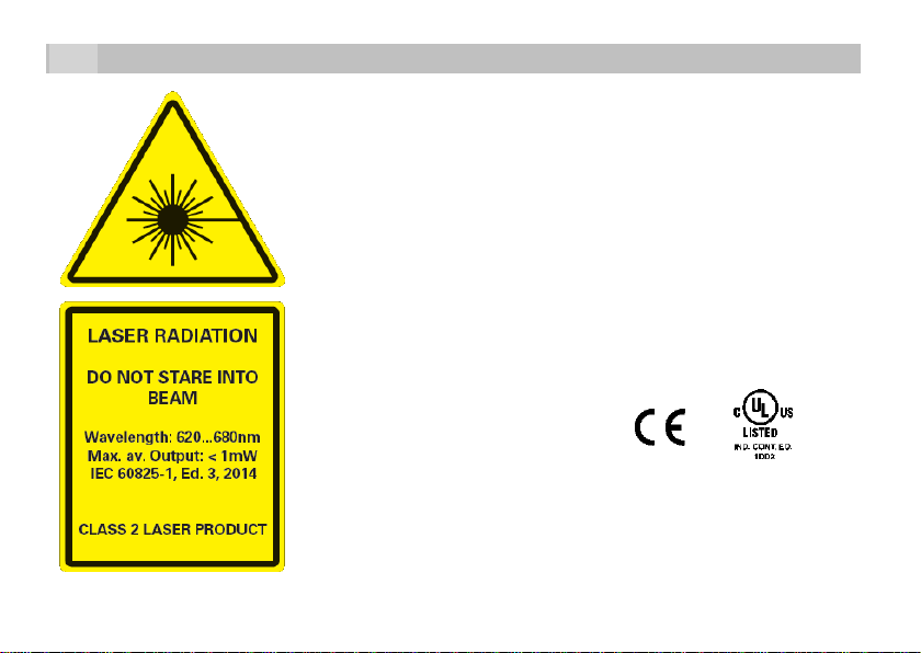
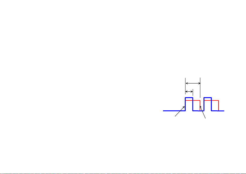
Generally speaking a SCATEC sensor reacts to an edge facing the sensor’s laser beam. If the laser beam
strikes such an edge, SCATEC responds with an electrical output pulse of fixed duration. However, built-
in software allows the sensor among other things to suppress the reaction to certain edges which were
identified by the sensor as “false edges”. Therefore, SCATEC-2 makes it possible to count newspapers
to the highest degree of accuracy even at high conveyor speed.
Within the SCATEC family, the SCATEC-2 is characterized by the following properties:
(For details see specifications of the individual Scatec-2 types.)
counts edges from a thickness of 0.2 mm and greater
optimum working distance: 40 mm or 100 mm
intelligent false pulse suppression
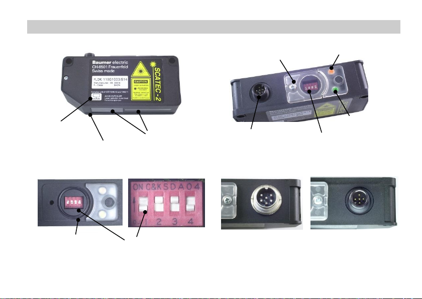
parameter setting by means of DIP-switches
counting rate up to 600,000 copies per hour
with interface for remote control and data analysis
Manual SCATEC-2 6Baumer Electric AG
Version 2021-09 www.baumer.com Frauenfeld, Switzerland
3Principle of operation
Described simply, the SCATEC-2 consists of a laser light source and two photodetectors. The beam is
aimed diagonally at the objects to be detected. Photodetector Ris located close to the laser light source
and photodetector Va little further away. The sensor measures the ratio between signal v(light scattered
forward) and signal r(light scattered backward).
The ratio v/r differs widely depending whether the beam strikes on a flat surface or on an edge. When an
edge moves into the laser beam, the direct line of sight from detector Vto the point of contact of the laser
is obstructed, which reduces signal v, and the edge also
increases the backward scattering, causing signal rto
increase. Both effects cause ratio v/r to become substantially
smaller than with a flat surface. If ratio v/r falls below a
specific level, the sensor interprets this as an edge.
This principle of operation clearly demonstrates that:
The orientation of the object to the beam is significant.
An edge facing towards the beam creates a small ratio v/r, in
contrast to an edge facing away from the beam.
Edge detection is independent of the color, as only the
ratio of the light intensities and not the absolute value is used
for detection.
Manual SCATEC-2 7Baumer Electric AG
Version 2021-09 www.baumer.com Frauenfeld, Switzerland
4Part identification
Edge-LED (yellow)
Sensor plug
Front window
Alignment aid
Lower edge of sensor
DIP-switches
DIP-switch cover
with screw
DIP-switches
O-ring
Power-LED (green)
Connector : .../S42 .../S14
Manual SCATEC-2 8Baumer Electric AG
Version 2021-09 www.baumer.com Frauenfeld, Switzerland
5Terms and definitions
For reference, the terms defined in this section are used throughout the manual.
Conveying plane
kFront edge Tail edge
d
Beam blocker
a
h
Running
direction
Mounting height: hDistance between the lower edge of the sensor and the conveying
plane.
Working plane The edge lies on the working plane. With thick overlapping copies, the
working plane is slightly higher than the top of the conveying plane on
which the copies are transported. Distance dis measured vertically to
the lower edge of the sensor.
Working distance: dDistance between the lower edge of the sensor and the working plane.
Manual SCATEC-2 9Baumer Electric AG
Version 2021-09 www.baumer.com Frauenfeld, Switzerland
Overlap: aDistance between two successive edges, measured along the
conveying plane. (Also referred to as the object spacing.)
Edge thickness: kThickness of the copy at the point where the edge is to be detected.
Front edge The edge of an object facing the laser beam. Front edges are detected
by the sensor.
Tail edge The edge of an object facing away from the laser beam. Tail edges are
not detected by the sensor unless they are pointing upwards.
Running direction The preferred running direction (front edges leading) is indicated. The
opposite direction is also permitted by the SCATEC-2.
Dead time tThe sensor responds to an edge with an output pulse with length p. The
dead time begins when the pulse
is issued. The sensor can only
issue the next pulse after both the
dead time tand the output pulse p
have expired. This means: an
edge detected by the beam while
still either the dead time tor the the
output pulse pis on does not
initiate an output pulse.
False pulse Output pulse generated by an
edge which should not be counted.
Output pulse
Dead time
p
t
Manual SCATEC-2 10 Baumer Electric AG
Version 2021-09 www.baumer.com Frauenfeld, Switzerland
6Signal sequence
The yellow edge indicator LED lights as long as an edge is located in the beam. The output pulse is issued
at the end of the edge. The dead time begins when the output pulse is issued. During the dead time and
when issuing the pulse, the SCATEC-2 is inactive, i.e. an edge ending during the dead time or the pulse
issue of the previous edge will not initiate an output pulse. Therefore, the next output pulse can only be
issued after the dead time has expired and the output pulse has been issued.
yellow edge-LED
output pulse (pulse length:p)
dead time (period:t)
Running direction
on
off
high
low
on
off
time
t
p